1 page HONDA CIVIC 1996 6.G Workshop Manual
[x] Cancel search | Manufacturer: HONDA, Model Year: 1996, Model line: CIVIC, Model: HONDA CIVIC 1996 6.GPages: 2189, PDF Size: 69.39 MB
Page 1025 of 2189
l.
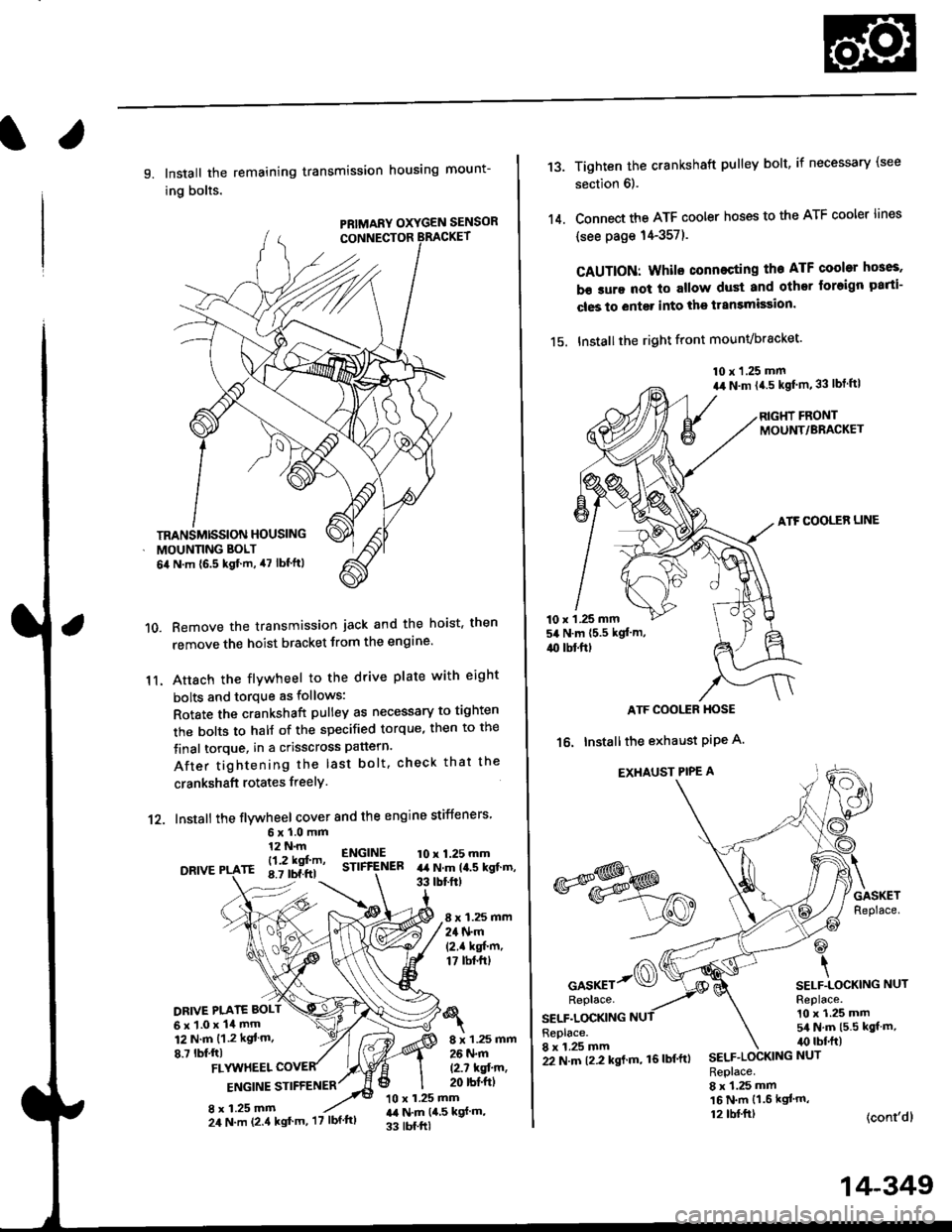
9. Install the remaining transmission housing mount-
ing bolts.
PRIMARY OXYGEN SENSOR
Remove the transmission jack and the hoist. then
remove the hoist bracket from the engine'
Attach the flvwheel to the drive plate with eight
bolts and torque as follows:
Rotate the crankshaft pulley as necessary to tighten
rhe bolts to half of the specified torque, then to the
final torque, in a crisscross pattern.
After tightening the last bolt. check that the
crankshaft rotates freelY.
10.
11.
12. Install the flywheel cover and the engine stiffeners
DRIVE
6xl.0mm12 N.m
- l12 kgf'm'rE 8.7 tbf.ftl
ENGINESTIFfENEB10 x 1.25 mmart N.m la.s kgt.m,33 tbtftt
8 x 1.25 mm24 N.m(2.1 kgf'm,17 tbt.ftt
DRIVE PI.ATE BOLT
6x1.0x14mm12 N.m {1.2 kgt m.
8.7 lbf,ftl8 x 1.25 mm26 N.m
12.7 kqfin,20 rbt'ftlFLYUTHEEL
ENGINE STIFFENER
8 x 1.25 mm10 x 1.25 mmr,a N.m {4,5 kgf m,
33 tbf.ftl
TRANSMISSION HOUSING
MOUNNNG BOLT
6il N.m {6.5 kgf.m, 47 lbf'ftl
24 N.m (2.4 kgt'm, '17 lbf'ftl
22 N.m t2.2 kgl m, 16lbf'ftl
14-349
13.
14.
Tighten the crankshaft pulley bolt, if necessary (see
section 6).
Connect the ATF cooler hoses to the ATF cooler lines
(see page 14-357).
CAUTION: Whilo connecting the ATF cooltr hGes,
b€ sure not lo allow dust and other loreign parti-
cles to entg. into the transmission.
15. Installthe right front mounvbracket'
10 x 1.25 mm
a,r N.m {4.5 kgf'm,33 lbt ftl
RIGHT FRONTMOUNT/BRACKET
ATF COOLER LINE
10 x 1 .25 mm54 N.m {5.5 kgt'm,
4{) tbl.ftt
ATF COOI,TR HOSE
16. Installthe exhaust PiPe A.
EXHAUST PIPE A
GASKETReplace.
@
\SELF.LOCKING NUTReplace.10 x 1.25 mm5/a N.m {5.5 kgt m,irc lbf.ft)
(cont'dl
*s$o
oor*rr-@Replace.
SELF.LOCKINGReplace.8 x 1.25 mmSELF.LOCKING NUT
Replace.8 x 1.25 mm16 N.m {1.6 kgl'm,12 tbl.ftt
Page 1027 of 2189

22. Install the shift cable end on the control lever, and
install the shift cable on the shift cable bracket'
CAUTION: Take care not to bend the shift cable'
23. lnstall the clip in the direction shown.
LOCKNUT
SHIFI CABLE 29 N m {3.0 kg{ m, 22lblftl
SHIFT CABLEERACKET
WASHERIPLASTIC)
CONTROL LEVER
24, Connect the solenoid harness connector. the drive
pulley speed sensor connector. and the ground
cable terminals.
6x1.0mm12 N.m {1.2 kgf.m.8,7 rbtft)
GROUND CABLETERMINAL 6x1.0mm
GROUNDTERMINAL
12 N.m {1.2 kgf'm,8.7lbtfrl
DRIVE PULLEYSPEED SENSORCONNECTOR
SOLENOID HARNESS
CONNECTOR
25. Connect the starter motor cable on the starter motor.
and install the cable holder.
NOTE: When installing the staner motor cable. make
sure that the crimped side of the ring terminal is
facing out (see section 23).
STARTEB
BMOUNTING NUT
9 N.m (0.9 kgf m,7 lbf ft)
26. Install all removed connectors and clamps'
27. Install the distributor.
28. Install the intake air duct and air cleaner housing
29.
assemDly.
Refill the transmission with the recommended
Genuine Honda CVT Fluid (see page 14-2991
CAUTION: While filling the CvT Fluid, bs surs not io
allow dust and other fotoign particles to entor into
the transmission.
Connect the battery positive (+) terminal first, then
the negative (-l terminal to the battery'
Check the ignition timing (see section 23).
Start the engine. Set the parking brake, and shift the
transmission through all gears three times Check
shift cable adjustment (see page 14-355).
Check the front wheel alignment (see section 18)
Let the engine reach operating temperature (the
radiator fan comes on) with the transmission in lXl
or E position, then turn it off and check fluid level'
Perform the start clutch calibration procedure on
page 14-293.
Road test as described on pages 14-296 and 14-297
30.
31.
34.
36.
STARTER MOTOR
14-351
Page 1029 of 2189
![HONDA CIVIC 1996 6.G Workshop Manual l.
17.Make sure the transmission is in the E] position.
Fill the transmission with cvT Fluid, and run the
engine for 30 seconds or until approximately 0 95 {
(1.0 US qt.,0.8 lmp qt.) is discharged.
Re HONDA CIVIC 1996 6.G Workshop Manual l.
17.Make sure the transmission is in the E] position.
Fill the transmission with cvT Fluid, and run the
engine for 30 seconds or until approximately 0 95 {
(1.0 US qt.,0.8 lmp qt.) is discharged.
Re](/img/13/6068/w960_6068-1028.png)
l.
17.Make sure the transmission is in the E] position.
Fill the transmission with cvT Fluid, and run the
engine for 30 seconds or until approximately 0 95 {
(1.0 US qt.,0.8 lmp qt.) is discharged.
Remove the drain hose, and reconnect the cooler
return hose to the transmission (see page 14-355)
Refill the transmission with CVT Fluid to the proper
level (see page 14-299).
18.
'19.
.l ,
TOOL MAINTENANCE
1. Empty and rinse after each use. Fill the can with water
and pressurize the can. Flush the discharge line to
ensure that the unit is clean.
2, lf discharge liquid does not foam, the orifice may be
blocked.
3. To clean, disconnect the plumbing from the tank at
the large couPling nut.
FILTER
\
\- 0--D
i
I
O.RING
Remove the in-line tilter from the discharge side and
clean if necessary'
The fluid orifice is located behind the filter. Clean it
with the pick stored in the bottom of the tank han-
dle. or blow it clean with air. Securely reassemble
all parts.
COUPLINGNUT
II
-@q
\ORIFICE
FILLER CAP
14-353
Page 1030 of 2189
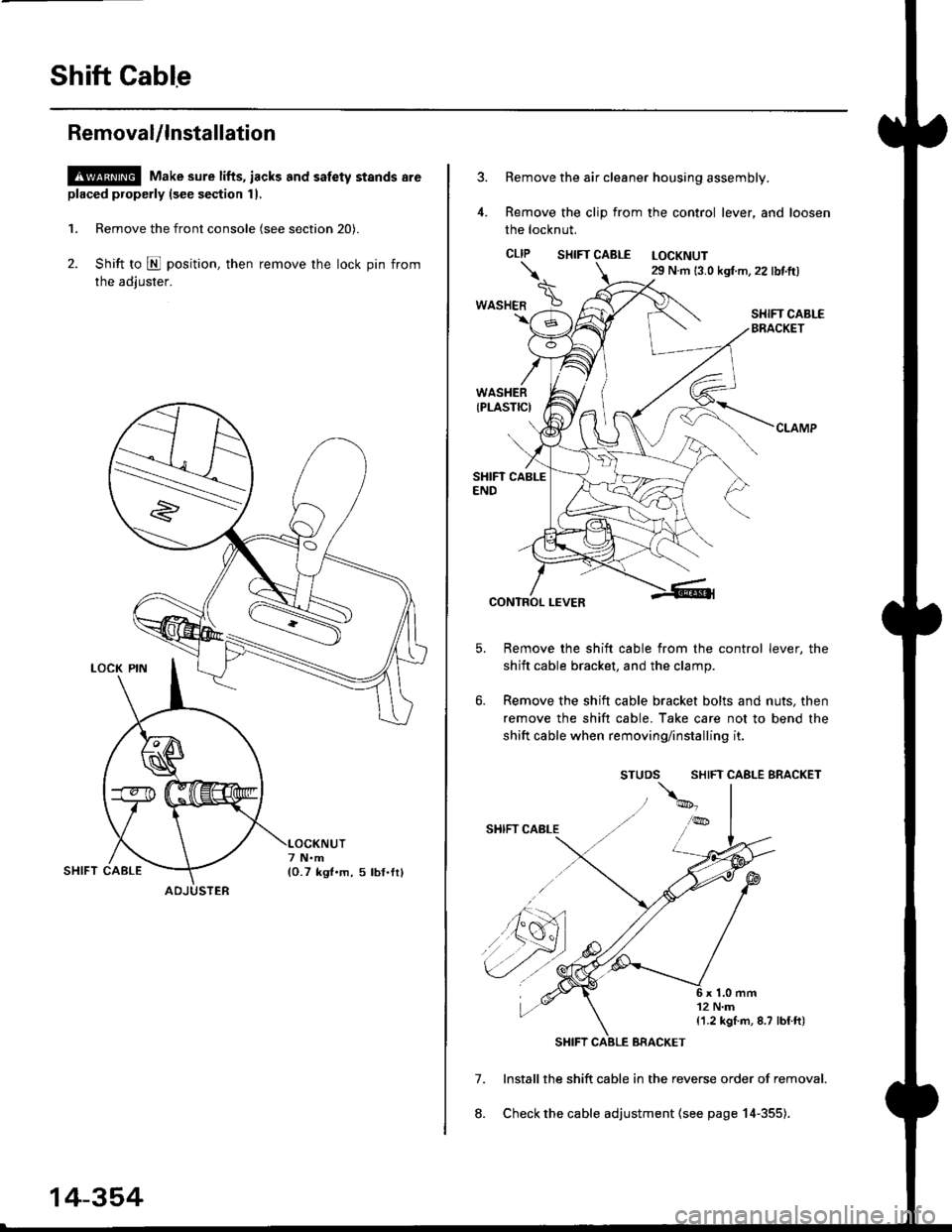
Shift Cable
RemovaUlnstallation
@ Make sure lifts, iacks and safety stands are
placed properly (see seqtion 11,
1. Remove the front console (see section 20).
2. Shift to E position, then remove the lock pin from
the adiuster.
ADJUSTER
14-354
Remove the air cleaner housing assembly.
Remove the clip from the control lever, and loosen
the locknut.
CLIP SHTFT CABLE LOCKNUT29 N.m 13.0 kgf m,22 lbf.ft)
SHIFT CABI-EBRACKET
7.
8.
CONTROL LEVER
Remove the shift cable from the control lever, the
shift cable bracket, and the clamp.
Remove the shift cable bracket bolts and nuts, then
remove the shift cable. Take care not to bend the
shift cable when removing/installing it.
SHIFT CABLE BRACKET
lnstall the shift cable in the reverse order of removal.
Check the cable adjustment (see page 14-355).
\.
*o"ra" \
{1.2 kgI m, 8.7 lblft)
Page 1031 of 2189
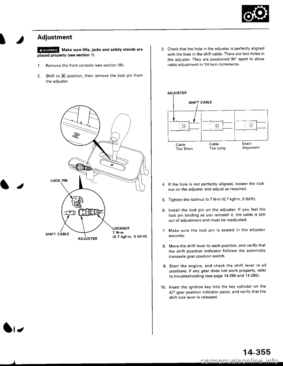
t
Adjustment
!@ Make sure lifts, jacks and safety stands are
placed properly (see section 1).
l. Remove the front console (see section 20).
2. Shift to I posirion, then remove the lock pin from
the adjuster.
SHIFT CAELE
l,
,l
{0.7 kgf.m, 5lbf'ltl
3. Check that the hole in the adiuster is perfectly aligned
with the hole in the shift cable. There are two holes in
the adjuster. They are positioned 90" apart to allow
cable adjustment in 1/4 turn increments.
lf the hole is not perfectly aligned, loosen the lock-
nut on the adjuster and adjust as required.
Tighten rhe locknut to 7 N.m (0.7 kgim,5 lbf'ft).
Install the lock pin on the adjuster' lf you feel the
lock pin binding as you reinstall it. the cable is still
out of adjustment and must be readjusted
Make sure the lock pin is seated in the adiuster
securery.
lMove the shift lever to each position, and verify that
the shift position indicator follows the automatlc
transaxle gear position switch.
Start the engine, and check the shift lever in all
positions. lf any gear does not work properly, refer
to troubleshooting (see page 14-294 and 14-295).
Insert the ignition key into the key cylinder on the
Aff gear position indicator panel, and verify that the
shift lock lever is released.
7.
10.
14-355
Page 1053 of 2189
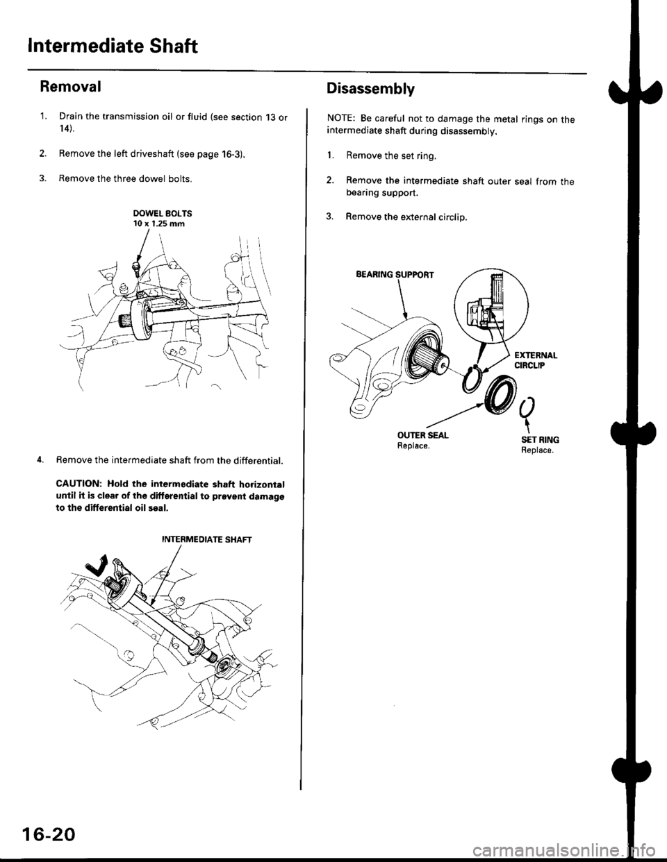
Intermediate Shaft
Removal
Drain the transmission oil or fluid {see section 13 or
r 4).
Remove the left driveshaft (see page 16-3).
Remove the three dowel bolts.
OOWEL BOLTS'10 x 1.25 mm
Remove the intermediate shaft from the differential.
CAUTION: Hold the intermsdiate shaft horizontal
until it is clear of lhe dilterential to prevent damage
to the differential oil seal.
'1.
2.
3.
INTERMEDIATE SHAFT
16-20
Disassembly
NOTE: Be careful not to damage the metal rings on theintermediate shaft during disassembly.
1. Remove the set ring.
2. Remove the intermediate shaft outer seal from theDeaflng suppon.
3. Remove the external circlip,
Page 1059 of 2189
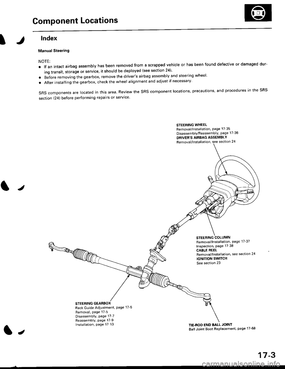
Component Locations
tlndex
Manual Steering
NOTE:
. lf an intact airbag assembly has been removed from a scrapped vehicle or has been found defective or damaged dur-
ing transit. storage or service, it should be deployed (see section 24)'
o Before removing the gearbox, remove the driver's airbag assembly and steering wheel
. After insta lling the gearbox, check the wheel alignmentand adjust if necessary
SRS components are located in this area. Review the SRS component locations, precautions, and procedures in the SRS
section 124) before performing repairs or service'
STEERING WHEELRemoval/lnstallation, Page 17'35
Disassembly/FeassemblY, page 17-36
DRIVER'S AIRBAG ASSEMBLY
Removal/lnstallation, see section 24
STEERING COLUMNRemoval/lnstallation, Page 17-37
Inspection, page 17'38
CABLE REELRemoval/lnstallation, see section 24
IGNTTION SWITCH
See section 23
STEERING GEARBOXRack Guide Adiustment, Page 17-5
Removai, page 17'5Disassembly, Page 17_7Reassembly, page 17_9Installation, page 17 13TIE.ROD END BALL JOINT
Ball Joint Boot Replacement, page 17-68
J
t,
17-3
Page 1060 of 2189
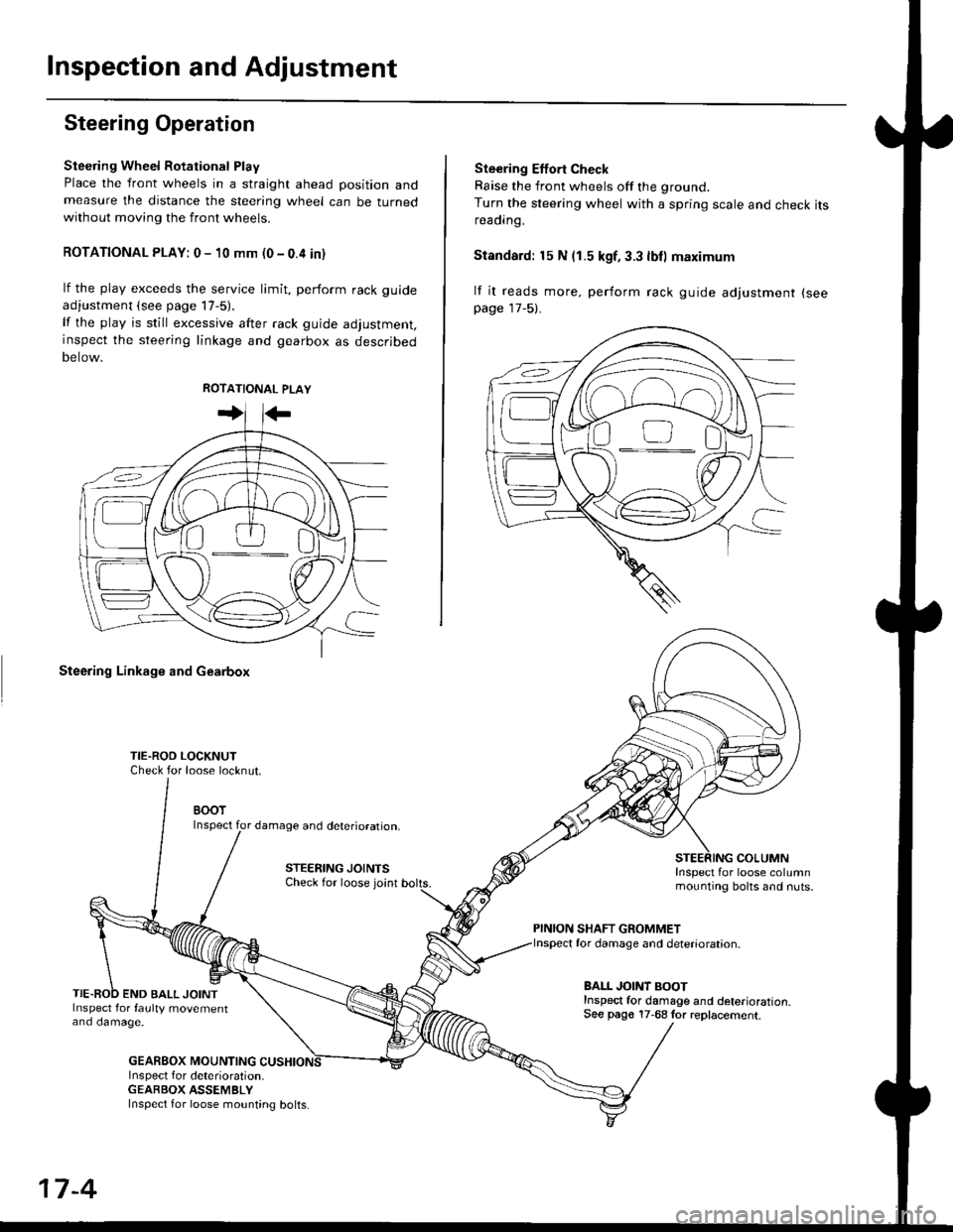
Inspection and Adjustment
Steering Operation
Steering Wheel Rotational Play
Place the front wheels in a straight ahead position andmeasure the distance the steering wheel can be turnedwithout moving the front wheels.
ROTATIONAL PLAY: 0 - 10 mm (0 - 0.4 in)
lf the play exceeds the service limit, perform rack guide
adjustment (see page lT-5).
lf the play is still excessive after rack guide adjustment,inspect the steering linkage and gearbox as descrjbed
Detow.
Steering Linkage and Gearbox
TIE.ROO LOCKNUTCheck for loose locknut.
BOOTInspect for damage and deterioration.
STEERING JOINTSCheck for loose joint
END BALL JOINTInspect for faulty movementano oamage.
GEABBOX MOUNTINGInspect f or deterioration.GEABBOX ASSEMBLY
Ste€ring Effort Check
Raise the front wheels off the ground.
Turn the steering wheel with a spring scale and check itsreaorng,
Standard: 15 N (1.5 kgf, 3.3 lbll maximum
lf it reads more. perform rack guide adjustment (see
page 17-5).
COLUMNInspect for loose columnmounting bolts and nuts.
PINION SHAFT GROMMETfor damage and deterioration.
BALL JOINT BOOTInspect for damage and deterioration.See pago 17-68 tor replacement.
ao-\---------U
17-4
Inspect for loose mounting bolts.
Page 1061 of 2189
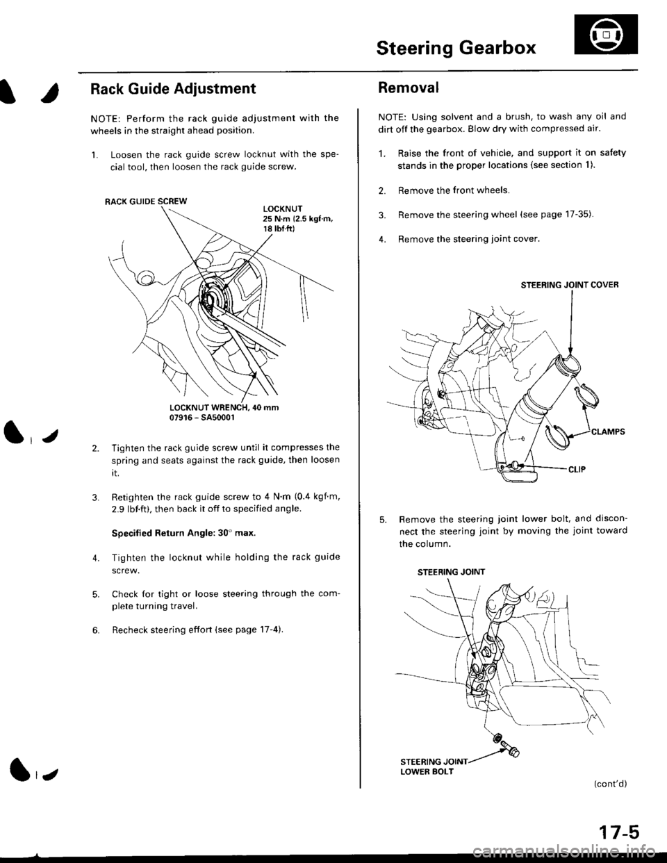
Steering Gearbox
l.r
Rack Guide Adjustment
NOTE: Perform the rack guide adjustment with the
wheels in the straight ahead position.
1. Loosen the rack guide screw locknut with the spe-
cial tool, then loosen the rack guide screw.
LOCKNUT WRENCH, 40 mm07916 - SA5000r
Tighten the rack guide screw until it compresses the
spring and seats against the rack guide, then loosen
rt.
Retighten the rack guide screw to 4 N'm (0.4 kgf m,
2.9 lbf.ft), then back it off to specified angle.
Specilied Return Angle: 30' max.
Tighten the locknut while holding the rack guide
Check for tight or loose steering through the com-
plete turning travel.
Recheck steering effort (see page 17-4).
4.
RACK GUIDE SCREW
l,z
Removal
NOTE: Using solvent and a brush, to wash any oil and
dirt off the gearbox. Blow dry with compressed air.
1. Raise the front of vehicle, and support it on satety
stands in the proper locations (see section I ).
2. Remove the front wheels.
3. Remove the steering wheel (see page 17-35).
4. Remove the steering loint cover
Remove the steering joint lower bolt, and discon-
nect the steering joint by moving the joint toward
the column.
(cont'd)
17-5
STEERING JOINT COVER
LOWER BOLT
STEERING JOINT
Page 1066 of 2189
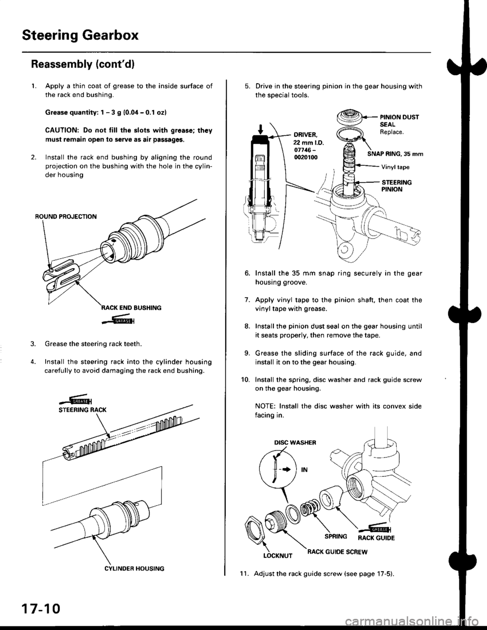
Steering Gearbox
Reassembly (cont'dl
LApply a thin coat of grease to the inside surface of
the rack end bushing.
Grease quantity: 1 - 3 S 10.04-0.1 ozl
CAUTION: Do not till the slots with greas€; th€y
must remain open to serve as air passages,
Install the rack end bushing by aligning the round
projection on the bushing with the hole in the cylin-
der housing
4.
Grease the steering rack teeth.
Install the steering rack into the cylinder housing
carefully to avoid damaging the rack end bushing.
CYLINDER HOUSING
17-10
11. Adjust the rack guide screw (see page 17-5).
Drive in the steering pinion in the gear housing with
the soecial tools.
ORIVER.22 mm l.D.o7716-qr20100SNAP RING, 35 mm
PINION DUSTSEALReplace.
Vinyltape
STEERINGPINION
7.
Install the 35 mm snap ring securely in the gear
housing groove.
Apply vinyl tape to the pinion shaft, then coat the
vinyltape with grease.
Install the pinion dust seal on the gear housing until
it seats properly, then remove the tape.
Grease the sliding surface of the rack guide, and
install it on to the gear housing.
Install the spring, disc washer and rack guide screw
on the gear housing.
NOTE: Install the disc washer with its convex side
facing in.
LOCKNUT
SPRING RACK GUTDE
RACK GUIOE SCREW
10.
Dtsc w,
a(-\
l1 *l
\, ,/
\