1 page HONDA CIVIC 1996 6.G Workshop Manual
[x] Cancel search | Manufacturer: HONDA, Model Year: 1996, Model line: CIVIC, Model: HONDA CIVIC 1996 6.GPages: 2189, PDF Size: 69.39 MB
Page 1146 of 2189
Rear Suspension
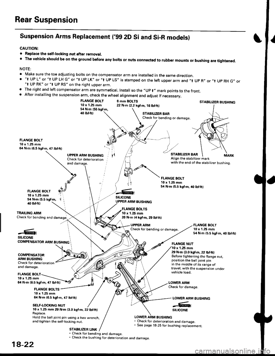
Suspension Arms Replacement ('gg 2D Si and Si-R models)
CAUTION:
. Roplace the self-locking nut after removal.' The vehicle should be on the gtound before any bohs or nuls connected to rubber mounts or bushing are tightened.
NOTE:
' Make sure the toe adjusting borts on the compensator arm are insta|ed in the same direction.. "t UP L" or "t UP LH G" or "t Up LK" or "l Up LS,, is stamped on the left upper arm and ,,t Up R,, or "t Up RH G,,"i UP RK" or "t UP RS" on the right upper arm.. The right and left compensator arm are symmeticar. Install sothe"upr"markpointstothefront.. After installing the suspension arm, check the wheel atignment and adiust if necessary,
FLANGE BOLT'10 x 1.25 mm54Nm155kgl.m,,rc lbf.ftl
8 rhm BOLTS22 N.m {2.2 kgf.m, 16 tbtfrlSTABILIZER BUSHTNG
FLANGE BOLT10 x 1.25 rnm54 N.m {5.5 kgt m, iro lbf.ft)
STAEILIZER BARCheck for bending or damage.
FLANGE BOLT10 x 1 .25 mm64 N m {5.5 kgf.m,47 lbtftl
FLANGE BOLT10 x 1.25 mm54 N.m 15.5 *gf.m,
and
UPPER ARM BUSHINGCheck for deteriorationAlign the stabitizer markwith the end ot the stabilizer bushing.
FLANGE BOLT'10 x 1.25 mm54 N.m 15.5 kgt.m, a0 lbtftl
stLrcoNEUPPER ARM BUSHINGiO lbf.ftl
TRAILING ARMCheck for bending and
EOLTS10 x 1.25 mm39 N m ll kgf.m, 29 lbf.ft)
UPPER ARMCheck for b€nding or damage.#@lstLtcoNECOMPENSATOR ARM BUSHING
COMPENSATORARM BUSHINGCheck for deteriorationand damage.
FLANGE NUTr '1.25 mm29 N.m {3.0 ksl.m,22 lbtft}Belore tightening the flange nut,position the ball joint pinin the middle ol its range oftravel, with the suspension undervehicle load.
LOWER ARMCheck for damage-
BUSHING
FLANGE BOLTl0 x 1.25 mm6l N.m 16.5 kg{.m, a7 lbt.ftl
FLANGE BOLTS10 x 1,25 mm64 N.m {6.5 kgf.m, 47 lbf.ftl
SELF.LOCKNG NUT
LOWER ARM
-GrstltcoNE10 x 1.25 mm 29 N.m (3.0 ksl.m, 22 tbtfrlReplace.Hold the ball ioinl pin using a hex w.enct.and tighten the selfjocking nut.
STABILIZEB LINK
LOWER ARM BUSHING. Check for deterioration and damaoe.' See page 18 25 for bushing replaciement.
' Check for bending and damage.. Check the bushing for deterioration ano oamage.
18-22
Page 1150 of 2189
Rear Damper
Removal
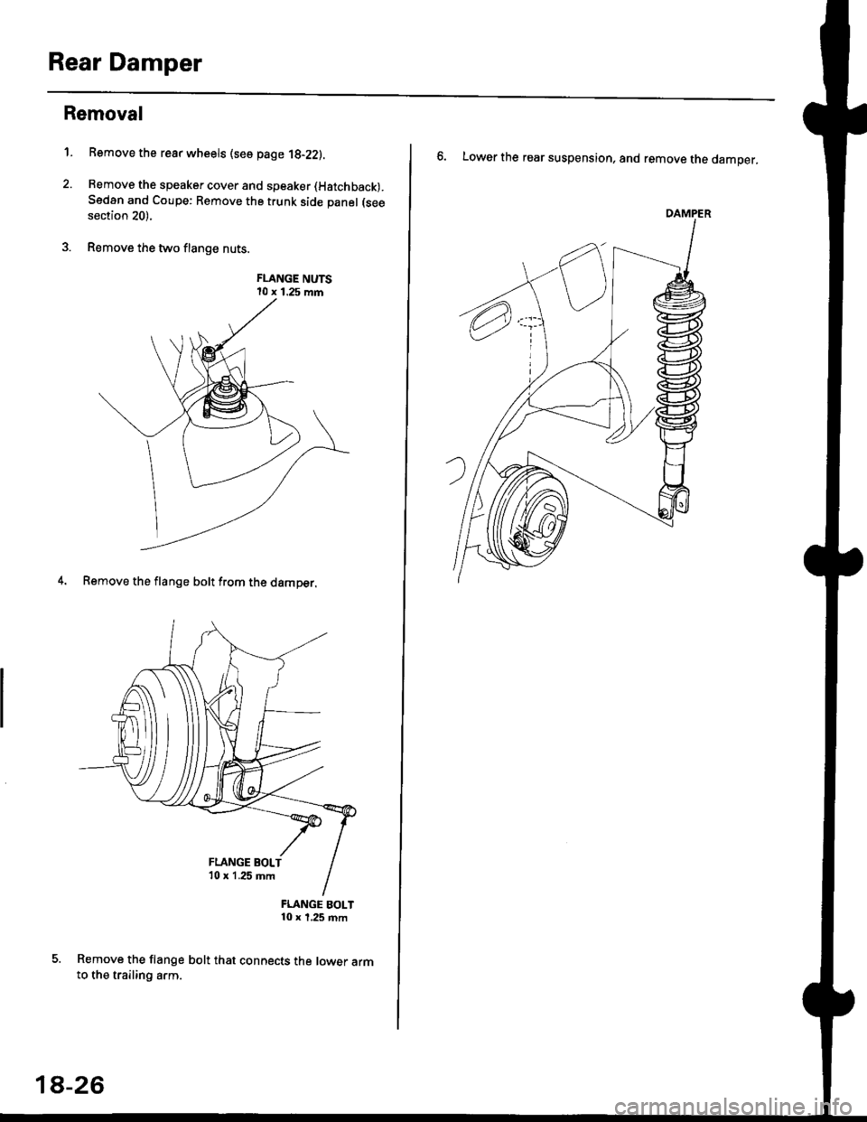
1. Bemove the rear wheels (see page 1g-22).
2. Remove the speaker cover and speaker (Hatchback).
Sedan and Coupe: Remove the trunk side panel (see
section 20).
3. Remove the two flange nuts.
FLANGE NUTS10 x 1.25 mm
4. Remove
FLANGE BOLT10 x 1,25 mm
Remove the flange bolt that connects the lower armto the trailing arm.
the flange bolt from the damper.
FLANGE BOLT'10 x 1 .25 mm
18-26
6. Lower the rear suspension, and remove the damper.
Page 1151 of 2189
IDisassembly/lnsPection
lr
Disassembly
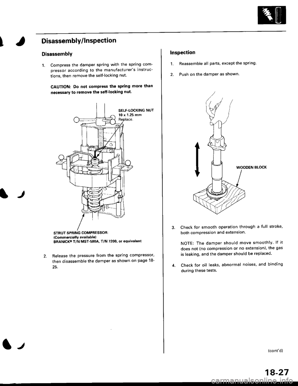
1. Compress the damper spring with the spring com-
pressor according to the manufacturer's instruc-
tions, then remove the self-locking nut.
GAUTION: Do not compress the spring more than
necessary to remove the sell-locking nut.
STNUT SPRING COMPRESSOR:
lComm6rcially .vailablelERANICKo T/N MST-580A, T/N 7200, or equivalent
Release the pressure from the spring compressor.
then disassemble the damper as shown on page 18-
(|-r
lnspection
1. Reassemble all parts, except the sprlng.
2. Push on the damPer as shown.
WOODEN BLOCK
Check for smooth operation through a full stroke,
both compression and extension.
NOTE: The damper should move smoothly lf it
does not (no compression or no extension), the gas
is leaking, and the damper should be replaced.
Check Jor oil leaks, abnormal noises, and binding
during these tests.
{cont'd)
18-27
Page 1153 of 2189
Rear Damper
Ilnstallation
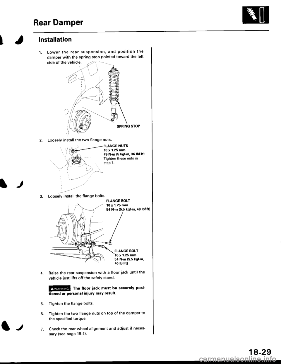
'1. Lower the rear suspension, and position the
damper with the spring stop pointed toward the left
SPRING STOP
2. Loosely installthe two flange nuts
FLANGE NUTS10 x 1.25 mm49 N.m (5 kgf.m, 36 lbt'ft)
Tighten these nuts in
step 7.
lr
3. Loosely install the flange bolts.
FLANGE BOLT10 x 1.25 mm54 N.m {5.5 kgf m, 40 lbt'ft1
FLANGE BOLT10 x 1 .25 mm54 N.m {5.5 kgf.m,/r0 lb{.ft|
7.
Raise the rear suspension with a floor jack until the
vehicle just lifts off the safety stand.
!@@ Tne floor iacx must be securelY Posi-
tionod or peFonal iniury may rssull
Tighten the flange bolts.
Tighten the two flange nuts on top of the damper to
the specified torque.
Check the rear wheel alignment and adjust if neces-
sary (see page 18-4).
1A-29
Page 1156 of 2189
![HONDA CIVIC 1996 6.G Workshop Manual Special Tools
Ref. No. I Tool Numbo]DescriplionOty I Page Reference
o07HAE - SG00100
07JAG - SD40100
07914 - SA50001
Brake Spring Compressor
Pushrod Adjustment Gauge
Snap Ring Pliers
19-28, 33
19-22
o HONDA CIVIC 1996 6.G Workshop Manual Special Tools
Ref. No. I Tool Numbo]DescriplionOty I Page Reference
o07HAE - SG00100
07JAG - SD40100
07914 - SA50001
Brake Spring Compressor
Pushrod Adjustment Gauge
Snap Ring Pliers
19-28, 33
19-22
o](/img/13/6068/w960_6068-1155.png)
Special Tools
Ref. No. I Tool Numbo]DescriplionOty I Page Reference
o07HAE - SG00100
07JAG - SD40100
07914 - SA50001
Brake Spring Compressor
Pushrod Adjustment Gauge
Snap Ring Pliers
19-28, 33
19-22
o@
19-2
Page 1157 of 2189
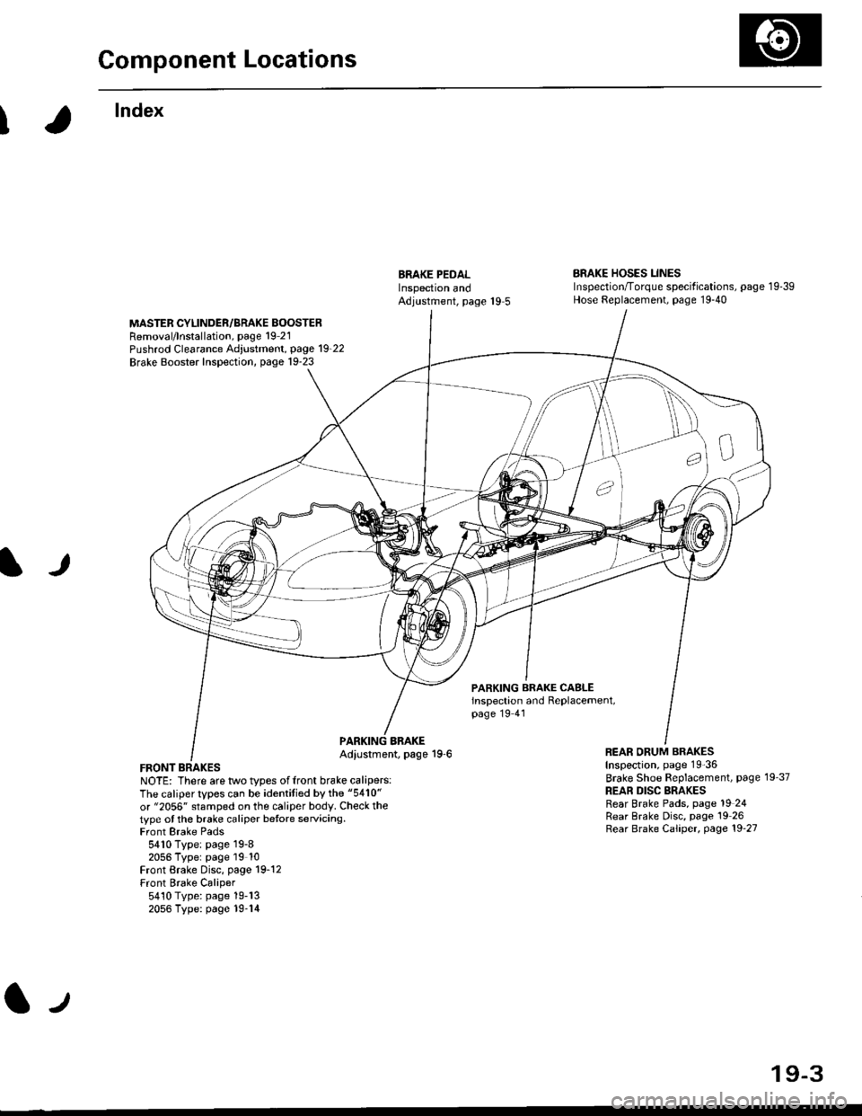
Component Locations
I
lndex
ERAKE PEDALInspectron andAdjustment, page 19 5
BRAKE HOSES LINESInspection/Torque specif ications, page 1 9-39Hose Replacement, page 19-40
MASTER CYLINDER/BRAKE BOOSTERRemoval/lnstallation, page 19 21Pushrod Clearance Adjustment, page 19_22
Brake Booster Inspection, page 19-23
lJ
PARKING BRAKE CASLEinspection and Replacement,page 19 41
FRONT BRAKESNOTE: There are two types offront brake calipers:The caliper types can be identitied by the "5410"
or "2056" stamped on the caliper body. Check thetype ot the brake caliper betore servicing.Front Brake Pads5410 Type: page 19-82056 Typer page 19 10Front Brake Disc, page 19-12Front Brake Caliper5410 Type: page 19-132056 Type: page 19-14
BBAKEAdiustment, page 19-6REAR ORUM BRAKESInspection, page 19-36
Brake Shoe Beplacement, page 19'37
REAR DISC BRAKESRear Brake Pads, page 19 24Rear Brake Disc, page 19 26Rear Brake Caliper, page 19'27
lJ
19-3
Page 1162 of 2189
Front Brake Pads
Inspection and Replacement
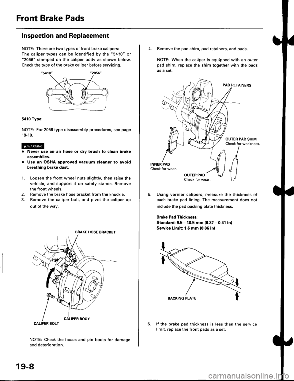
NOTE: There are two types of front brake calipers:
The caliper types can be identified by the "5410" or"2056" stamped on the caliper body as shown below.
Check the type of the brake caliper before servicing.
5i110 Type:
NOTE: For 2056 type disassembly procedures. see page
19-'10.
Never use an air hose or dry brush lo clean brake
assgmblios.
Use an OSHA approved vacuum cleaner to avoid
breathing brake dust.
Loosen the front wheel nuts slightly, then raise the
vehicle, and support it on safety stands. Remove
the front wheels.
Remove the brake hose bracket from the knuckle.
Remove the caliper bolt, and pivot the caliper up
out of the wav.
1.
2.
NOTE: Check the hoses and pin boots for damage
and deterioration.
CALIPER BOLT
19-8
4. Remove the pad shim. pad retainers, and pads.
NOTE: When the caliper is equipped with an outer
pad shim, replace the shim together with the pads
5. Using vernier calipers, measure the thickness of
each brake pad lining. The measurement does not
include the pad backing plate thickness.
Brake Pad Thickno$:
Standard: 9.5 - 10.5 mm 10.37 - 0.41 in)
SerYico Limit 1.6 mm {0.06 in}
lf the brake pad thickness is less than the service
limit, replace the front Dads as a set.
Page 1166 of 2189
Front Brake Disc
Disc Runout Inspection
L
2.
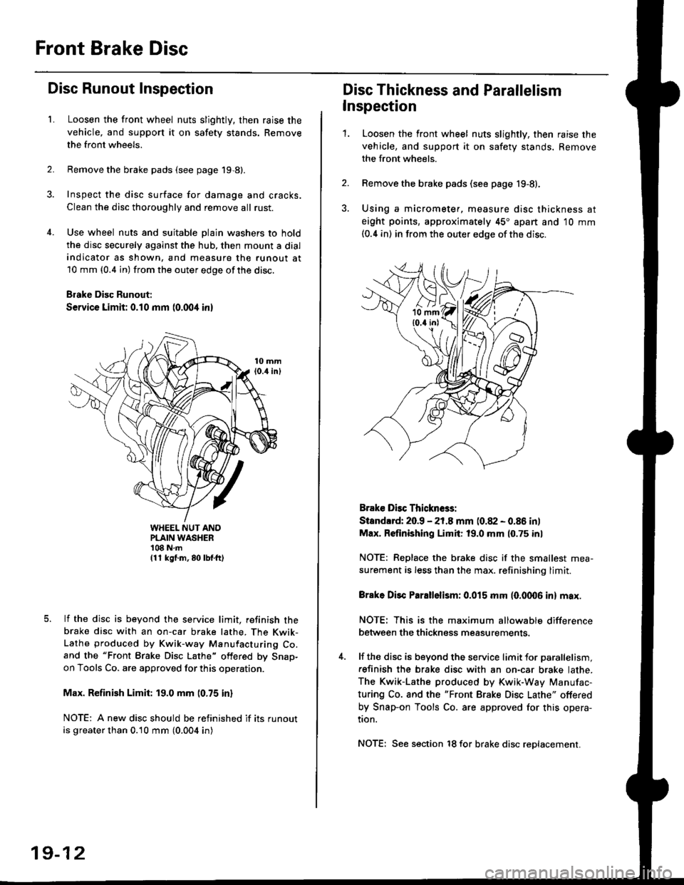
Loosen the front wheel nuts slightly, then raise the
vehicle, and support it on safety stands. Remove
the front wheels.
Remove the brake pads (see page 19,8).
Inspect the disc surface for damage and cracks.
Clean the disc thoroughly and remove all rust.
Use wheel nuts and suitable plain washers to hold
the disc securely against the hub, then mount a dial
indicator as shown, and measure the runout at
10 mm (0.4 in) from the outer edge of the disc.
Brake Disc Runout:
Service Limit: 0.10 mm (0.004 inl
WHEEL NUT ANOPLAIN WASHER'108 N.m(11 kg{.m, 80 lbf.ft)
lf the disc is beyond the service limit, refinish thebrake disc with an on-car brake lathe, The Kwik-Lathe produced by Kwik-way Manufacturing Co.and the "Front Brake Disc Lathe" offered by Snap-on Tools Co. are approved for this operation.
Max. Refinish Limit: 19.0 mm (0.75 in)
NOTE: A new disc should be refinished if its runout
is greater than 0.10 mm (0.004 in)
19-12
Disc Thickness and Parallelism
Inspection
1.Loosen the front wheel nuts slightly, then raise the
vehicle, and support it on safety stands. Remove
the front wheels.
Remove the brake pads (see page 19-8).
Using a micrometer, measure disc thickness at
eight points, approximately 45" apart and 10 mm(0.4 in) in from the outer edge of the disc.
Brake Dbc Thickn6s:
Standlrd: 20.9 - 21.8 mm (0.82 - 0.86 in)
Max. Refinishing Limit: 19.0 mm 10.75 inl
NOTE: Replace the brake disc if the smallest mea-
surement is less than the max. refinishinq limit.
Brake Disc Parallelism: 0.015 mm (0.fit06 in) max.
NOTE: This is the maximum allowable difference
between the thickness measurements.
lf the disc is beyond the service limit for parallelism,
refinish the brake disc with an on-car brake lathe.
The Kwik-Lathe produced by Kwik-Way Manufac-
turing Co. and the "Front Brake Disc Lathe" offered
by Snap-on Tools Co. are approved for this opera-
tion.
NOTE: See section 18 for brake disc reDlacement.
Page 1167 of 2189
Front Brake Caliper
It
Disassembly
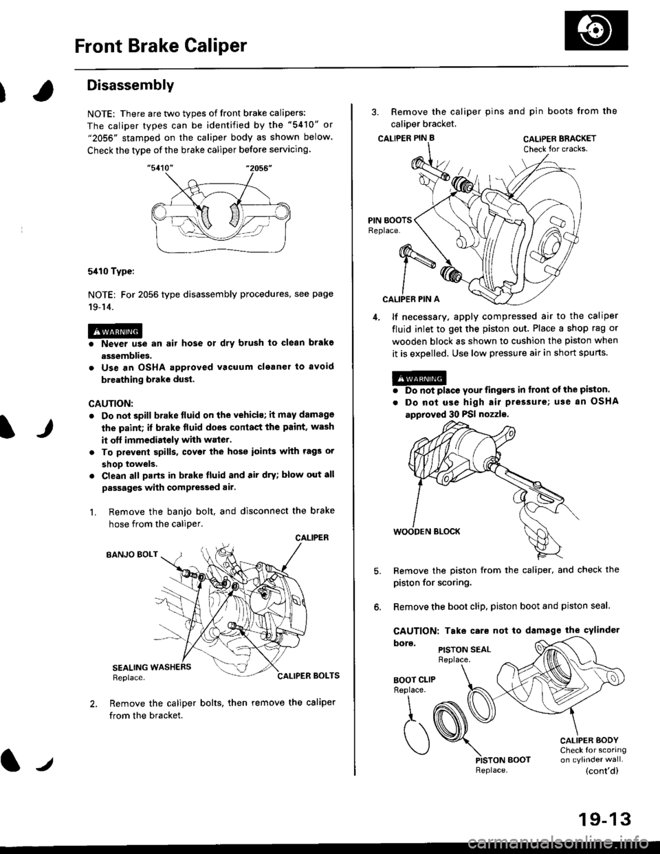
NOTE: There are two types of front brake calipers:
The caliper types can be identified by the "5410" or"2056" stamped on the caliper body as shown below.
Check the type of the brake caliper before servicing.
5410 Type:
NOTE: For 2056 type disassembly procedures, see page
19-14.
@o Never use an air hose ot dry brush to clean brakg
assemblies.
. Use an OSHA approved vacuum clganer to avoid
breathing brake dust.
CAUTION:
. Do not spill brake lluid on the vehicls; it may damage
the paint; if brake fluid does conlact the paint, wash
it off immedistely with waier.
. To prevenl spills, covet the hose ioin$ with rags or
shop towels.
. Clean all parts in brake fluid and air dry; blow out all
passages with compressed air.
L Remove the banjo bolt, and disconnect the brake
hose from the caliDer.
CALIPER
BANJO EOLT
SEALINGReplace.BOLTS
Remove the caliper bolts, then remove the caliper
from the bracket.
lJReplace.
3. Remove the caliper pins and pin boots from the
calioer bracket,
CALTPER PIN B CAL|PER BRACKET
CALIPER PIN A
4, lf necessary. apply compressed air to the caliper
fluid inlet to get the piston out. Place a shop rag or
wooden block as shown to cushion the piston when
it is expelled. Use low pressure air in short spurts.
@. Do not place your iingers in tront ol the piston.
. Do not use high air pressure; use 8n OSHA
approved 30 PSI nozzls,
Remove the piston from the caliper, and check the
piston for scoring.
Remove the boot clip, piston boot and piston seal.
CAUTION: Take care not to damage the cylindcr
PISTON SEALReplace.
BOOT CLIPReplace.
\,
,t. (
)PISTON BOOT
CALIPER BODYCheck for scoring
(cont'd)
19-13
Page 1170 of 2189
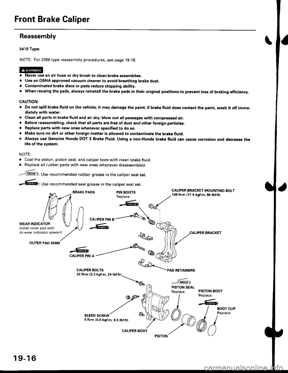
Front Brake Galiper
Reassembly
5410 Type:
NOTE: For 2056 type reassembly procedures, see page 19-18.
o Never use an air hose or dry brush to clean brako assemblies.. Use an OSHA approved vacuum cleanerto avoid breathing brake dust.. Contaminated brake discs or pads reduce stopping abilhy.. when reusing the pads, always reinstall the brake pads in their original positions to pr€vent loss of braking €fficiency.
CAUTION:
. Do not spill brake fluid on the vehicle; it may damage the paint; if brake fluid do€s contaci the psint, wash it oft imme"diately with water.
. Clean all parts in brake fluid and air dry; blow out all passag€s whh comp.€ssed air.. Betore reassembling, check that all parts are free ol dust and othor toreign particlos.
. Replace parts wilh new ones whenever specified to do so.. Make sure no dirt or other toreign matt€r is allowed to contaminate the brake fluid.. Always use Genuine Honda DOT 3 Brake Fluid. Using a non.Honda brake tluid can cause corrosion and decresse thelife of th€ system.
NOTE:
. Coat the piston, piston seal, and caliper bore with clean brake fluid.. Replace all rubber parts with new ones whenever disassembled.
z_..=-.q8! .9!,H: Use recommended rubber grease in the caliper seal set.
-.61' use recommended seal grease in the catiper seal set.
BRAKE PADSPIN BOOTSReplace.
OUTER PAD SHIM
-o -'''---&@CAI-IPER PIN A -
BLEED SCREWS N.m (0.9 kgt.m, 6.5 tbf.ftl
"k..6
*/\*
car-rpen prr'r e-....,-q\,
-W@{
q
1
PAD RETAINERS
CALIPER BRACKET
WEAB INDICATOR
tilfliltn
tw tfi lJlWEAB rNDrcAroR \J I Ilnsrall inner pad with lAVirs weat indicatot !pwatd/,.
CALIPER BRACKEI MOUNTING BOLT108 N.m {11.0 kgt m,80lbf.ft)
PISTON BOOTReplace.
-6r
/ eoor cr-re
I neptace.
6/vo
PISTON SEALReplace.
19-16
CALIPER BODY