Lights HONDA CIVIC 1996 6.G Repair Manual
[x] Cancel search | Manufacturer: HONDA, Model Year: 1996, Model line: CIVIC, Model: HONDA CIVIC 1996 6.GPages: 2189, PDF Size: 69.39 MB
Page 1639 of 2189
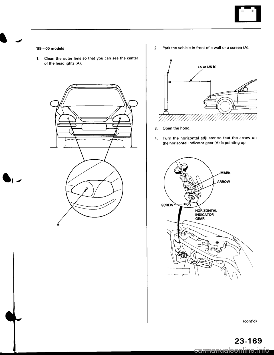
'99 - 00 models
1. Clean the outer lens so that you can see the center
of the headlights (A).
l,-
2. Park the vehicle in front of a wall or a screen (A).
A
4.
Open the hood.
Turn the horizontal adjuster so that the arrow on
the horizontal indicator gear (A) is pointing up.
7.5 m (25 ft)
Page 1640 of 2189
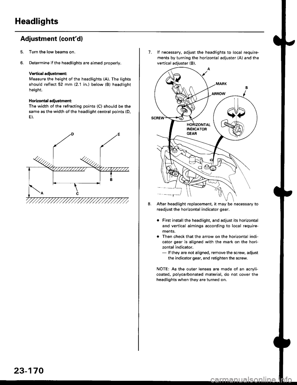
Headlights
Adjustment (cont'dl
Turn the low beams on.
Determine if the headlights are aimed properly.
Vsrtical adiustmsnt:
Measure the height of the headlights (A). The lights
should reflect 52 mm \2.1 in.) below (B) headlight
height.
Horizontal adi$tment:
The width of the refracting points (C) should be the
same as the width of the headlight central points (D,
23-170
7. lf necessary, adjust the headlights to local require-
ments by turning the horizontal adjuster (A) and the
vertical adjuster (B).
After headlight replacement, it may be necessary to
readjust the horizontal indicator gear.
. First installthe headlight, and adjust its horizontal
and vertical aimings according to local require-
ments.
. Then check that the arrow on the horizontal indi-
cator gear is aligned with the mark on the hori-
zontal indicator,- lf they are not aligned, remove the screw, adjust
the indicator gear, and retighten the screw.
NOTE: As the outer lenses are made of an acryli-
coated, polycarbonated material, do not cover the
headlights when they are turned on.
Page 1641 of 2189
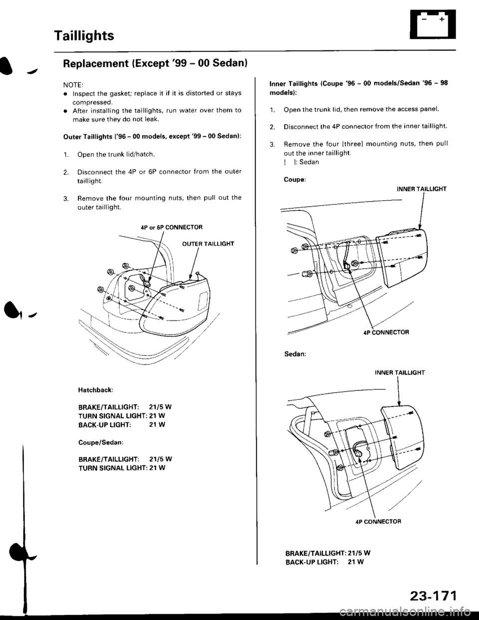
Taillights
Replacement (Except'99 - 00 Sedanl
NOTE:
. Inspect the gasket; replace it il it is distorted or stays
compressed.
. After installing the taillights, run water over them to
make sure they do not leak.
Outer Taillights ('96 - 00 models, except'99 - 00 Sedan):
1. Open the trunk lid/hatch.
2. Disconnect the 4P or 6P connector trom the outer
taillight.
3. Remove the four mounting nuts, then pull out the
outer taillight.
l-
Hatchback:
BRAKE/TAILLIGHT: 2115W
TURN SIGNAL LIGHT: 21 W
BACK-UP LIGHT: 21 W
4P or 6P CONNECTOR
BRAKE/TAILLIGHT: 2115W
TURN SIGNAL LIGHT: 21 W
BRAKEiTAILLIGHT: 2115 W
BACK-UP LIGHT: 21 W
Inner Taillights (Coupe'96 - 00 models/Sedan'96 - 98
models):
1. Open the trunk lid, then remove the access panel.
2. Disconnect the 4P connector from the inner taillight.
3. Remove the four [three] mounting nuts, then pull
out the inner taillight.
I l: Sedan
Coupei
INNER TAILLIGHT
Sedan:
INNER TAILLIGHT
4P CONNECTOB
Page 1642 of 2189
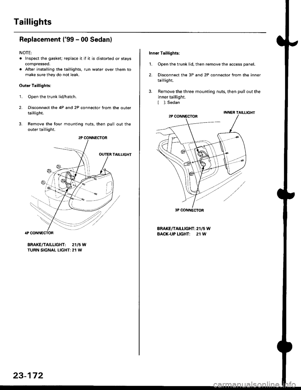
Taillights
Replacement ('99 - 00 Sedanl
NOTE:
. Inspect the gasket; replace it if it is distorted or stays
compressed.
. After installing the taillights, run water over them to
make sure they do not leak.
Outer Taillights:
1. Open the trunk lid/hatch.
2. Disconnect the 4P and 2P connector trom the outer
taillight.
3. Remove the four mounting nuts, then pull out the
outer taillight.
TAILLIG}fi
4P CONNECTOR
BRAKE/TAILLIGHT: 2115W
TURN SIGNAL LIGHT: 21 W
r*i/et./
23-172
Inner Taillights:
'1. Open the trunk lid, then remove the access panel.
2. Disconnect the 3P and 2P connector from the inner
taillight.
3. Remove the three mounting nuts, then pull out the
inner taillight.
[ ]: Sedan
BRAKE/TAILLIGHT: 2r15 W
BACK.UP LIGHT: 21 W
3P CONNECTOR
Page 1644 of 2189
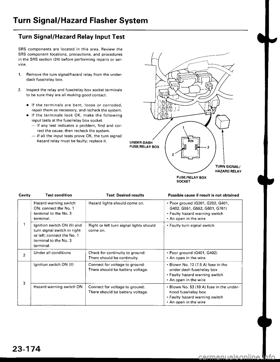
Turn SignallHazard Flasher System
1.
Turn Signal/Hazard Relay Input Test
SRS components are located in this area. Review the
SRS component locations, precautions, and procedures
in the SRS section {24} before performing repairs or ser-
vice.
Remove the turn signal/hazard relay from the under-
dash fuse/relay box.
Inspect the relay and fuse/relay box socket terminals
to be sure they are all making good contact.
. lf the terminals are bent, loose or corroded,
repair them as necessary, and recheck the system.
. lf the terminals look OK, make the following
input tests at the fuse/relay box socket.- lf any test indicates a problem, find and cor-
rect the cause, then recheck the system.- lf all the input tests prove OK, the turn signal/
hazard relay must be faulty; replace it.
Test: Desired results
FUSE/RELAY BOXSOCKET
Possible cause it result is not obtainedCavityTest condition
8Bffii
\_t-E rl.]l
| - lll
n'rl
,.ff T-'t:
Hazard warning switch
ON; connect the No. 1
terminal to the No.3
rermtnat.
Hazard lights should come on.Poor ground \G201, G202, G401,
G402, Gs51, G552, G601, G761)
Faulty hazard warning switch
An open in the wire
lgnition switch ON (ll) and
turn signal switch in right
or left; connect the No. 1
terminal to the No. 3
terminal.
Right or left turn signal lights should
come on.
. Faulty turn signal switch
2Under allconditionsCheck for continuity to ground:
There should be continuity.
. Poor ground (G401, G402). An open in the wire
3
lgnition switch ON (ll)Connect for voltage to ground:
There should be battery voltage.
Blown No. '12 (7.5 A) fuse in the
under-dash fuse/relay box
Faulty hazard warning switch
An open in the wire
Hazard warning switch ONConnect for voltage to ground:
There should be battery voltage.
Blown No. 53 (10 A) fuse in the under-
hood fuse/relay box
Faulty hazard warning switch
An open in the wire
23-174
Page 1646 of 2189
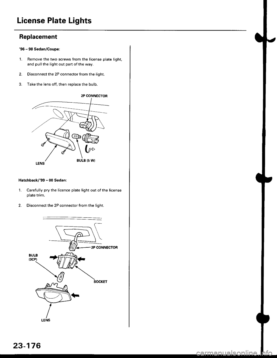
License Plate Lights
Replacement
'96 - 98 Sedan/Coupe:
L Remove the two screws from the license plate light,
and pull the light out pan ot the way.
2. Disconnect the 2P connector trom the light.
3. Take the lens off, then replace the bulb.
Hatchback/'gg - 00 Sedan:
1. Carefully pry the licence plate light out of the license
plate tnm.
2. Disconnect the 2P connector from the light.
2P CONNECTOR
2P CONNECTOR
23-176
Page 1647 of 2189
![HONDA CIVIC 1996 6.G Repair Manual Back-up Lights
Circuit Diagram
]GN TIONSWITCH
*HT/BLK +*HT*;L BLKTYEI-"--""\-z-
I
fTil"liUiEEs,x,
YEURED
fr
l$*,l
YEL
l^ .0.,. ,,
rb !fi+l
Y(ififrr-)
I
tcroseo n rosrron El
GRNi BLKq-,
UNOER HONDA CIVIC 1996 6.G Repair Manual Back-up Lights
Circuit Diagram
]GN TIONSWITCH
*HT/BLK +*HT*;L BLKTYEI-"--""\-z-
I
fTil"liUiEEs,x,
YEURED
fr
l$*,l
YEL
l^ .0.,. ,,
rb !fi+l
Y(ififrr-)
I
tcroseo n rosrron El
GRNi BLKq-,
UNOER](/img/13/6068/w960_6068-1646.png)
Back-up Lights
Circuit Diagram
]GN TIONSWITCH
*HT/BLK +*HT*;L BLKTYEI-"--""\-z-
I
fTil"liUiEEs,x','
YEURED
fr
l$*,'l
YEL
l^ .0.,. ,,
rb !'fi+l'
Y(ifi'frr-')
I
tcroseo' n rosrron El
GRNi BLKq-,
UNOER HOOD FUSE/RELAY BOX
23-177
Page 1648 of 2189
![HONDA CIVIC 1996 6.G Repair Manual Brake Lights
WNT/GRN
Circuit Diagram
UNDEH HOODFUSEiRELAYBOXBATTERY/-l I No s2 (1sA) |
u/T\--]-wHrGFNTwfciN_l
tvHORN SYSTEM
INNERTAILL]GHT
GRNMHT
I
AE-ii,t
Yut#l
IBLK
ffi; I
I l,"l
I Ii
Li;
GRN,4f HONDA CIVIC 1996 6.G Repair Manual Brake Lights
WNT/GRN
Circuit Diagram
UNDEH HOODFUSEiRELAYBOXBATTERY/-l I No s2 (1sA) |
u/T\--]-wHrGFNTwfciN_l
tvHORN SYSTEM
INNERTAILL]GHT
GRNMHT
I
AE-ii,t
Yut#l
IBLK
ffi; I
I l,"l
I Ii
Li;
GRN,4f](/img/13/6068/w960_6068-1647.png)
Brake Lights
WNT/GRN
Circuit Diagram
UNDEH HOODFUSEiRELAYBOXBATTERY/-l I No s2 (1sA) |
u/T'\--]-wHrGFNTwfciN_l
tvHORN SYSTEM
INNERTAILL]GHT
GRNMHT
I
AE-'ii,t
Yut#l
IBLK
ffi; I
I l,"l
I I''i
Li;
GRN,4fiHT
l**,,,,I P } BRAKE
Y ilT'
I
I
I
IgLK
I
I:
flatchbackCoupe/SedanSedan 99 mode
ffi; I
i $*i
iri
Li*'']
GRNMHT
I
A b'rt^t-,
Yllf,ll
IBLK
BLK
I
I
I
G601 r Halchback/Coupe/Sedan
BLK
II
II
I
G601 : Haldbackiooup€/Sedan G761 :G601 :G602 :
+ 21W :Coup€/Sedan18W :HalchbackJ I : Wilh cruise control
23-178
Page 1650 of 2189
![HONDA CIVIC 1996 6.G Repair Manual Dash Lights Brightness Controller
UNDEF.DASHFUSEi RELAY 8OX
|-;il;I-l-*-Tl
I
IREDi 8LK
cotvBiNATloNLIGHT SW]TCH
Circuit Diagram
,4.wHT -tlf- RED/GBN
UNDEF HOOD FUSE/RELAY BOX
23-180
G401G402 HONDA CIVIC 1996 6.G Repair Manual Dash Lights Brightness Controller
UNDEF.DASHFUSEi RELAY 8OX
|-;il;I-l-*-Tl
I
IREDi 8LK
cotvBiNATloNLIGHT SW]TCH
Circuit Diagram
,4.wHT -tlf- RED/GBN
UNDEF HOOD FUSE/RELAY BOX
23-180
G401G402](/img/13/6068/w960_6068-1649.png)
Dash Lights Brightness Controller
UNDEF.DASHFUSEi RELAY 8OX
|-;il;I-l-*-Tl
I
IREDi 8LK
cotvBiNATloNLIGHT SW]TCH
Circuit Diagram
,4.wHT -tlf- RED/GBN
UNDEF HOOD FUSE/RELAY BOX
23-180
G401G402
Page 1651 of 2189
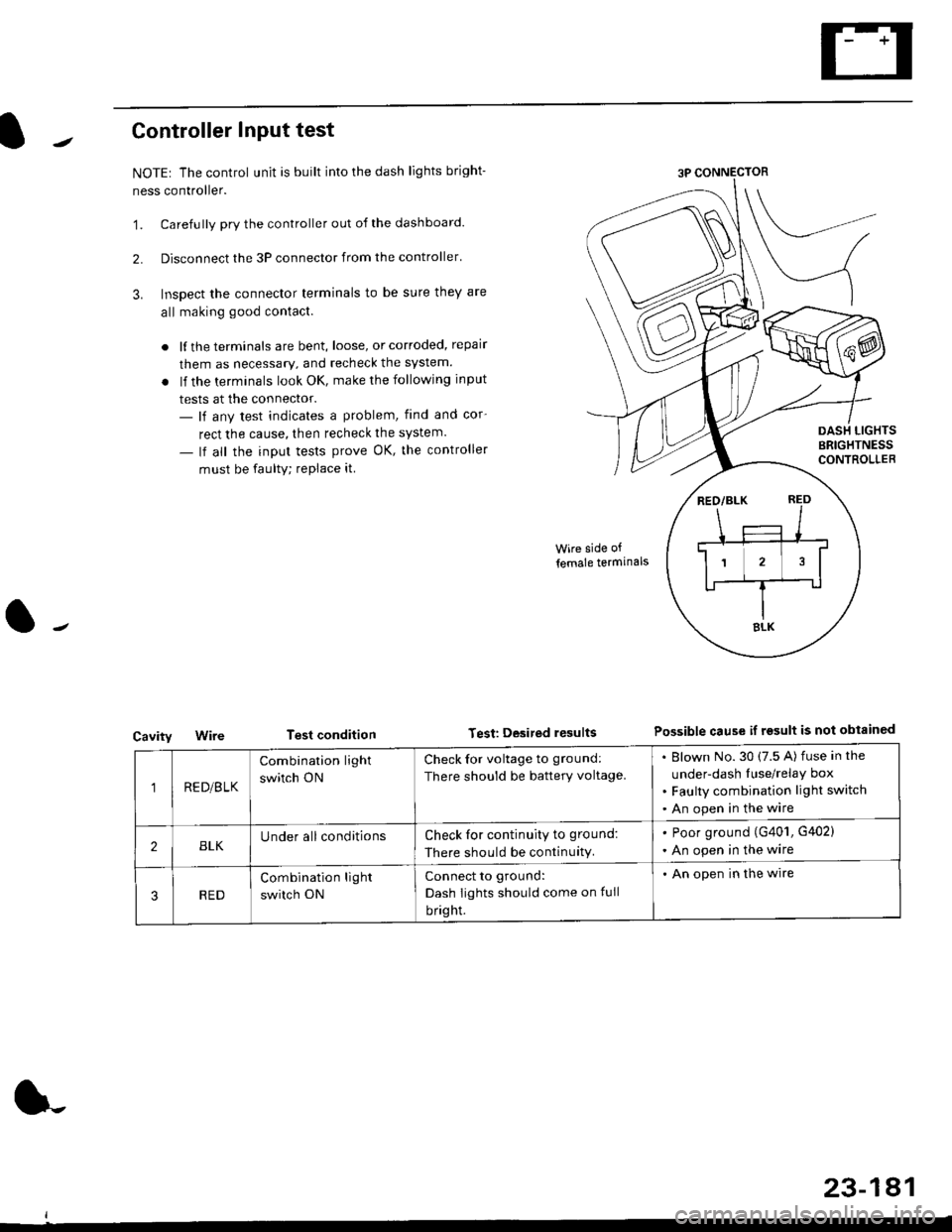
Controller Input test
NOTEr The control unit is built into the dash lights bright-
ness controller.
'1. Carefully pry the controller out of the dashboard.
2. Disconnect the 3P connector from the controller'
3. Inspect the connector terminals to be sure they are
all making good contact.
. lf the terminals are bent, loose, or corroded, repair
them as necessary, and recheck the system.
. lf the terminals look OK, make the following input
tests at the connector.- lf any test indicates a problem, find and cor-
rect the cause, then recheck the system.
- lf all the input tests prove OK, the controller
must be faulty; replace it
Cavity
Wire side of
lemale termlnals
Test condition Test Desited resultsPossible cause if rgsult is not obtainGd
1RE D/B LK
Combination light
switch ON
Check for voltage to ground:
There should be battery voltage.
Blown No.30 (7.5 A) fuse in the
under-dash Iuse/relay box
Faulty combination light switch
An open in the wire
2BLKUnder all conditionsCheck for continuity to ground:
There should be continuity.
. Poor ground (G401, G402)
. An open in the wire
RED
Combination light
switch ON
Connect to ground:
Dash Iights should come on full
bright.
. An open in the wire
23-181