Lights HONDA CIVIC 1996 6.G Service Manual
[x] Cancel search | Manufacturer: HONDA, Model Year: 1996, Model line: CIVIC, Model: HONDA CIVIC 1996 6.GPages: 2189, PDF Size: 69.39 MB
Page 1607 of 2189
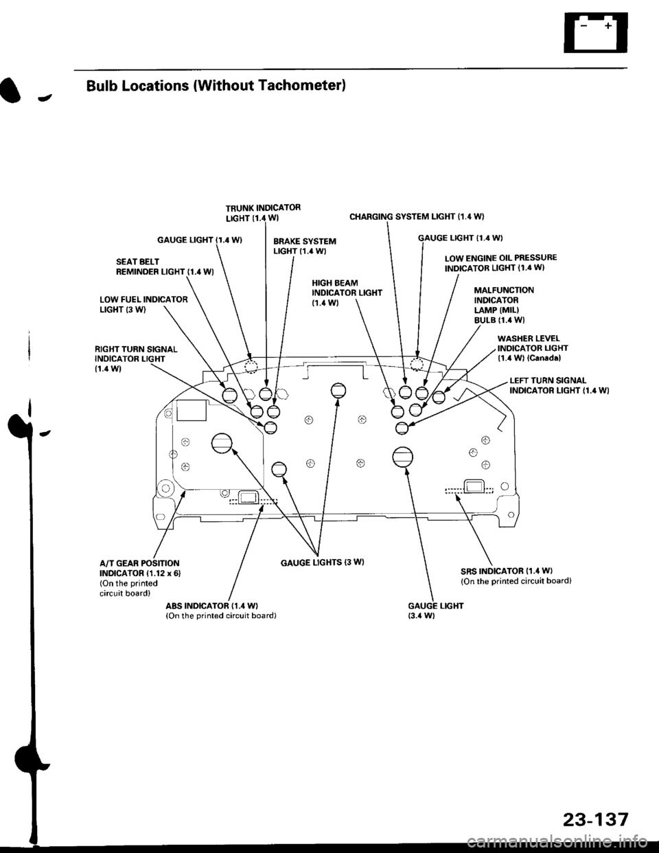
JBulb Locations {Without Tachometer)
TRUNK INDICATORLIGHT {1.i1W}
.4 Wl
CHARGING SYSTEM LIGHT 11,4 W}
LTGHT (1.4 W)GAUGE LIGHT
SEAT BELTREMINDER LIGHT (1.4 WI
LOW ENGINE OIL PRESSUBE
INDICATOB LIGHT (1.4 WI
LOW FUEL INDICATORLrGl{T (3 W)
RIGHT TURN SIGNALINOICATOR LIGHT
(1.1Wt
GAUGE LIGHTS {3 WI
WASHER LEVELINDICATOR LIGHT{1.4 W} lcanad.l
HIGH BEAMINDICATOR LIGHTMALFUNCTIONINDICATORLAMP (MIL)
BULB {1.4 WI
{1.ilW)
LEFT TURN SIGNALINDICATOR LIGHT {1.4 WI
A/T GEAR POSITIONINDICATOR (1.12 x 6)(On the printed
circuit board)
sRs TND|CATOR 11.4 W)
{On the Drinted circuit board}
aBs tNDtcAToR t1.4 W)(On the printed circuit board)(3.{ Wt
o/ o \7 o
23-137
Page 1623 of 2189
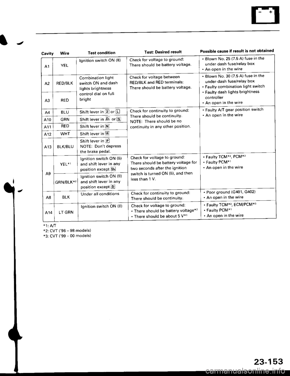
Test conditionTest: Desired resultPossible cause it result is not obtainedCavity
AIYEL
lgnition switch ON (ll)Check for voltage to ground:
There should be banerY voltage.
. Blown No.25 (7.5 A) fuse in the
under dash fuse/relay box
. An open in the wire
A2RED/BLK
Combination light
switch ON and dash
lights brightness
control dial on full
bright
Check for voltage between
RED/BLK and RED terminals:
There should be batterY voltage.
Blown No. 30 {7.5 A) fuse in the
under-dash tuse/relay box
Faulty combination light switch
Faulty dash lights brightness
controller
An open in the wireA3RED
BLUShift lever in P or ICheck for continuity to ground:
There should be continuitY
NOTE: There should be no
continuity in anY other Position.
. Faulty A/T gear Position switch
. An open in the wire
A10GRNShift lever in E or E
A11REDShift lever in E
412WHTShift lever in E
A13BLK/BLU
Shift lever in E
NOTE: Don't depress
the brake pedal.
A9
YEL+ ]lgnition switch ON (ll)
and shift lever in any
position except Pi
Check for voltage to ground:
There should be battery voltage for
two seconds after the ignition
switch is turned ON (ll), and then
less than 'l V.
Faulty TCM*'�, PCM*3
Faulty PCM*r
An open in the wire
GRN/err*'
lgnition switch ON {ll)
and shift lever in anY
position except E
A8BLKUnder all conditionsCheck for continuitv to ground:
There should be continuitY.
. Poor ground (G401, G402)
. An open in the wire
414LT GRN
lgnition switch ON (ll)Check for voltage to ground:
. There should be baftery voltage*'�
. There should be about 5 V*r
Faulty TCM*'�, ECM/PCM*'
Faulty PCM*1
An open in the wire
*2: CVT ('96 - 98 models)*3r CVT ('99 - 00 modelsl
23-153
Page 1630 of 2189
Integrated Gontrol Unit
Input Test (cont'dl
A8--------.--all
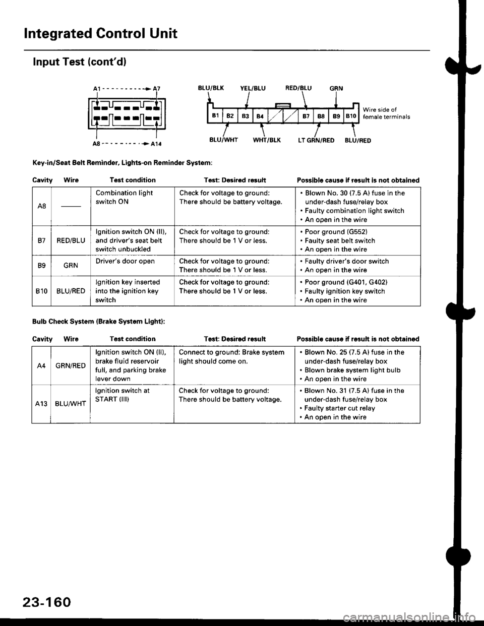
Key-in/Seat Belt R€mind€r, Lights-on Reminder Systom:
Cavity WireTest condhion
Bulb Check System (Brako System Light):
Cavity WireTest condilion
Tost: D€sirod r€guh
T6st: Dosirad result
Possible cause if result is not obtained
Possibls cause if rasuft b not obtainod
A8
Combination light
switch ON
Check for voltage to ground;
There should be battery voltage.
Blown No.30 (7.5 A)fuse in the
under-dash fuse/relay box
Faulty combination light switch
An open in the wire
B7RED/BLU
lgnition switch ON (ll),
and driver's seat belt
switch unbuckled
Check for voltage to ground:
There should be 1 V or less.
Poor ground (G552)
Faulty seat belt switch
An open in the wire
B9GRNDriver's door openCheck for voltage to ground:
There should be 1 V or less.
. Faulty driver's door switch. An open in the wire
Bl0BLU/RED
lgnition key inserted
into the ignition key
switch
Check for voltage to ground:
There should be 1 V or less.
Poor ground (G401. G402)
Faulty ignition key switch
An open in the wire
A4GRN/RED
lgnition switch ON {ll),
brake fluid reservoir
full, and parking brake
tever oown
Connect to ground: Brake system
light should come on.
Blown No.25 (7.5 Alfuse in the
under-dash fuse/relay box
Blown brake system light bulb
An open in the wire
A13BLUA/1r'HT
lgnition switch at
START (III)Check for voltage to ground:
There should be battery voltage.
Blown No.31 (7.5 A) fuse in the
under-dash fuse/relay box
Faulty starter cut relay
An open in the wire
23-160
Page 1631 of 2189
Lighting System
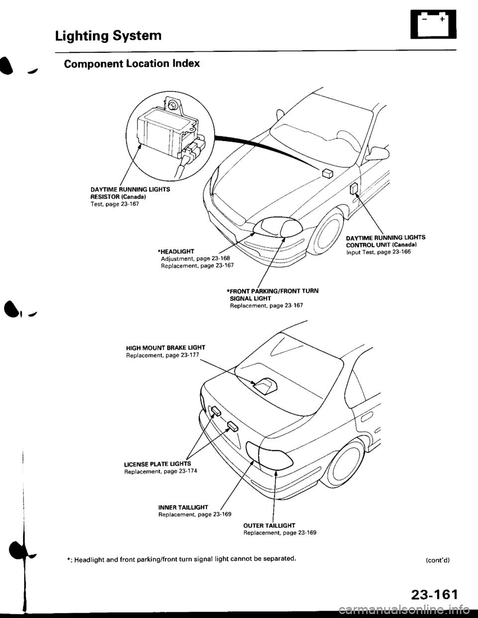
Component Location Index
DAYTIME RUNNING LIGHTSRESISTOR {Canada)Test, page 23 167
DAYTIME RUNNING LIGHTS
CONTROL UNIT (Canadal
Input Test, Page 23 166*HEADLIGHT
Adiustment, page 23-168Replacement, page 23-167
SIGNAL LIGHTReplacement, page 23 167
HIGH MOUNT BRAKE LIGHT
Replacement, page 23-177
LICENSE PLATE LIGHTS
Replacement, Page 23'174
INNER TAILLIGHTReplacement, page 23-169
OUTER TAILLIGHTReplacement, page 23 I69
*: Headlight and front parking/front turn signal light cannot be separated.(cont'd)
23-161
Page 1632 of 2189
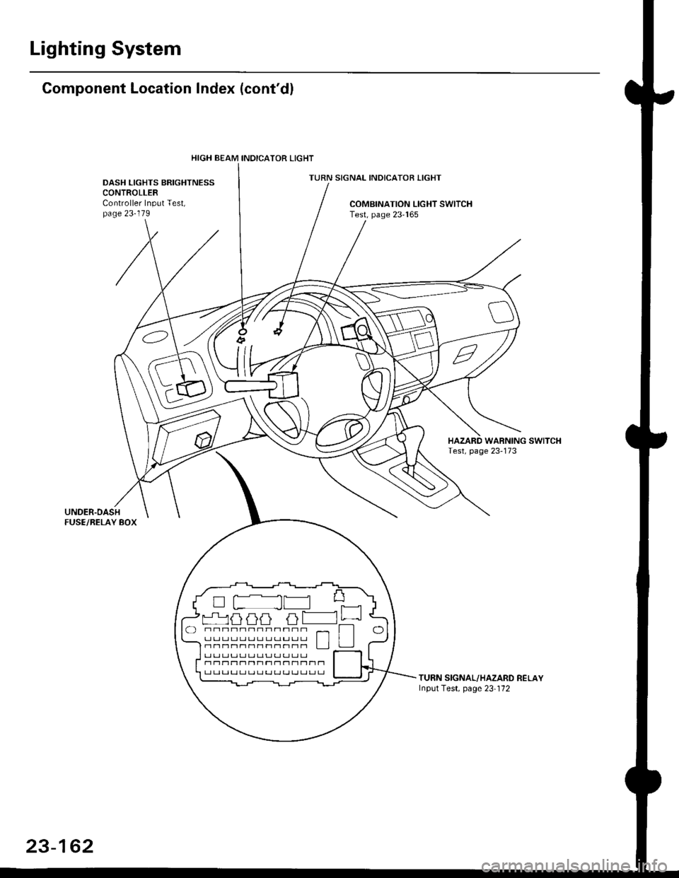
Lighting System
Gomponent Location Index (cont'dl
TURN SIGNAL INDICATOR LIGHTDASH LIGHTS BRIGHTNESSCONTROLLERController Input Test,page 23-119COMBINATION LIGHT SWITCHTest, page 23'165
TURN SIGNAL/HAZARD RELAYInput Test, page 23-'172
HIGH BEAM INOICATOR LIGHT
L ILI LILI LT
rr Lr rJ|r LJ Lr Lr rr !.r rr Lr rr I l-nnr1nr1r1r1r1|-1nn L JJ
r1 n11t'1n Ttr1 r1 - 11 t-1Tt-l T1r-t L.l Lt r-t r-t LJ ! ! LJ LJ ! LJ !J r-l
23-162
Page 1633 of 2189
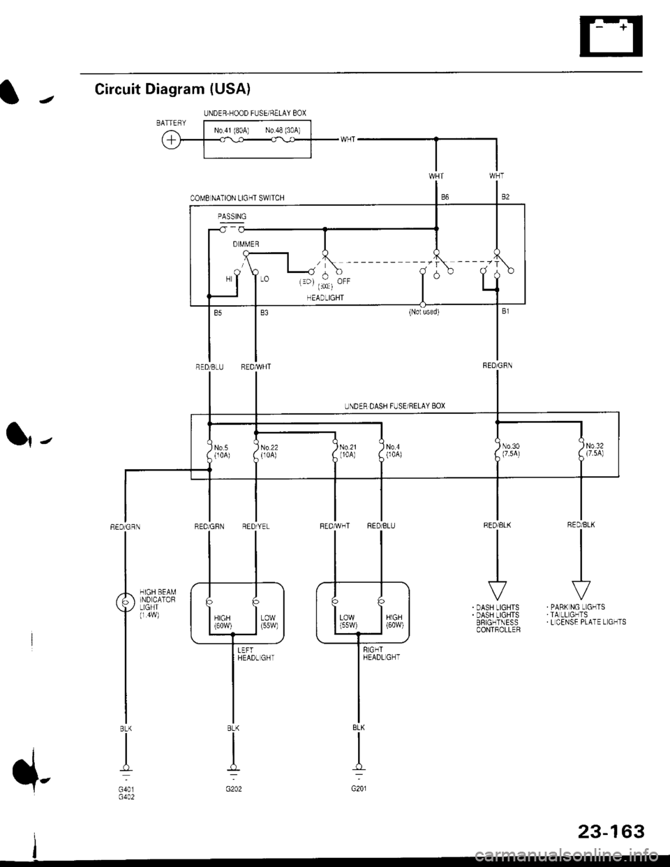
Circuit Diagram (USA)
l|-
RED/BLK
II
I
\?
PABK NG LIGHTSTA LL GHTSL CENSE PLATE L GHTS
RED/ELK
III
I
r'
DASH LIGHTSDASH LIGHTSERIGHTNESSCONTROLLER
HIGH BEAMIND CATORLIGHT(r 4w)
REDiGRN
I
BLK
I
G401G4A2
UNDER,HOOD FUSEi NELAY 8OX
'------ --.-r ----.'r
-T
I" T,,: i.. T
o
UNDER DASH FUSE/RELAY 8OX
No5(104)No.4004)No 30(7.5A)
I)N0.32A {7.5A)
I
No 22(r0A)
AT
lilffl (
II
BLK
I
G201
8LK
I
:
G202
23-163
Page 1634 of 2189
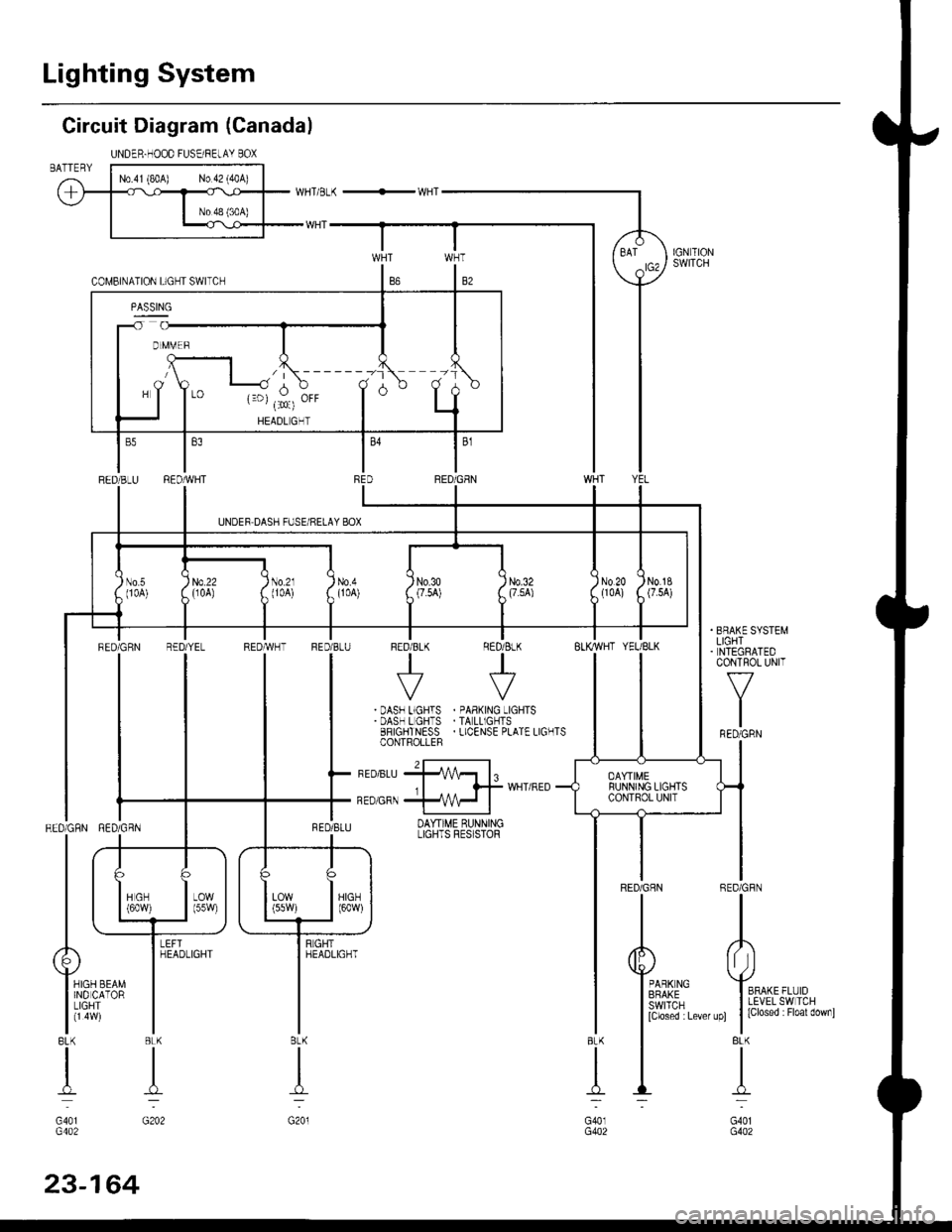
Lighting System
Circuit Diagram (Canada)
UNDER.HOOD FUSEi RELAY BOXBATTERY
BFAKE SYSTEMLIGHTNTEGRATEDCONTROL UNIT
f-7
I
IFED/GRN
REDiGFN
II
o
Yro*, ,,r'oI LEVEL SW TCH
t |
lclosed : Floal downl
BLK
I
-L..
G401G402
T
.:
BLK
n:
G40lG402
BLK
I
G201
RED/GRN RED/GBN
| .+_
ttL
| | las*,
| \_i-f
Alr
Y,o" r.o" I
liiqff'- |BLK BLK
tl
dT--
G401 G202G402
l\------tr -1
d,$,E" T d
RED/BLU RED/REDiGEN
UNDEF DASH FUSE/RELAY BOX
I
)) N0.20tl0Al)'
No.1g(7.5A)No.50 0A)
, ll-l
llltti /i[ii i,II
ll
llri, zll",ll iu"x
TT
FEDiGRN R€D
tl
!-tl--l
ttuLj
il]-
YEL REDTWHT FED/BLU FED/8LK RED/ BLK
tt++
IIVV| | .DASF L.GHTS . oAB(^rG -TGHTSI I .DAS-LGH'S.TALL'GCTS
| | 33''9+il4[','o L.ENSEoLATELTG'TS
I l-,ro,u,rffl,
^-^^-.*^,{*"'"0-
tlI qsnlq,rr DAYT'ME qUNNINGLIGHTS FES STOF
nd--f)
irt* | | Trt* Iorr Itt I---J \---J-------J
-rGHr
lt*"','
I
I
YEL/BLK
DAYTIMERUNNING LIGHTSCONTROL UNIT
RED/GHN R
I
5
[i.mi:-",,,
Page 1636 of 2189
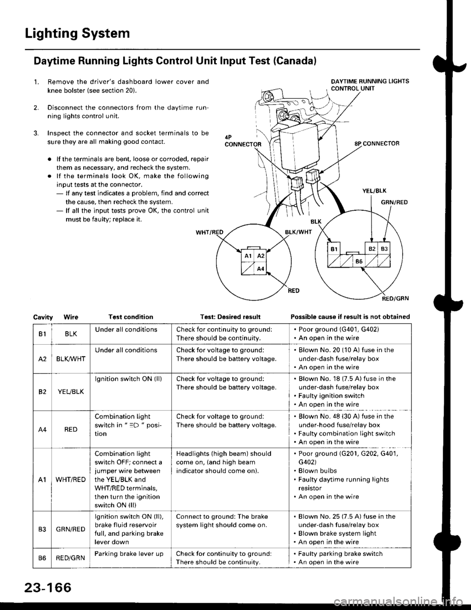
Lighting System
Daytime Running Lights Control Unit Input Test (Canadal
2.
3.
LRemove the driver's dashboard lower cover and
knee bolster (see section 20).
Disconnect the connectors from the daytime run-
ning lights control unit.
Inspect the connector and socket terminals to be
sure they are all making good contact.
lf the terminals are bent, loose or corroded. repair
them as necessary, and recheck the system.
lf the terminals look OK, make the following
input tests at the connector,- lf any test indicates a problem, find and correct
the cause, then recheck the system.- lf all the input tests prove OK, the control unit
must be faulty; replace it.
CavityWireTGst conditionTest: Desired resultPossible cause it result is not obtained
BLKU nderall conditionsCheck for continuity to g.ound:
There should be continuity.
. Poor ground (G401, G402). An open in the wire
A2BLK /VHT
Underall conditionsCheck for voltage to ground:
There should be battery voltage.
Blown No.20 (10 A) fuse in the
under-dash fuse/relay box
An open in the wire
etYEUBLK
lgnition switch ON (ll)Check for voitage to ground:
There should be battery voltage.
Blown No. 18 {7.5 A) fuse in the
under-dash luse/relay box
Faulty ignition switch
An open in the wire
A4RED
Combination light
switch in " =D " posi-
UOn
Check for voltage to ground:
There should be battery voltage.
Blown No. 48 (30 A) tuse in the
under-hood fuse/relay box
Faulty combination light switch
An open in the wire
A1WHT/RED
Combination light
switch OFF; connect ajumper wire between
the YEUBLK and
WHT/RED terminals,
then turn the ignition
switch ON (ll)
Headlights (high beam) should
come on, (and high beam
indicator should come on).
. Poor ground (G201, G202, G40'1,
G402). Blown bulbs. Faulty daytime running lights
resrstor. An open in the wire
GRN/RED
lgnition switch ON (ll),
brake fluid reservoir
full, and parking brake
lever down
Connect to ground: The brake
system light should come on.
Blown No.25 (7.5 A) fuse in the
under-dash f use/relay box
Blown brake system light
An open in the wire
REDiGRNParking brake lever LrpCheck for continuity to groundl
There should be continuity.
. Faulty parking brake switch. An open in the wire
23-166
Page 1637 of 2189
Headlights/Front Turn
Signal/Parking Lights
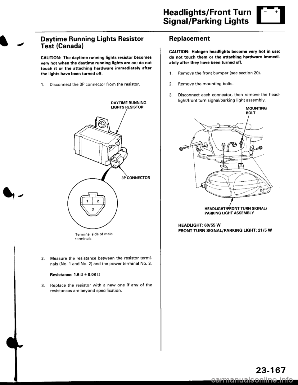
Daytime Running Lights Resistor
Test (Canada)
CAUTION: The daytime running lights resistor becomes
very hot when the daytime running lights are on; do not
touch il or the attaching hardware immediately after
the lights have been iurned off.
1. Disconnect the 3P connector from the resistor.
Terminal side of male
terminals
N4easure the resistance between the resistor termi
nals (No. 1 and No. 2) and the power terminal No. 3.
Resistance: 1.6 O t 0.08 O
Replace the resistor with a new one if any of the
resistances are beyond specification.
It-
Replacement
CAUTION: Halogen headlights b€come very hot in use;
do not touch them or the attaching hardware immedi-
ately after they have been turned off.
1. Remove the front bumper (see section 20).
2. Remove the mounting bolts,
3. Disconnect each connector, then remove the head-
lighVfront turn signal/parking light assembly.
MOUNTINGEOLT
HEADLIGHT/FRONT TUFN SIGNAL/PARKING LIGHT ASSEMBLY
HEADLIGHT: 60/55 W
FRONT TURN SIGNAL/PARKING LIGHT: 21l5 w
23-167
Page 1638 of 2189
Headlights
Adjustment
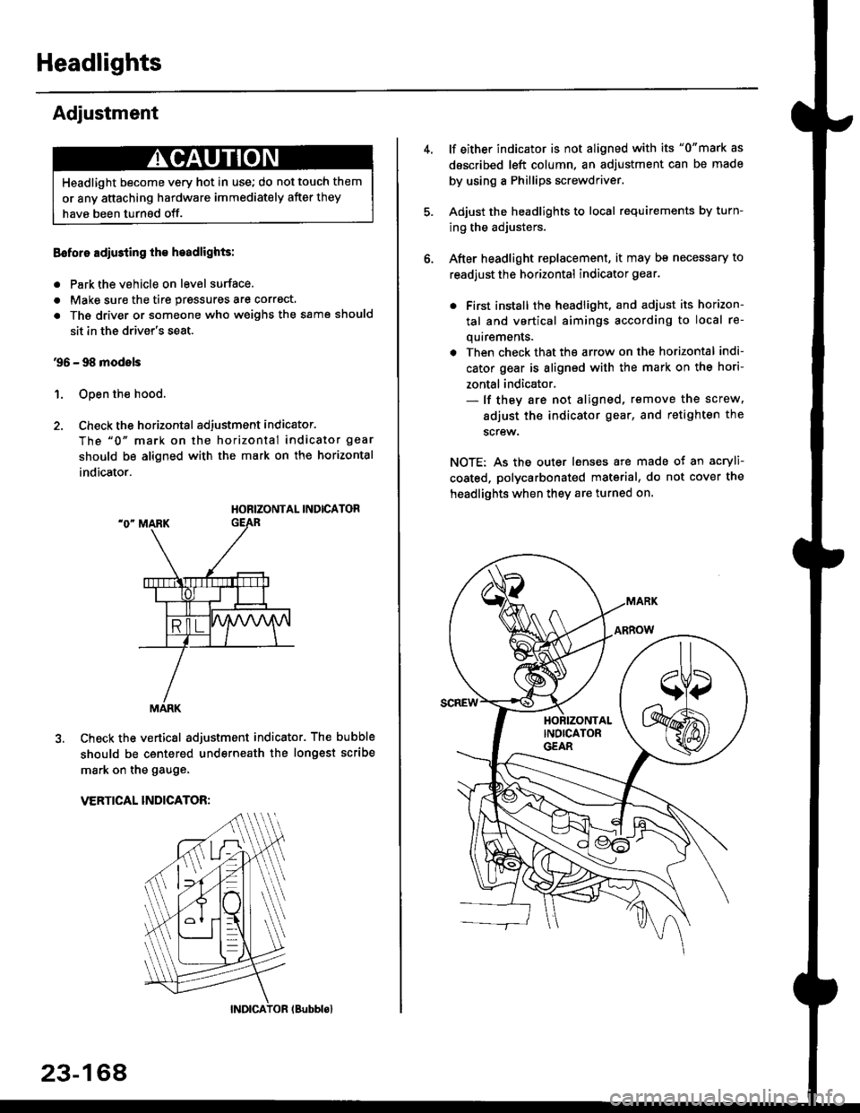
Eoforo adiu3ting th€ h.adlights:
. Park the vehicle on level surface.
. Make sure the tire prgssures are correct.
a The driver or someone who weighs the same should
sit in the driver's seat.
96 - 98 modols
1. Open the hood.
2. Check the horizontal adjustment indicator.
The "0" mark on the horizontal indicator gear
should be aligned with the mark on the horizontal
indicator.
HORIZONTAL INDICATOR
Check the vertical adjustment indicator. The bubble
should be centered underneath the longest scribe
mark on the gauge.
VERTICAL INDICATOR:
Headlight become very hot in use; do not touch them
or any attaching hardware immediately after they
have been turnsd off.
MARK
23-164
(Bubblol
lf either indicator is not aligned with its "0"mark as
described left column, an adjustment can be made
by using a Phillips screwdriver.
Adjust the headlights to local requirements by turn-
ing the adjusters.
After headlight replacement, it may bs necessary to
readjust the horizontal indicator gear.
. First install the headlioht, and adjust its horizon-
tal and vertical aimings according to local re-
quirements.
. Then check that the arrow on the horizontal indi-
cator gear is aligned with the mark on the hori-
zontal indicator.- lf they are not aligned, remove the screw,
adiust the indicator gear, and retighten the
screw.
NOTE: As the outer lenses are made ot an acryli-
coated, polycarbonated material, do not cover the
headlights when they are turned on.