Front end HONDA CIVIC 1996 6.G Repair Manual
[x] Cancel search | Manufacturer: HONDA, Model Year: 1996, Model line: CIVIC, Model: HONDA CIVIC 1996 6.GPages: 2189, PDF Size: 69.39 MB
Page 1767 of 2189
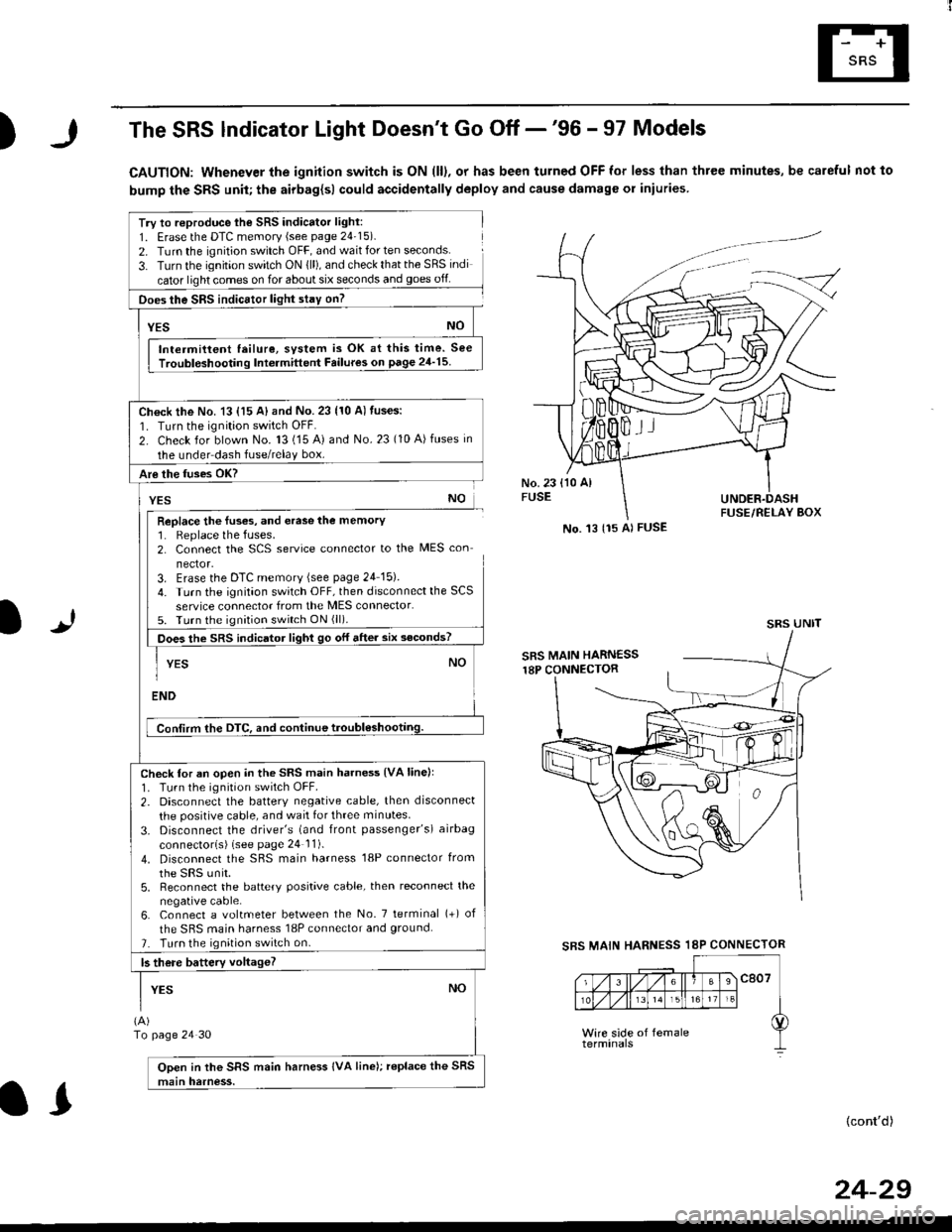
)The SRS lndicator Light Doesn't Go Off -'96 - 97 Models
CAUTION: Whenever the ignition switch is ON (ll), or has been turned OFF for less than three minutes, be careful not to
bump the SRS unit; the airbag{sl could accidentally deploy and cause damage or iniuries
Try to reproduce lhe SRS indicator light:
1. Erase the DTC memory (see page 24'15).
2. Turn the ignition switch OFF, and wait for ten seconds.
3- Turn the ignition switch ON {ll), and check that the SRS indi
cator light comes on for about six seconds and goes off
Does the SRS indicEtor light stay on?
[*NO
Intermittent lailure, system is OK at this time. See
Troubloshooting Int6rmittent Failures on page 24'15
Ch€ck the No. 13 {15 A} and No. 23 (10 A) fuses:
1. Turn the ignition switch OFF.
2. Check for blown No. 13 (15 A) and No.23 (10 A)fuses in
the under dash fuse/relay box.
Are the fuses OK?
vEs No
Replace the luses, and erase the memory1. Replace the fuses.2. Connect the SCS service connector to the MES con
nector.3. Erase the DTC memory (see page 24 15).
4. Turn the ignitaon switch OFF, then disconnect the SCS
service connector from the MES connector.5. Turn the ignition switch ON (ll).
Does the sRS indicato, tigt t go or "ne. "ii--JJl
-I YEs NO1
ENDi
Conlirm the DTC, and continue troubl6shootilg.
Check for an open in the SRS main harness {VA linell'1. Tu.n the ignition switch OFF.
2. Disconnect the battery negative cable, then disconnect
the positive cable, and wait for three minutes.
3. Disconnect the driver's (and front passenger's) airbag
connectorls) (see page 24 11).
4. Disconnect the SBS main harness '18P connector from
the sRS unir.5, Reconnect the battery positive cable, then reconnect the
negative cable.6. Connect a voltmeter between the No. 7 tetminal (+) of
the SRS main harness 18P connector and ground.
7. Turn the ignition switch on.
b there battery voltageT
YESNO
(A)
To page 24 30
Open in the SRS main harness IVA line); replace the SRS
main harness.
l.J
SBS MAIN
(cont'd)
No. 't3 {15 Al FUSE
SRS UNIT
HARNESS 18P CONNECTOR
II
24-29
Page 1777 of 2189
.J
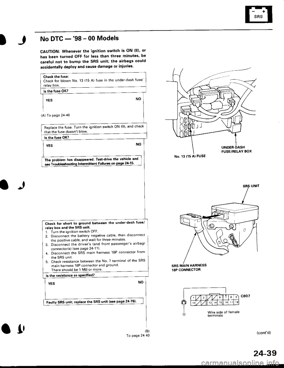
No DTC -'98 - 00 Models
CAUTION: Whenever the ignition switch is ON (ll), or
has been turned OFF for less than three minuies. be
careful not to bump the SRS unil; the airbags could
accidentally deploy and cause damage or iniuries
(A) To page 24'40
Check for short to ground betweon the under-dash fuse/
relav box end the SRS unil
1. TLrrn the ignition switch OFF
2, Disconnect the battery negative cable, then drsconnect
the positive cable, and wait for three minutes'
3. Disconnect the driver's {and front passenger's airbag)
connector{s) {see Page 24_11)
4. Disconnect the SRS main harness 18P connector irom
5. Check resistance between the No 7 terminal of the SRS
main harness 18P connector and ground
There should be 1 M0 or more
(cont'd)
No. 13 {15 A) FUSE
sRs MAIN HARNESS
Check the tuse:Check Ior blown No 13 {15 A) fuse in the under dash fuse/
Beplace the fuse. Turn the ignition switch ON (lll, and check
that lhe tuse doesn't blow
The oroblem has disappeared. Test'drive thc vehicle and
s6e Troubleahoodng lntermittent Failures on pago 2&15
Faufty SRS uniu replace the SRS unii (see page 21-761'
(8)
To page 24 40O1'
24-39
Page 1781 of 2189
)
1J
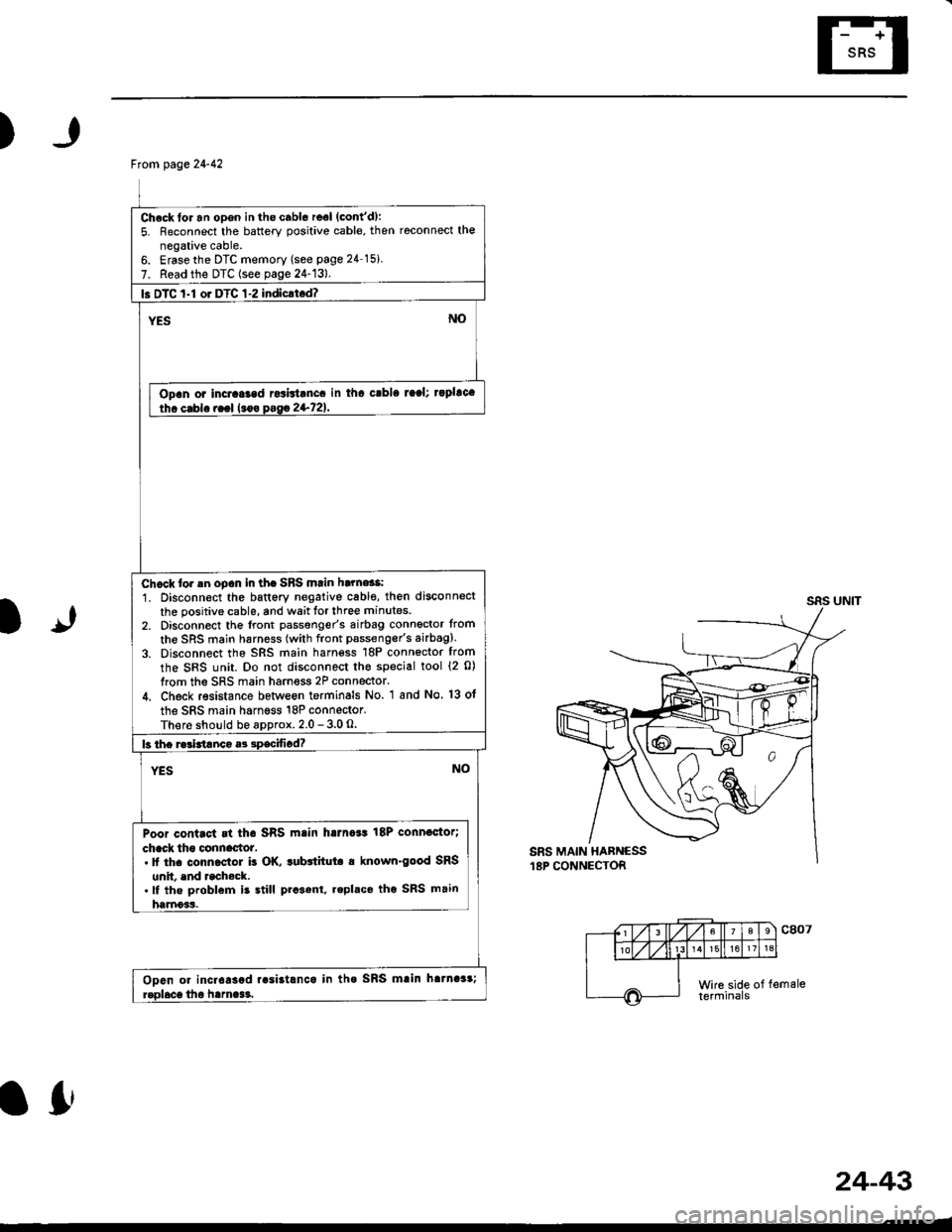
From page 24-42
Check for an opgn in the cabl6 reel (cont'd):
5. Reconnect the battery positive cable, then roconnect the
negative cable.6. Erasethe DTC memory (see page 24 15i
7. Read the DTC (see page 24-13).
l. DTC 1-l or DTC 1-2 indicrt.d?
Opan or incraGad rcsbtanca in tha crbla raal; rapllca
Chcck lor .n oDcn in th. SBS mtin harne$i
1. Disconn€ct the battery negative cabl€, then disconnect
the positive cable, and wait tor three minutes
2, Disconnect the lront passgnger's airbag connoctor from
the SRS main harness (with front pssseng€r's airbag).
3. Disconnect the SRS main harn€ss 18P connector from
the SRS unit. Do not disconnect the special tool {2 0)
from the SRS main harness 2P connector.
4. Check resistance betlveon terminals No. 1 and No 13 ot
the SRS main harness 18P connector.
There should be approx. 2.0 - 3.0 O.
Poor contact rt tha SRS main harna*t 18P connactor;
chack tho clnnactot,. It th. conn.ctol b OK. tubttitut. a known-good SRS
unit. end rcchock..lf the problem is still prcsent, replace tho SRS main
harnoss.
Ooen or incr6asad r.si3tlnca in tha SRS mlin hatnaar;
lfr
24-43
Page 1808 of 2189
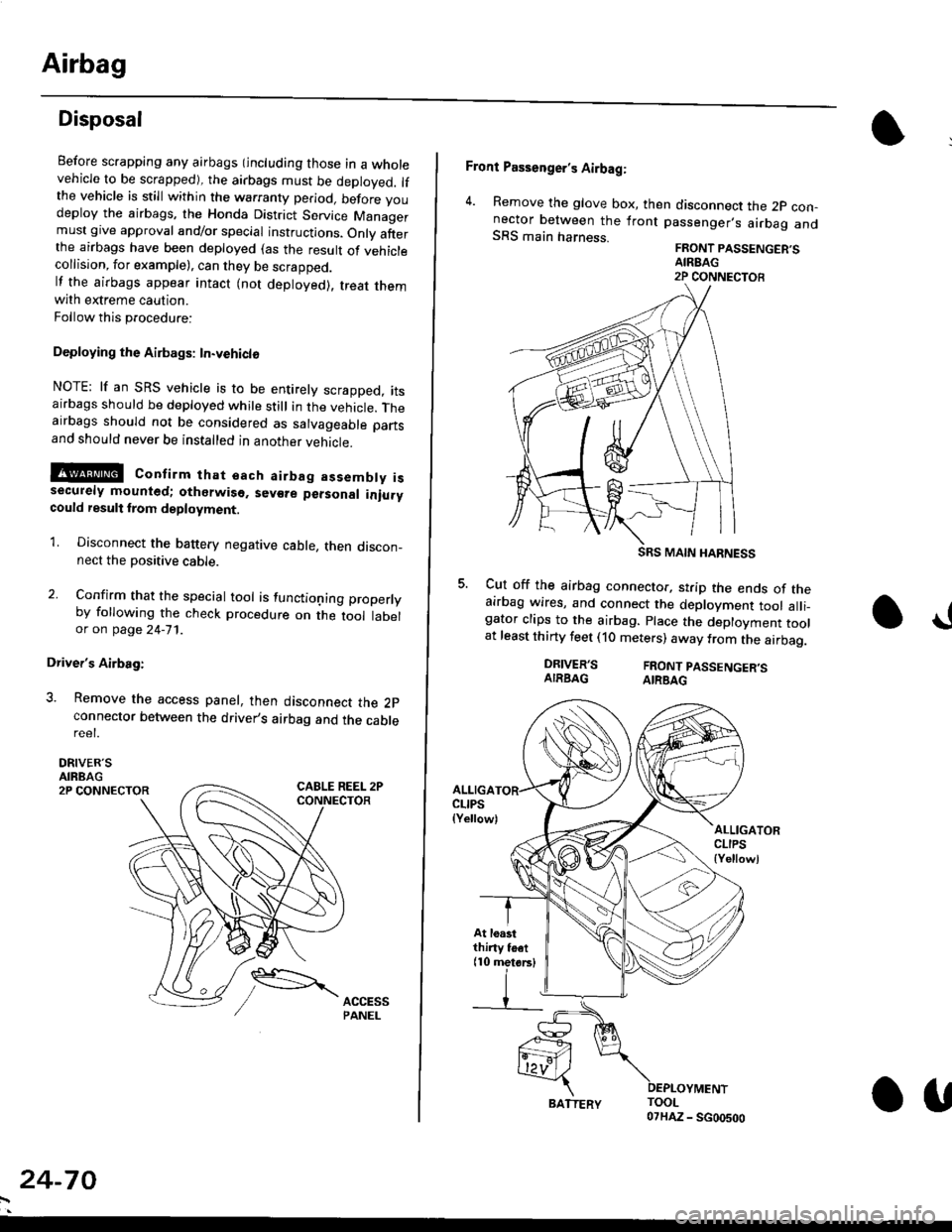
Airbag
Disposal
Before scrapping any airbags (including those in a wholevehicle to be scrapped), the airbags must be deployed. lfthe vehicle is still within the warranty period, before youdeploy the airbags, the Honda District Service Managermust give approval and/or special instructions. Onlv afterthe airbags have been deployed (as the result of vehiclecollision, for example), can they be scrapped.lf the airbags appear intact (not deployed). treat themwith extreme caution.
Follow this p.ocedure:
Deploying the Airbags: In.vehiclo
NOTE: lf an SRS vehicle is to be entirely scrapped, itsairbags should be deployed while still in the vehicle. Theairbags should not be considered as salvageable partsand should never be installed in another veh;cle.
!@ confirm thst oach airbag assembty issecurely mounted; otharwiso. sev€re personal iniurycould result lrom deployment.
1. Disconnect the baftery negative cable, then discon_nect the positive cable.
2. Confirm that the special tool is functioning properlyby following the check procedure on the tool labelor on page 24-'l'l .
Driver's Airbag:
3. Remove the access panel, then disconnect the 2pconnector between the driver,s airbag and the cablereet.
DRIVER'SAIRBAG2P CONNECTOR
24-70
BATTERY.U
Front Passenger's Airbag:
4. Remove the glove box, then disconnect the 2p con-nector between the lront passenger,s airbag andSRS main harness.FRONT PASSENGER'SAIREAG2P CONNECTOB
SRS MAIN HARNESS
Cut off the airbag connector, strip the ends of theairbag wires, and connect the deployment tool alli_gator clips to the airbag. place the deployment toolat least thirty feet (10 meters) away from the airbag.
a!
DRIVER'SAIRBAGFRONT PASSENGER'SAIRBAG
ALLIGACLIPS(Yellow)ALLIGATORCLIPS{Yellowl
At loastthiny toet(10 metorsl
Page 1814 of 2189
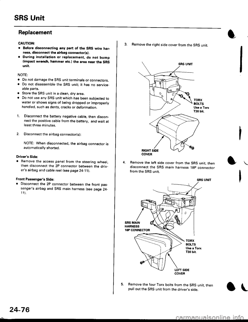
SRS Unit
Replacement
CAUTION:
. Betore disconnoqting lny pErt of the SRS wire hal-ness, disconnect th9 airbag conn"ctorlsl.. During installltion or teplacemsnt. do not bump(impact w.cnch, hamm€r stc.l the area noar tho SRSunit.
NOTE:
o Do not damage the SRS unit terminals or connectors.. Do not disassemble the SRS unit; it has no service-able parts,
. Store the SRS unit in a clean, dry a.ea,. Do not use any SRS unit which has be€n subjected towater or shows signs of being dropped or improperlyhandled. such 8s dents, cracks or deformation.
1. Disconnect the bsttery negative cable. then discon-nect the positive cable from the battery, and wait atleast three minutes.
2. Disconnect the airbag connector{s}:
NOTE: When disconnected, the airbag connector isautomatically shorted,
Driver's Side:
. Remove the access panel from the steering wheel.then disconnect the 2P connector between the driv_er's airbag and cable reel (see page 24-11).
Front Passenge/s Side:. Disconnect the 2P connector between the tront oas_senger's airbag and SRS main harness (see page 24-11).
24-76
o\
3. Remove the right side cover from the SRS unit.
SRS UNTT
TOBXBOLTSUge a TorxT30 bit.
RIGHT SIOE
Remove the left side cover from the SRS unit, thendisconnect the SRS main harness lgp connectorfrom the SBS unit.
SRS UNIT
5. Remove the four Torx bolts from the SRS unit, thenpull out the SRS unit from the driver,s side,
COVER
Page 2106 of 2189

IO151. Lower Front of Transmission (Si)
152. Left Center of End Panel ('99-'00 Sedan)
201-25
Page 2141 of 2189
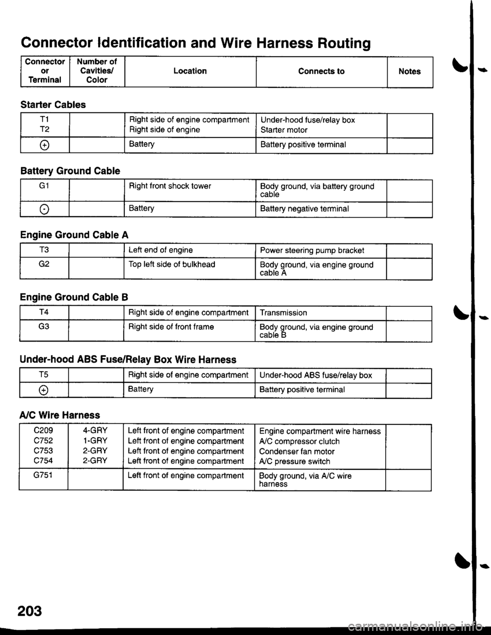
Connector ldentification and Wire Harness Routing
Connector
or
Terminal
Number of
Cavities/
Color
LocationConnects toNotes
Starter Cables
T1
r2
Right side of engine compartment
Right side of engine
Under-hood luse/relay box
Staner motor
t+lBatteryBattery positive terminal
Battery Ground Cable
Right front shock towerBody ground, via battery ground
cable
oBatteryBattery negative terminal
Engine Ground Cable A
t!tLeft end of enginePower steering pump bracket
Too left side ot bulkheadBody ground, via engine ground
cable A
Engine Ground Cable B
T4Bight side of engine compartmentTransmission
(ritRight side of front frameBody ground, via engine ground
Under-hood ABS Fuse/Relay Box Wire Harness
tcRight side of engine compartmentUnder-hood ABS fuse/relay box
oBatteryBattery positive terminal
A,/C Wire Harness
c209
wtJl/,\-7Ee
c754
4-GRY
1.GRY
2-GRY
2-GRY
Lefl front of engine compartment
Left front of engine compartment
Lefl front of engine compartment
Left tront of engine compartment
Engine compartment wire harness
A,/C compressor clutch
Condenser fan motor
A,/C pressure switch
G751Left front of engine compartmentBody ground, via A,/C wireharness
Page 2143 of 2189
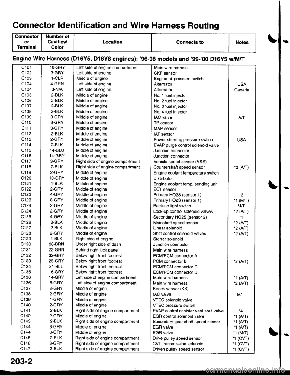
Connector ldentification and Wire Harness Routing
Connector
or
Terminal
Number ot
Cavities/
Golor
LocationConnects toNotes
Engine Wire Harness (Dl6Y5, D16Y8 engines): '96-98 models and '99;00 D16Y5 dM/T
c101
c102
c 103
c104
Q104
c105
c106
c107
cl 08
cl09
cl10
c1l1
cl'12
c113
c114
c'115
c116
c'117
c 118
c119
c120
c121
c122
c123
c123
c124
Q124
c125
c 126
c127
c128
c129
c130
c131
cl32
c 134
c135
c136
c137
c138
c139
c'140
c141
c142
c143
c144
c'|44
c145
c146
c147
1O-GRY
3.GRY
1-CLR
4-GRN
3-N/A
2-BLK
2-BLK
2-BLK
2-BLK
3-GRY
3-GRY
3-GRY
2.BLK
2.GRY
2-BLK
14-BLU
14-GRY
3.GRY
2-BLK
2-GRY
1O-GRY
1.BLK
2.GRY
4-GRY
8-GRY
2-GRY
2.GRY
4-GRY
2.BLK
2.BLK
2-GRY
1.BLK
2O.BRN
22.GRN
32.GRY
25.GRY
31-BLU
16.GRY
14-GRY
8.GRY
2-GFIY
2.GRY
1-GRY
2-GRY
2-BLK
2-GRY
2.BLK
3-GRY
6-GRY
2.BLK
8-GRY
2-BLK
Left side of engine compartment
Left side of engine
Middle of engineI att .i.la ^f an^i^6
Left side ot engine
Middle of engine
Middle of engine
Middle of engine
Middle of engine
Middle of engine
[,liddle of engine
Middle ot engine
Middle ot engine
Middle of engine
Middle of engine
Middle of engine
l\,liddle of engine
Right side of engine compartment
Right side of engine compartment
Middle ot engine
Middle of engine
Middle of engine
Middle of engine
l\,liddle of engine
Nliddle of engine
Middle ot engine
Middle of engine
Middle ot engine
Middle of engine
Middle of engine
Nliddle of engine
Right side of engine
Under right side of dash
Behind right kick panel
Below right front footrest
Below right front footrest
Below right front footrest
Below right front tootrest
Left side ot engine compartment
Left side of engine compartment
Middle of engine
liliddle ot engine
Middle of engine
Nriddle ol engine
Right side of engine compartment
Middle ol engine
Right side of engine compartment
Middle of engine
N,liddle of engine
Right side of engine compartment
Right side of engine compartment
Bight side of engine compartment
Main wire harness
CKF sensor
Engine oil pressure switch
Alternator
Alternator
No. 1 fuel injector
No. 2 fuel injector
No. 3 fuel injector
No.4 fuel injector
IAC valve
TP sensor
MAP sensor
IAT sensor
Power steering pressure switch
EVAP purge control sol€noid valve
Junction connector
Junction connector
Vehicle speed sensor (VSS)
Countershatt speed sensor
Engine coolant temperature switch
Distributor
Engine coolant temp. sending unit
ECT sensor
Primary HO2S (sensor '1)
Primary HO2S (sensor '1)
Back-up light switch
Lock-up control solenoid valves
Secondary HO2S (sensor 2)
lvlainshafl speed sensor
Lanear solenoid
Shift control solenoid valves
Starter solenoid
Junction connector
Main wire harness
ECM/PCM connector A
PCM connector B
ECM/PCNI connector C
ECM/PCl\,,| connector D
Main wire harness
Maln wire harness
Knock sensor (KS)
IAC valve
VTEC solenoid valve
VTEC pressure switch
EVAP control canister vent shut valv€
EGR control solenoid valve
Secondary gear shatt speed sensor
EGR valve
EGR valve
Drive pulley speed sensor
CVT transmission solenoid
Driven pulley speed sensor
USA
Canada
AlT
USA
'2( tr\
'3
-1 (M/r)
t\4/T'2 (Anl'1
'2 (An)'2 (Nr)'2 (AtT)
'2 (Atr)
-1 (An)-2( fi|
M/T
.1 (Arr).1 (A,T)"1 (A/r)-1 (M/r).1 (CVT),1 (cw)'1 (CVT)
203-2
Page 2145 of 2189
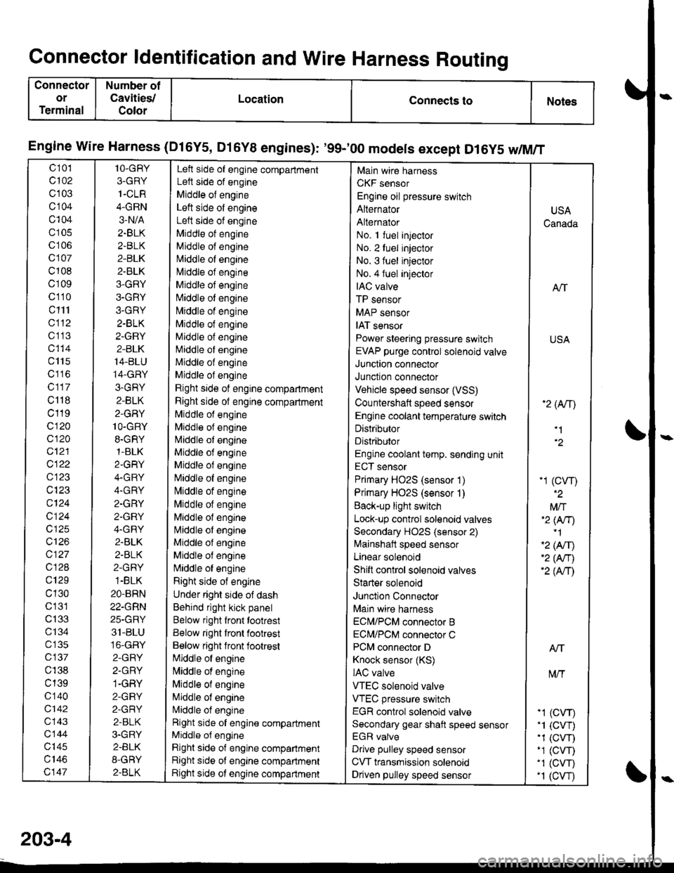
Connector ldentification and Wire Harness Routing
Connector
or
Terminal
Number of
Cavities/
Color
LocationConnects toNotes
Engine wire Harness (Dl6Y5, Dl6Y8 engines): '99-'00 models except D16y5 w/M/T
c 101
c102
c103
cl04
c104
c105
c106
c107
c108
c109
c110
c111
cl12
c1 13
c115
c117
c118
c119
c120
c120
c12'l
cl22
c123
c124
c124
c125
c126
c127
c128
c129
c130
c'131
c133
ct34
c 135
c137
c138
c139
c 140
c142
c143
c144
c'|45
c147
1O-GRY
3.GRY
1-CLR
4-GRN
3-N/A
2.BLK
2.BLK
2-BLK
2.BLK
3-GRY
3-GRY
3.GRY
2-BLK
2.GRY
2-BLK
14-BLU
14-GRY
3-GRY
2-BLK
2-GRY
1O-GRY
8.GRY,1-BLK
2.GRY
4.GRY
4.GRY
2.GRY
2.GRY
4.GRY
2.BLK
2-BLK
2-GRY
1-BLK
2O-BRN
22-GRN
25-GRY
31-BLU
16-GRY
2-GRY
2.GRY
1-GRY
2-GRY
2-GRY
2-BLK
3.GRY
2.BLK
8-GRY
2.BLK
Left side of engine compartment
Left side of engine
Middle of engine
Left side of engine
Left side of engine
Middle ot engine
Middle of engine
N,liddle of engine
l\4iddle of engine
Middle of engine
Niliddle of engine
N,,liddle of engine
Middle of engine
Middle of engine
Middle of engine
Middle of engine
Middle of engine
Rjght side of engine compartment
Right side of engine compartment
Middle of engine
Mlddle of engine
l\4iddle of engine
Middle of engine
Middle of engine
[iliddle of engine
lvliddle of engine
Middle of engine
Middle of engine
l\4iddle of engine
Middle ol engine
Middle of engine
N,liddle of engine
Right side of engine
Under right side of dash
Behind right kick panel
Below right front tootrest
Below right front footrest
Below right lront footrest
[iliddle of engine
l\,liddle of engine
Middle of engine
Middle of engine
L4iddle of engine
Right side of engine compartment
Middle of engine
Right side of engine compartment
Right side of engine compartment
Right side ot engine compartment
Main wire harness
CKF sensor
Engine oil pressure switch
Alternator
Alternator
No. 1 fuel injector
No. 2luel injector
No. 3 fuel injector
No.4 fuel injeclor
IAC valve
TP sensor
MAP sensor
IAT sensor
Power steering pressure switch
EVAP purge control solenoid valve
Junction connector
Junction connector
Vehicle speed sensor (VSS)
Countershaft speed sensor
Engine coolant temperature switch
Distributor
Distributor
Engine coolant temp. sending unit
ECT sensor
Primary HO2S (sensor 1)
Primary HO2S (sensor 1)
Back-up light switch
Lock-up control solenoid valves
Secondary HO2S (sensor 2)
Mainshait speed sensor
Linear solenoid
Shift control solenoid valves
Starter solenoid
Junction Connector
Main wire harness
ECN4/PCM connector B
ECM/PCM connector C
PCM connector D
Knock sensor (KS)
IAC valve
VTEC solenoid valve
VTEC pressure switch
EGR control solenoid valve
Secondary gear shaft speed sensor
EGR valve
Drive pulley speed sensor
CVT transmission solenoid
Driven pulley speed sensor
USA
Canada
ATT
USA
'2 (An\
'1
-1 (cw)
Mft'2 lNr)'1
'2 (Afil'2 (An)'2 (Anl
Atf
t\4/T
-1 (CVr)'1 (CVT).1 (CW)-1 (CVT)'1 (CVT).1 (cw
203-4
Page 2147 of 2189
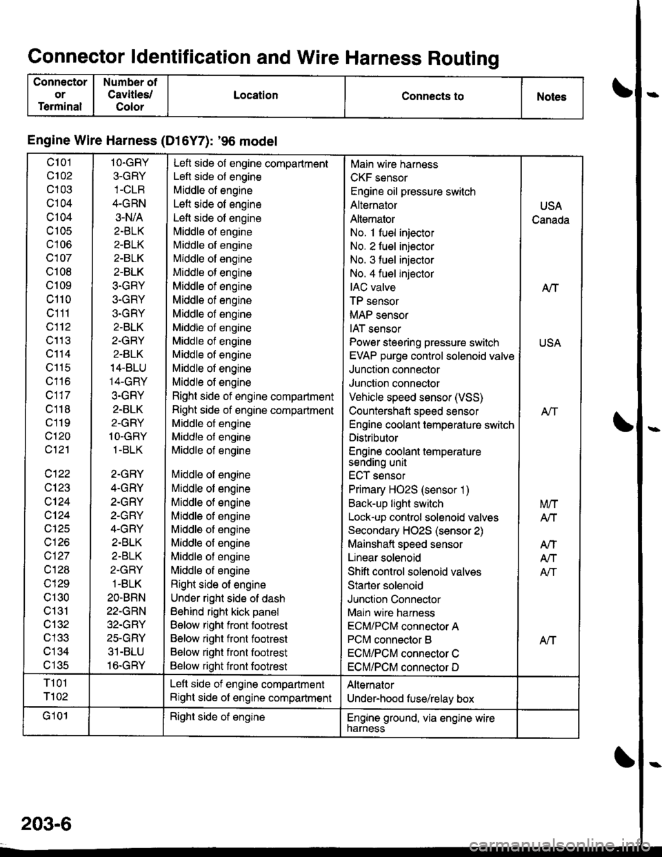
Connector ldentification and Wire Harness Routing
Connector
or
Terminal
Number of
Cavities/
Color
LocationConnects toNotes
Engine Wire Harness (Dl6Y7): '96 model
c101
c102
c103
cl04
c104
c 105
c106
c107
c108
c109
c110
c111
c112
c11 3
c114
c115
c116
c117
c118
c119
c120
c121
c122
c123
c124
cl24
c125
c126
c127
cl28
c129
c130
c131
cl32nl2?
c134al eR
1O.GRY
3-GRY
4.GRN
3-N/A
2.BLK
2-BLK
2-BLK
2-BLK
3.GRY
3-GRY
3.GRY
2-BLK
2.GRY
2-BLK
14-BLU
14-GRY
3.GRY
2.BLK
2-GRY
1O-GRY
1 -BLK
2-GRY
4.GRY
2.GRY
2-GRY
4-GRY
2.BLK
2-BLK
2-GRY
1-BLK
2O-BRN
22-GRN
32.GRY
25-GRY
31-BLU
16.GRY
Left side of engine compartment
Left side of engine
Middle of engine
Left side of engine
Lefl side of engine
Middle of engine
Middle of engine
Middle of engine
Middle of engine
Middle of engine
Middle of engine
Middle of engine
Middle of engine
Middle of engine
Middle of engine
Middle of engine
Middle of engine
Right side of engine compartment
Right side of engine compartment
Middle of engine
Middle of engine
Middle of engine
Middle of engine
Middle of engine
Middle of engine
Middle of engine
Middle of engine
Middle of engine
Middle of engine
Middle of engine
Right side of engine
Under right side of dash
Behind right kick panel
Below right front footrest
Below right front footrest
Below right front footrest
Below right front footrest
Main wire harness
CKF sensor
Engine oil pressure switch
Alternator
Altemator
No. 1 fuel injector
No. 2 fuel injector
No. 3 fuel injector
No. 4 fuel injector
IAC valve
TP sensor
MAP sensor
IAT sensor
Power steering pressure switch
EVAP purge control solenoid valve
Junction connector
Junction connector
Vehicle speed sensor (VSS)
Countershaft speed sensor
Engine coolant temperature switch
Distributor
Engine coolant temperaturesending unit
ECT sensor
Primary HO2S (sensor 1)
Back-up light switch
Lock-up control solenoid valves
Secondary HO2S (sensor 2)
Mainshaft speed sensor
Linear solenoid
Shift control solenoid valves
Starter solenoid
Junction Connector
Main wire harness
ECM/PCM connector A
PCM connector B
ECM/PCM connector C
ECM/PCM connector D
USA
Canada
A/T
USA
Atf
Aff
M/T
Arl
AtT
A/T
Afi
T101
T102
Left side of engine compartment
Right side of engine compartment
Alternator
Under-hood fuse/relay box
G101Right side of englneEngine ground, via engine wirenarness
203-6