16p HONDA CIVIC 1996 6.G Workshop Manual
[x] Cancel search | Manufacturer: HONDA, Model Year: 1996, Model line: CIVIC, Model: HONDA CIVIC 1996 6.GPages: 2189, PDF Size: 69.39 MB
Page 4 of 2189
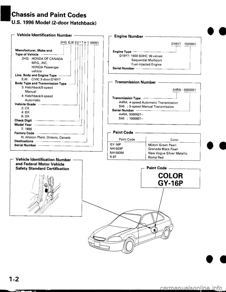
U.S. 1996 Model (2-door Hatchback)
Vehicle ldentif ication Number
2HG EJ6 32*TH I 00001
Manufacturel, Make and
Type of Vehicle
2HG: HONDA OF CANADA
MFG., INC.
HONDA Passenger
vehicle
Line, Body and Engine Type
EJ6: CIVIC 3-door/D16Y7
Body Type and Transmission Type
3: Hatchbaclds-speed
Ma nua I
4: Hatchbacl(4'speed
Automatic
Chassis and Paint Godes
Vehicle Grade
2i CX
4i DX
6: DX
oa
Ch€ck Digit
Model Year
T: 1996
Factory Code
H: Alliston Plant, Ontario, CanadaDestinations
Serial Numbel
Vehicle ldentification Number
and Federal Motor Vehicle
Safety Standard Certif ication
O'
Paint Code
COLOR
GY.l6P
D16Y7 1500001
Engine Type
D 16Y7: 1600 SOHC 16-vatves
Sequential Multiport
Fuel-injected Engine
Serial Number
44RA: 4-speed Automatic Transmission
S40 : s-speed ManualTransmission
GY,16P
NH-503P
NH.583M
R-97
Midori Green Pearl
Granada Black Pearl
New Vogue S jlver lvletallic
Roma Red
1-2
oe
Page 7 of 2189
OO
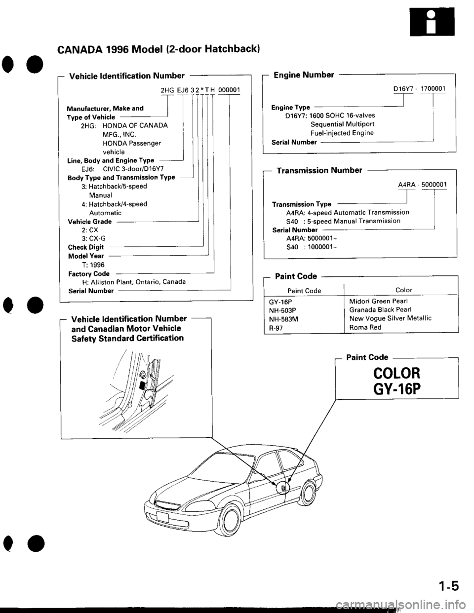
CANADA 1996 Model (2-door Hatchback)
Vehicle ldentification Number
2HG EJ632*TH 000001
Manulacturer, Make and
Type of Vehicle
2HGr HONDA OF CANADA
HONDA Passenger
vehicle
Line, Body and Engino Type
EJ6: ClvlC3-door/D16Y7
Body Type and Transmission TyPe
3: Hatchbacld5-speed
Manua I
4: Hatchbacld4-speed
Automatic
Vehicle Grade
2, Cx
3: CX-G
OO
Check Digit
Model Yeal
T: 1996
Factory Code
H: Alliston Plant, Ontario, Canada
selial Number
Vehicle ldentif ication Number
and Canadian Motor Vehicle
Safety Standard Certification
Paint Code
COLOR
GY.l6P
D 16Y7 -
D16Y7: 1600 SOHC'16-valves
Sequential MultiPort
Fuel-injected Engine
A4RA: 4-sDeed Automatic Transmission
S40 : 5-sDeed Manual Transmission
Midori Green Pearl
Granada Black Pearl
New Vogue Silver Metallic
Roma Red
GY-16P
NH-503P
NH-583M
R-97
00
1-5
Page 257 of 2189
lllustrated Index
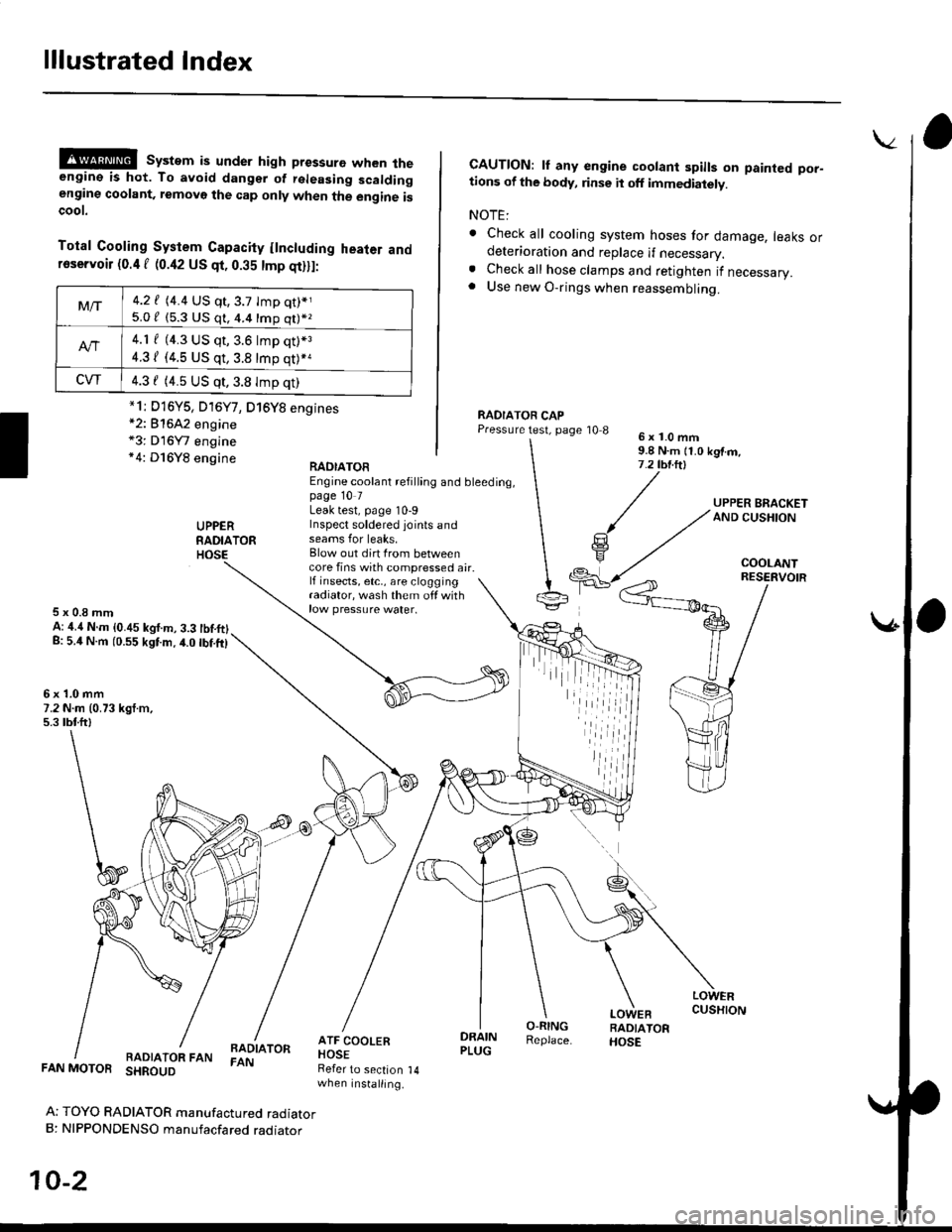
@@ system is under high pressure when theengine is hot. To avoid dangsr of rsleasing scaldingengine coolant, removo the cap only when the engine iscoot.
Total Cooling System Capacity flncluding heater andfoservoir (0.4 f (0.42 US qt, 0.35 tmp qt)ll:
*2: 81642 engine*3: D16Y7 engine*4: D16Y8 engine
CAUTION: lf any engine coolant spills on painted por-tions of the body, rinse it off immediately.
NOTE:
. Check all cooling system hoses for damage, leaks ordeterioration and replace if necessary.. Check all hose clamps and retighten if necessary.. Use new O-rings when reassembling.
RADIATOR CAPPressure test, page '10 86x1.0mm9.8 N.m {1.0 kgtm,7.2 tbt.ltl
UPPERRADIATORHOSE
UPPER BRACKETAND CUSHION
COOLANT
RAOIATOREngine coolant refilling and bleeding,page 10 7Leak test, page 10-9Inspect soldered joints andseams for leaks,Blow out dirt Irom betweencore fins with compressed air.lf insects, etc,, are cloggingradiator, wash them off withrow pressure water.
RESERVOIR
5x0.8mmA: ,1.4 N.m {0.45 kgf.m, 3.3 tbtftlg: 5.4 N.m (0.55 kgtm.4.0 tbf.ft)
6x1.0mm7.2 N.m (0.73 kgt.m,5.3 tbtftl
LOWERCUSHION
RADIATOR FANBADIATORFAN
DRAINPLUG
O-RINGReplace.
LOWEBRADIATORHOSE
FAN MOTOR SHROUD
Ar TOYO RADIATOR manufactured radiatorB: NIPPONDENSO manufacfared raoraror
10-2
Refer to section 14when installing.
Mt-|-4.2 f (4.4 US qt,3.7 tmp qt)*j
5.0 / (5.3 U$ q1, 4.4 16p q11*z
4.1 f (4.3 US qt, 3.6 lmp q0*3
4.31 (4.5 US qt, 3.8 tmp qt)*a
CVT4.3 f (4.5 US qt,3.8 Imp qt)
*1i D16Y5, D16Y7, D16Y8 engines
iil
Page 299 of 2189
System Description
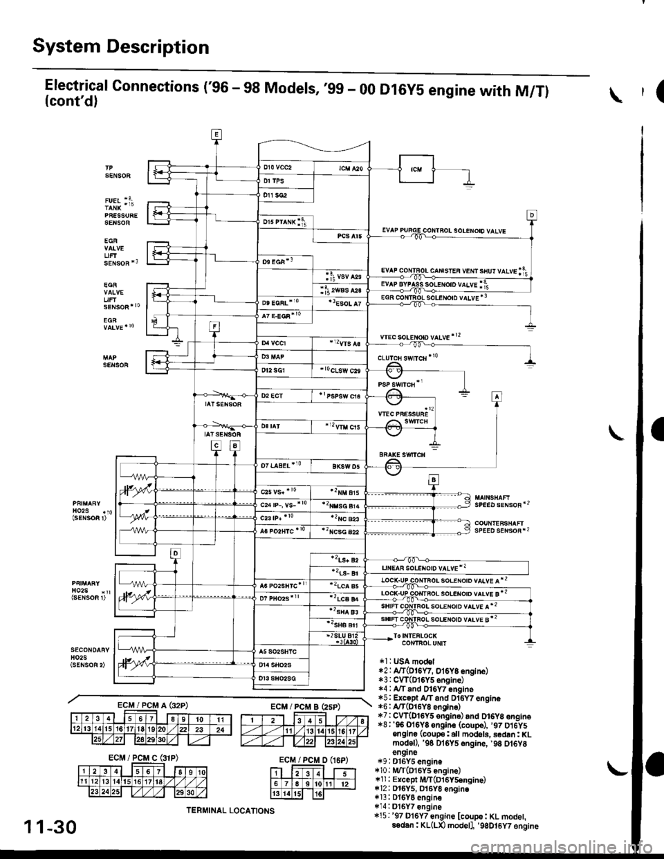
Electrical Connections ('96 - 98 Models, ,99 - 00(cont'd)
PRESSURESENSOE
EGR
UFTsENsoR *3
EGR
uF
D16Y5 engine with M/Tl(
SENSOF
solENoto vALvE *3
wec soLeton vltve'!2
SENSOR
SPEED sENsoR'2
COUNTEFSHAFIsPEED sENsoR*2
soeeloto vltve l*2
ToI|{TEFLOCKCONTBOLUNIT
*l: t SA model*2: A/T(DI6W, oi6y8 engine)*3:CVT(DI6Y5 6ngine)1.4 : A"/T and Dl6Y7 engine*5; Except A/T and Dl6Y7 engine*6: A/T(O16YO engin6)*7:CW(DI6y5 ongine) and D16y8 engino*8;'96 Ol6Y8 sngine (coupe), ,97 D16y5ongine (coup€: all modol!, sedan: KLmodoD, '98 Dl6Y5 engine, '98 ot6Y8en9ne*9:D16Y5 engin.*10 : |!UT(D16Y5 engine)*ll : Except iUT(Dl6Y5engine)*12: D16y5, 016yo engino*13: DI6YO engine*14:Dl6Y7 engine*15:'97 D16Y7 engine [coupe: KL modet,ssdan: KL(LX) modetl, '9gDt6y7 engine
c-rrusren vem srur vtvrlf;
ECM/PCMA(32P)ECM/PCi/lBEsP)
ECM/PCMD(16P)
1 1-30
TERMINAL LOCATIONS
Page 309 of 2189
System Description
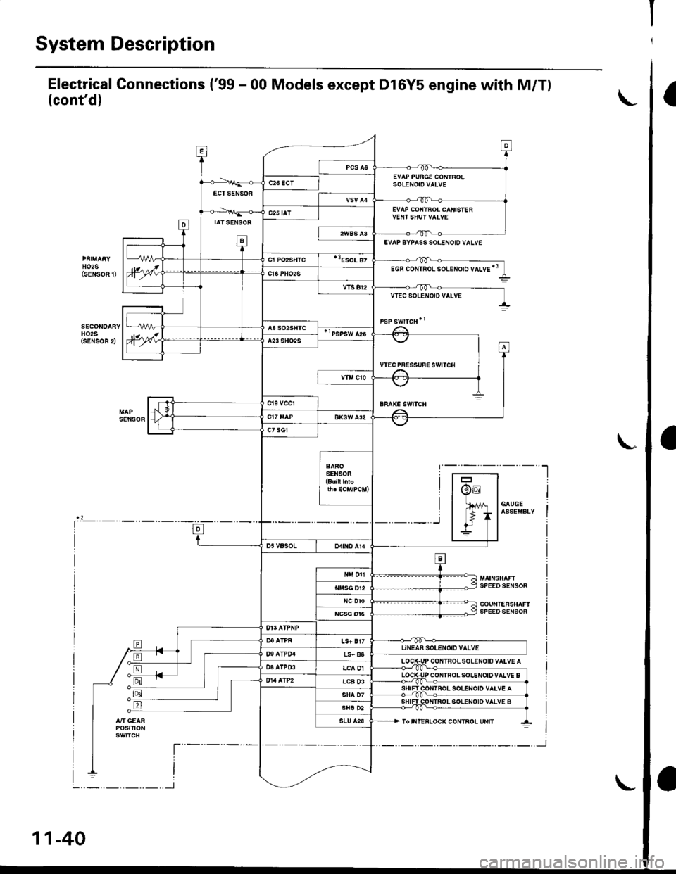
Electrical Connections ('99 - 00 Models except Dl6Y5 engine with M/Tl
(cont'd)
T:I
1
0
EVAP PURGE CONTROLSoLENOtOVAIVEc26 ECTECTSENSOR
D
EVAP COI{TROL CANISIE R
IATSENSOR
ta-t
c25 tAT
HO2S(sENSoFt
EVAP BYPASS SOI.ENOID VALVE
cl Po2s{tc"Eso! 87
)wEGF coNTRoL solENoro vaLvE'"c16PHO2S
vlsBr2VTEC SOLEr{O|D VATVE
H02SiSENSOR 2),wA23 SHO2S
VTECPFESSUFESWITCH
sEt{soR
-t,.1 f
I
BRAKE SWITCH
c7 sG1
SENSOB(Buln l oF
@E
lfil
*_r
/V | GAUGE
* lassEMBLIIl-
SPEEOSENSOR
tr
D5VBSOLo4tND A14
N DTI
NC DTOSPEEDSENSOR
LS+ Bl7UNEAR SOLENOID VALVET'I AT?04LS- a3
LOCIPr. l03alP03LCA 01P CONTBOISOIENOiDVALVE BLCB 03IOI{IROL SOLENOID VAIV€ A
SHIFI COTITROL SOLENOID VALVE BSHE D2
POStTtON
t----
I
To IIIT!FLOCK CONTROL UNIT
--t
L
l-
I
I
11-40
-.._.._.._.._l
,'-J
Page 350 of 2189
Troubleshooting
Troubleshooting Procedures
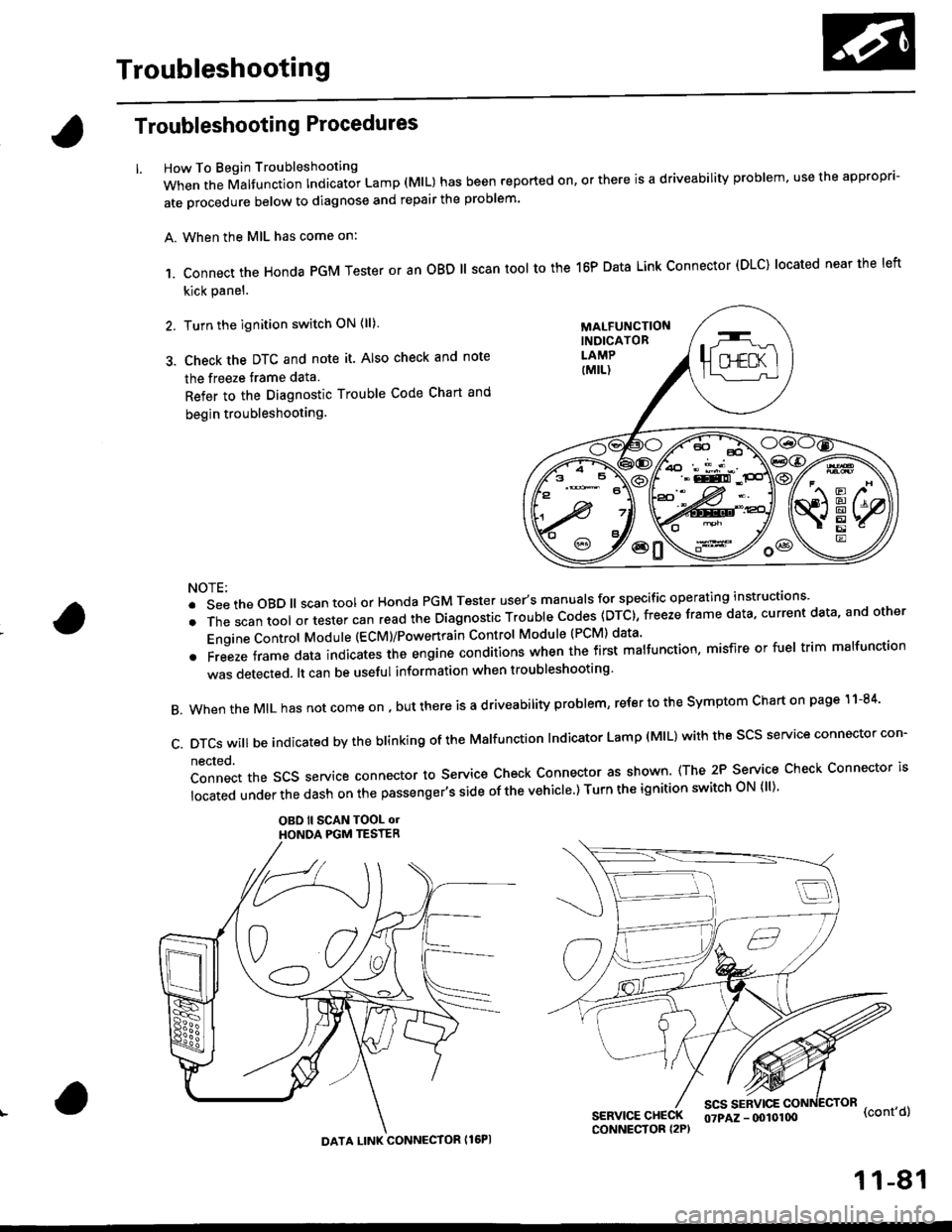
How To Begin Troubleshooting
When the Malfunction Indicator Lamp (MlL) has been reported on, or there is a driveability problem, use the appropr'-
ate orocedure below to diagnose and repair the problem'
A. When the MIL has come on:
,1. connect the Honda PGM Tester or an oBD ll scan tool to the 16P Data Link connector (DLC) located near the left
kick panel.
2. Turn the ignition switch ON (ll)
3. Check the DTC and note it. Also check and note
the freeze trame data
Refer to the Diagnostic Trouble Code Chart and
begin troubleshooting.
NOTE:
.SeetheoBD||scantoolorHondaPGMTesteruser,smanua|sforspecificoperatinginstructions..
.Thescantoo|oltestercanreadtheDiagnosticTroub|ecodes(DTc},freezeframedata,currentdata,andother
Engine Control Module (ECM)/Powertrain Control Module (PCM) data'
oFreezeframedataindicatestheengineconditionswhenthefirstma|function,misfireorfue|trimma|function
was detected. lt can be useful information when troubleshooting'
B. When the MIL has not come on , out there is a d riveability problem, refer to the Symptom Chart on page 1 1-84'
c.DTcswi|lbeindicatedbytheb|inkingoftheMa|function|ndicatorLamp(M|L)withthescsserviceconnectorcon.
nected.
Connect the SCS service connector to Service Check Connector as shown (The 2P Service Check Connector is
|ocatedunderthedashonthepassenger,ssideofthevehic|e')TurntheignitionswitchoN{||)'
OBO ll SCAN TOOL olHONOA PGM TESTER
SERVICE CHECKCONNECTOR I2P)
scs sERvlcE(cont'd)
MALFUNCTIONINDICATORLAMP
DATA LINK CONNECTOR Il6PI
07PAZ - (x)l0100
11-81
Page 360 of 2189
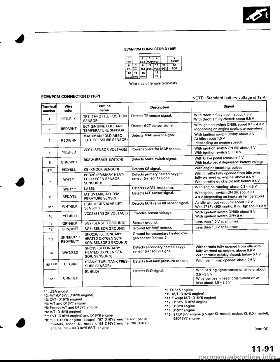
ECM/PCM CONNECTOR D I16P)
Wire side ot female terminals
ECM/PCM CONNECTOR D l16P)NOTE: Standard battery voltage is 12 V
Te.minalnumb€r
Wirecolor
Terminaln!meDor.riptionSignal
RED/BLKTPS (THROTTLE POSITION
SENSOR}
Detects TP sensor signal.With throttle fully open: about 4.8 V
With throttle fully closedl about 0.5 V
REDA/VHTECT {ENGINE COOLANTTEMPERATURE SENSORDetects ECT sensor signalWith ignition switch ON{ll): about 0.1 - 4 8 v
(depending on engine coolant lempe ratu re)
3RED/G RNMAP {MANIFOLD ABSO'LUTE PRESSURE SENSOR}Detects MAP sensor signal.With ignition switch ON(ll): about 3 V
At idle: about 1.0 V
{depending on engine speed)
YEUREDVCCl (SENSOR VOLTAGE)Power source lor MAP sensor.With ignition switch ON (ll): about 5 v
With ignition switch OFF: 0 V
5GRNMHTBKSW {BRAKE SWITCHIDetects brake switch signalWith brake pedal released: 0 v
With brake pedal depressed: baftery voltage
6*?RED/BLUKS {KNOCK SENSOR}Detects KS signal.With engine knocking: Pulses
1
PHO2S (PRIMARY HEAT-ED OXYGEN SENSOR,SENSOR 1)
Detects Primary heated oxygen
sensor (sensor 1l signal
With throttle fullv opened from idle with
Iully warmod up engine: above 0.6 V
With throttle quickly closed: below 0.4 v
LABELDetects LABEL resistanceWith engine r!nning:about 0.3 - 4.9 V
8RED//ELIAT (INTAKE AIR TEM-PERATURE SENSOR)
Detects IAT sensor signal.With ignition switch ON (ll): about 0 1 -
4.8 V {depending on intake air temperature)
9*lWHT/BLKEGRL iEGR VALVE LIFT
SENSOR)
Detects EGR valve lift sensor signalAt idle without vacuum: about'1 2 V
With 27 kPa (2OO mmHg,8 in. Hg): about 4 3 V
10YEUBLUVCC2 (SENSOR VOLTAGE)Provides sensor voltage,With ignition switch ON(ll): about 5 V
With ignition switch OFF:0 V
11GRN/BLKSG2 (SENSOR GROUND}Sensor ground.Less than 1.0 V at alltimes
12G RN,4/1r'HTSG1 (SENSOR GROUND)Ground for MAP sensor.Less than 1.0 V at alltimes
GRN/BLK*1?SHO25G (SECONDARY
HEATED OXYGEN SEN'
SOR, SENSOR 2 GROUND)
Ground for secondary heated oxy-
gen sensor (sensor 2).
14WHT/REDSH02S (SECONDARY
HEATED OXYGEN SEN'soR, sENsoR 2)
Detects secondary heated oxygen
sensor (sensor 2) signal.With throftle fully opened lrom idle with
fully warmed up engine: above 0.6 V
With throttle quickly closed: below 0.4 V
15|3. *15LT GRNPTANK {FUEL TANK PRES.
SURE SENSOR)
Detects fueltank prgssure sensor'With fuelfill caD opened: about 2.5 V
16*1GRN/RED
EL (ELD)Detects ELD signal.With parking lights turned on at idle: about
2.5 - 3.5 VWith low beam headlights turned on at
idle: about 1.5 - 2.5 V
*1: USA model*2r A/T (D16Y7, D16Y8 engine)*3: CVT (D16Y5 engane)*4: A,/T and Dl6Y7 engine*5: Except A/T and D16Y7 engine*6: A"/T (D16Y8 engine)i7: CVT (Dl6Y5 engine) and Dl6Y8 engine*8: .96 D16Y8 engine (coupei,'97 D16Y8 engine
models, sedanr KL model),'98 016Y5 engine,
engine, '99 - 00 D16Y5 (M/T) engine
*9: D16Y5 engine*10: M/T (D16Y5 engine)*11: Except M/T (Dl6Y5 engine)* 12r D16Y5. D16YB engine*13: D16Y8 engine*14: Dl6W engine*15: '97 D16Y7 engine (coupe: KL model, sedan: KL lLX) model),'98D16Y7 engine:(coupe: all'98 D16Y8
(cont'd)
1 1-91
Page 363 of 2189
Troubleshooting
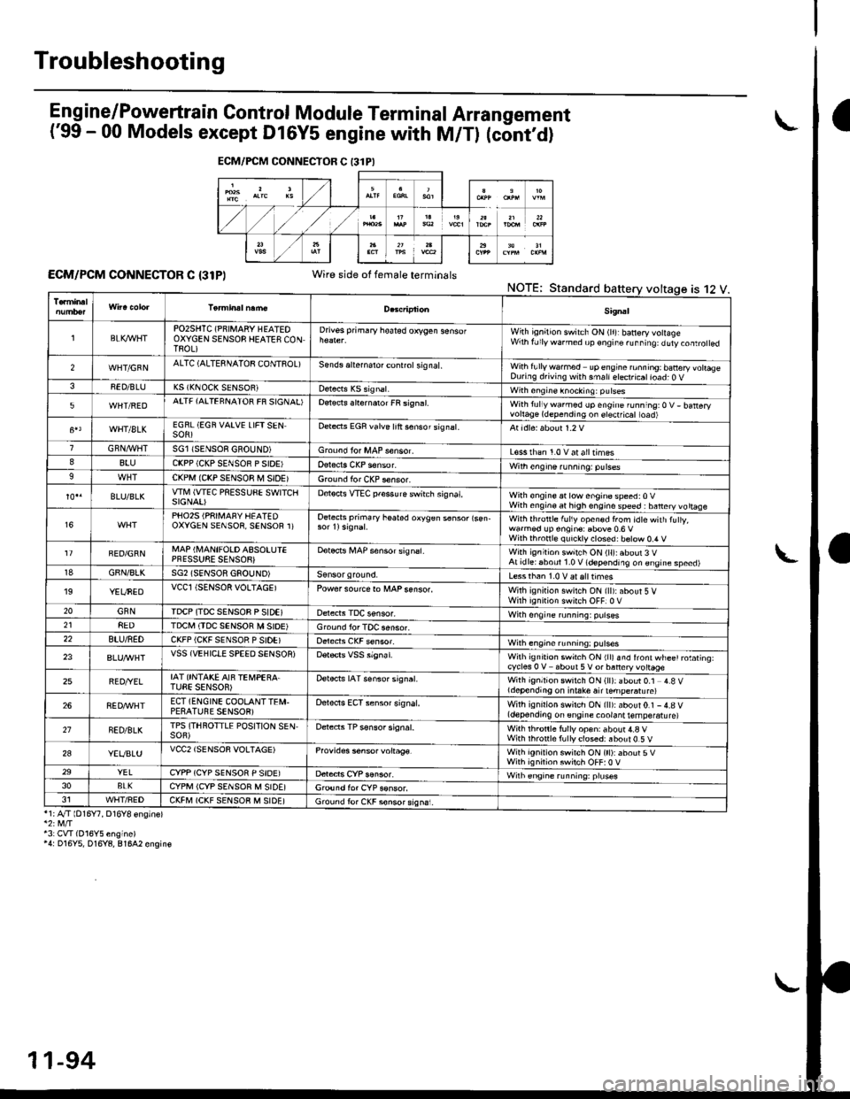
Eng ine/P_owertrain Control Module Term inal Arrangement
('99 - 00 Models except Dl6Y5 engine with M/Tl (cont,d)
ECM/PCM CONNECTOR C {31P)Wire side of female terminalsNOTE;Standard
*1;4"/T lD16Y7, D16Y8 ensinel
43: CVI(016Y5 engine)'4: D16Y5, D16Y8, 81642 engin€
ECM/FCM CONNECTOR C 13lPI
is 12 V.
Sig.al
lBLK4/VHTPO2SHTC (PNIMARY HEATEOOXYGEN SENSOB HEATES CONTROL)
Drivss primary hoated orygen sensofWith ignition switch ON (lr)rbanery volageWrh fJly warned up €ngir. ru..i19: duty.oaro ed
2WHT/GFNALTC (ALTESNATOB CONTSOL)Sends aliernalo. control sig nal,With fullywa.med upengine ronning; banery vohaseDuring d.iving with smallelect.icatioad; O V38ED/BLUK5 (KNOCK SENSOR)with sngine knocking: pulses
5WHT/REDATTF {AITEFNATOR FR SIGNAL'Detects slternaror FR si9n.l.With tullywarmed up engine running:O V- batteryvortage(dependingon erectficat toad)
WHT/8LKEGRL (EGN VAIVE LIFTSENSOR)Dete.ts EGR valve lrft sensorsignat.
GRN,4r'l/flTSGl ISENSOE GBOUND)Groond fo. MAP s€nsor.L€ss rhan 1.0 v at alltimes88luCKPP (CKP SENSOR P SIOE'With engine running: pulses9CKPM {CKP SENSOR M SIDEIGround for CKP sensor.
BLU/BLKwlvl (wEc PREssuSE swtTcllSIGNAI)D€tocts VTEC pfessure switch signat,With €ngine at low enginospeed:0VWith engin€ at high engino speed : banery vo ttaae
16PHO25 (PRII\,1AFY HEATEDOXYGEN SENSOR, SENSOR 1)Oetects primary heated oxygen s6nsor lsen-With lhrottle f!l1y open€d from idtewith tuly,wa.med !p engin€: Ebove 0.6 VWilh thronl€ quickly closed: b€tow 0.4 V
FED/GRNMAP (I\,4ANIFOLD ASSOLUIEPFESSUSE SENSOB}Dotocrs i,4AP sensor signsl.With ignitioh switch ON (ll):about 3 VAt idlei6boul 1.0 V (depending on engine speed)18GBN/8LKSG2 (SENSOR GSOUND)Less than 1.0 V aralttimes'19YEUNEDVCCl (SENSOR VOLTAGEIPowersourcero MAPsenso..With ignition swilch ON {ll):about 5 VWirh iqnition switch OFF]0 V20GNNIDCP (TDC SENSOB P SIDEIWith ongine running: pulses218EDTDCI\,I (TDC SENSOR M SIOE)Ground lor TOC aensor.22BTU/NEDCKFP (CKF SENSOR P SIDE)With engine running: p!lses
23VSS {VEHIClE SPEED SENSOR)Wilh ignrt|on swich ON rllr snd lront wl-ee' rotating.cycles 0 V about 5V or baneryvottage
25BED/YELIAT ONTAKE AIF TEi,4PEBA.TUEE SENSOR)Detects IAT senso. signat.With ignition switch ON (ll): about 0.1 4.8 Vldepending on i.take air ternpe.atu re)
268ED,ryVHTECT (ENGINE COOLANTTEI\,I.PESATUBE SENSOR)Oelects ECT sensor signal.With ignirion swirch ON {ll):about0.1 -4.8 V(depending on engine coolant temperatu re)
21NED/BLKTPS (THROTTLE POSITION SEN,SOF)Detects TP sensor signal.Wilh th.onle fully op€n: about 4.a VWith rhronle f!lly closed: about 0.5 V
2aYEVBLUVCC2 (SENSOR VOLTAGE)Provides s6nsor voltag€.With ignirion swirch ON (tt):about 5VWith ignilion swiich OFF:0 V29YELCYPP (CYP SENSOR P SIDE)Wilh €ngrne running: pruses3oBLKCYPM (CYP SENSOR M SIDE]G,ound for CYP sonsor.J1WHT/FEDCKFM (CKF SENSOB M SIDE)Ground fo. CKF sonsorsign6i.
11-94
Page 364 of 2189
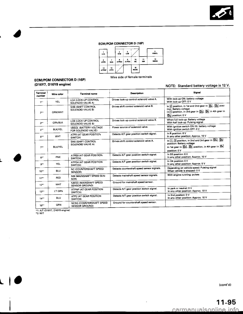
ECM/PCM CONNECTOR O {16P)
Wire side ol temale terminalsECM/PCM CONNECTOR D {16P)
(D16Y7, D16Y8 enginelNOTE: Standard battery voltage is 12 V.
L
.1 A/J (Dl6Y7, Dr6Y8 engine)
(cont'd)
1 1-95
5i!ml
YELLCA (LOCK.UPCON]ROLSOLENOID VALVE A)Orivos look-up controlsol€noid wlv€ a.With lock-up ON: httery vollageWith lock-up OFFi 0 V
GRN,M/HT
SHB {SHIFT CONTFOLSOLENOIO VALVE B)Drivos sh ift cont.ol solanoid valv6 Bln E posnion, in 1st lnd 2nd eoat ,n E E pos'tion:Battsry voltagoInElposirion. in 3rd seat in pd, El in.th sear in
l_�d polition: o v
3''GRN/BLKLC8 (IOCK UP CONTBOLSOLENOID VALVE B)Drivs locl up conttol sol€noid v6lv€ Bwhen fulllock-up: Banory vollagaWnh naf locl-uP: Pulsing si9n6l
5',BLK/YELVSSOI (BATTEsYVOLTAGEFOB SOLENOID VALVE)Powe. sourc€ ol solGnoid valvewirh ignirion sitch ON (ll): battory voltaoeWirh ignnion switch OFF:0 v
ATPR (AT GEAR POSITIONswrTcH)Detecrs Ay'T g6a. position switch signal.In any olh€r position: APProx. 10 V
8LU/YEL
SHA iSHIFI CONTROLSOLENOIDVALVE A)Oriv€6 sh ift conirol sol€noid valve A.ln tr,tr position, in 2nd €nd 3rd sear in lpd, &lposirion: Batt€ry vollsgo;n 1d soar in E, E position, in.ih se6r in E
PNKATPO3 (AT GEAR POSITIONSWITCH)Oot6cts Ay'T S6.r poeirioo switch siSnalIn Enyoth.r position: APPror, t0 v
9''YELATPD4 {AT GEAE POSITIONswrTcH)Oorocts A/I gs8r position switch signal.In any oth6t position:APProx 5 V
BIUNC (COUNTE RSHAFT SPEEDSENSOB)DetocB counr€.shaft sp66d $osr sig.alsD€p€nding on v6hicls 8pe€d;Pul.ins signalWh6n v€hicls i5 ltoPPsd:0 v
REONM (MAINSHAFTSPEED SEN.soR)O€l€cts mainshalt sp€€d 3.nsor 3ign.lsWi$ engino rLrnningl PUls6s
NMSG {MAINSHAFT SPEEOSENSOR GFOUNO)Groundfo, mainshaft sp@d sensor.
13''!T GFNATPNP {AT GEAF POSITIONswrrcH)oetscts A/T 96ar pGitaon swhch signalIn par* or n6ulral:0 VIn sny olhd po3ition: APProx l0V
BLUATPz {AT GEAE POSITIONswrTcHlDor€cis !y'T gos. posilion swilch signal.In any oth6r Position: APProx, 10 V
16''GANNCSG {COUNTEBSHAFT SPEEDSENSOE GROUND)Ground lor countershaii sp€3d s6nsor.
r lo
Page 365 of 2189
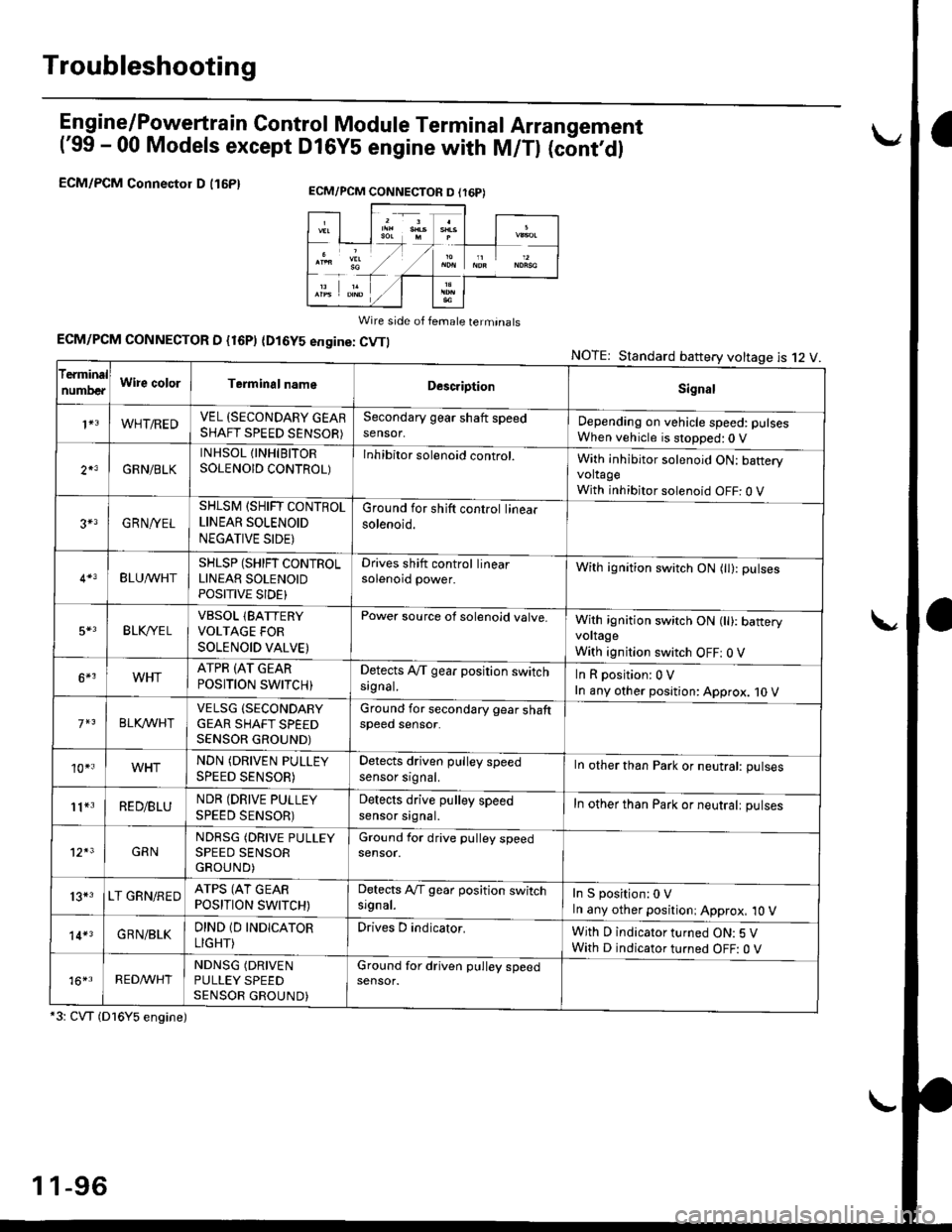
Troubleshooting
En gine/P_oweft ra in Control Module Termina I Arran gement
('99 - 00 Models except Dl6YS engine with M/Tl (cont,dl
ECM/PCM Connectol D (16P1
Wire side of female terminats
ECM/PCM CONNECTOR D {16P) (Dl6YS engine: CVTI
*3: CVT (Dl6Y5 engine)
NOTE: Standard battery voltage is 12 V
ECM/PCM CONNECTON D (r6P)
f€rminal
numDeaWire colorTerminalnameDescriptionSignal
1+3WHT/REDVEL (SECONDARY GEARSHAFT SPEED SENSOR)
Secondary gear shaft speedsensor,Depending on vehicle speed: pulsesWhen vehicle is stopped:0 V
2*3GRN/BLK
INHSOL {INHIBITORSOLENOID CONTROL)Inhibitor solenoid control.With inhibitor solenoid ON: bafteryvoltageWith inhibitor solenoid OFF: 0 V
3+3GRN/YEL
SHLSM (SHIFT CONTROLLINEAR SOLENOID
NEGATIVE SIDE)
Ground for shift control linearsolenoid.
BLU^/vHTSHLSP (SHIFT CONTROLLINEAR SOLENOIDPOSITIVE SIDE}
Drives shift control linearsolenoid power.With ignition switch ON (tl): pulses
5*3BLK,/YE LVBSOL lBATTERYVOLTAGE FOR
SOLENOID VALVE)
Power source of solenoid valve.With ignition switch ON (ll): baneryvoltage
With ignition switch OFF: 0 V
6*3WHTATPR (AT GEAR
POSITION SWITCH)Detects A,/T gear position switchsrgnal.InRposition:0V
In any other position: Approx. 10 V
BLKA/VHIVELSG (SECONDARY
GEAR SHAFT SPEEDSENSOR GROUND)
Ground for secondary gear shaftspeed sensor.
10*.WHTNDN (DRIVEN PULLEY
SPEED SENSOR)
Detects driven pulley speedsensor srgnal.In other than Park or neutral: pulses
11*3RED/BLUNDR (DRIVE PULLEY
SPEED SENSOR)
Detects drive pulley speedsensor srgnal.In other than Park or neutralt pulses
12*3GRNNDRSG (DRIVE PULLEYSPEED SENSORGROUND)
Ground for drive pulley speedsensor.
13*3LT GRN/REDATPS (AT GEARPOSITION SWITCH)
Detects Ay'T gear position switchsrgnal.In S position:0 VIn any other positioni Approx, 10 V
14*3GRN/BLKDIND 1D INDICATOR
LIGHT)
Drives D indicator.With D indicator turned ON: 5 VWith D indicator turned OFF: O V
16*rRED^/VHTNDNSG (DRIVEN
PULLEY SPEEDSENSOR GROUND)
Ground for driven pulley speedsensor.
1 1-96