Throttle position sensor HONDA CIVIC 1996 6.G Workshop Manual
[x] Cancel search | Manufacturer: HONDA, Model Year: 1996, Model line: CIVIC, Model: HONDA CIVIC 1996 6.GPages: 2189, PDF Size: 69.39 MB
Page 140 of 2189
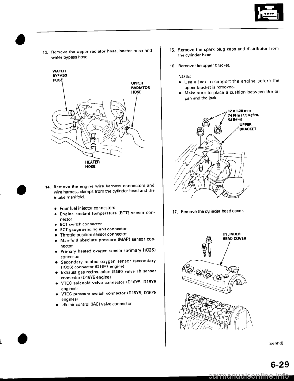
13. Remove the upper radiator hose' heater hose and
water bYPass hose
WATEREYPASSHOSEUPPERRADIATORHOSE
14.
HEATERHOSE
Remove the engine wire harness connectors and
wire harness clamps from the cylinder head and the
intake manifold.
o Four fuel injector connectors
. Engine coolant temperature (ECT) sensor con-
nector
a
a
a
ECT switch connector
ECT gauge sending unit connector
Throttle position sensor connector
Manitold absolute pressure (MAP) sensor con-
nector
Primary heated oxygen sensor (primary HO2S)
connector
Secondary heated oxygen sensor (secondary
HO2S) connector (D16Y7 engine)
Exhaust gas recirculation (EGR) valve lift sensor
connector (D16Y5 engine)
. VTEC solenoid valve connector (Dl6Y5, D16Y8
engrnes)
. VTEC pressure switch connector (D16Y5. D16Y8
engrnes,
. ldle air control (lAC) valve connector
15.Remove the spark plug caps and distributor from
the cylinder head.
Remove the uPPer bracket.
NOTE:
. Use a jack to support the engine before the
upper bracket is removed.
. Make sure to place a cushion between the oil
pan and the jack.
12 x 1.25 mm
74 N.m {7.5 kgf m.
sil lbl.ftl
UPPERBRACKET
'17. Remove the cylinder head cover'
CYLINDERHEAD COVER
(cont'd)
6-29
Page 179 of 2189
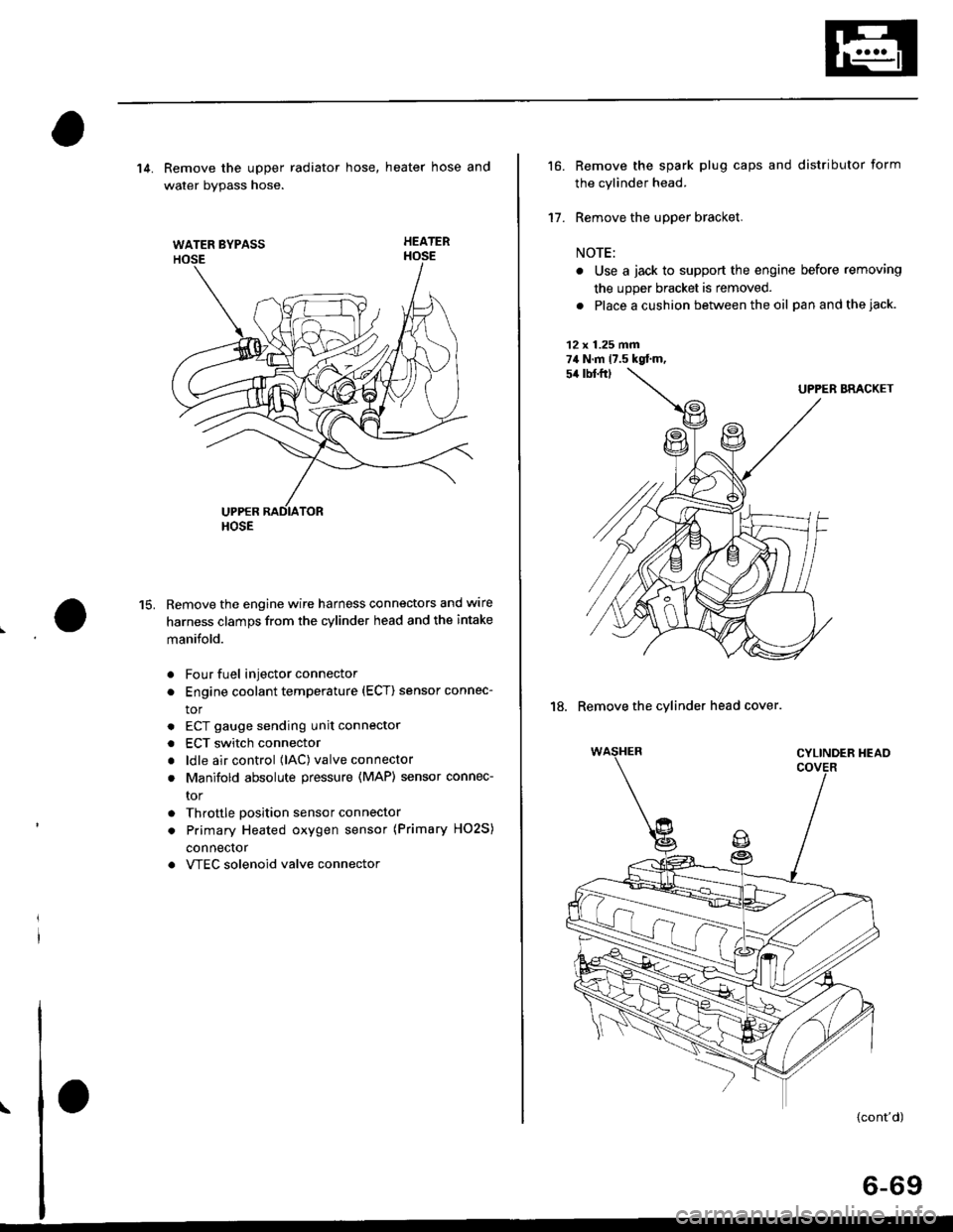
WATER BYPASS
HOSE
14. Remove the upper radiator hose, heater hose and
water bvpass hose.
HEATER
Remove the engine wire harness connectors and wlre
harness clamps from the cylinder head and the intake
manifold.
Four fuel injector connector
Engine coolant temperature (ECT) sensor connec-
tor
ECT gauge sending unit connector
ECT switch connector
ldle air control (lAC) valve connector
Manifold absolute pressure (MAP) sensor connec-
tor
Throttle position sensor connector
Primary Heated oxygen sensor (Primary HO2S)
connecror
VTEC solenoid valve connector
15.
a
a
a
a
a
\
16.
17.
Remove the spark plug caps and distributor form
the cylinder head.
Remove the upper bracket.
NOTE:
. Use a jack to support the engine before removing
the upp€r bracket is removed.
. Place a cushion between the oil panandthejack.
12 x 1.25 fin74 N.m 17.5 kgtm,
UPPER BRACKET
18. Remove the cylinder head cover.
{cont'd)
6-69
Page 270 of 2189

!
Fuel and Emrsslons
SoecialToofs .....,...."..,. 11-2
Component Locations
lndex ....................., ......... 11-3
Svstem Description
Vacuum Connections ................,,..,.. ......... 11-12
Electrical Connections ...............,.,.,... ....... 11-29
System Connectors ........,.,.,.......................... 1 1-51
Troubleshooting
Troubleshooting Procedures ................. .. 11-81
Engine Control Module/PowertrainControl Module TerminalAfiangement ....,.,..... 11-88
Diagnostic Trouble Code Chart .................,., 11.97
How to Read Flowcharts .,.......................... . 11-103
PGM-Fl System
System Description ...... 11-10,1
Troubleshooting Flowcharts
Engine Control Module/PowertrainContlol Module ........ 11-107
Manitold Absolute Pressure Sensor .....'. . ... 11-115
fntake Air Temperatuie Sensor ..... . . ., . 11'121
Engine Coolant Temperatuae Sensol ........., 11-128
Throttle Position Sensor ...................,........... 11-132
Primary Heated Orygen Sensor (Sensor 1l ... 11-139
Secondary Heated Oxygen Sensor(Sensor 21.................................................... 1 1-153
Heated Oxygen Sensor Heater ...................,. 11-157
Fuel Supply System ...... 11-164
Random Mislire ......., ..11-166
Misfire Detected in One Cylindsr ................. 11-167
Knock Sensor .,.,............ 11-170
CKP/TDC/CYP Sensor ................................... 11'172
Vehicle Speed Sensor ...........,......,...,.,........... 1t-176
Barometric Pressure Sensor ...............,......... I 1-178
Electrical Load Detector,.,,............................ 1 1-179
CKF Sensor .................... 11-183
ECM/PCM Internal Circuit ............................. I 1-188
A/T Signal {TMA/TMBI .................................. I 1-189
ldle Control System
System Doscriplion ............ 11-190
Troubleshooting Flowcharts
ldle Control System ...... 11-192
ldle Air Control Va1ve .................................... I 1-19i1
Starter Switch Signal .................................... 1 1'202
Air Conditioning Signal ................................. 11'201
Ahernator FR Signal .................................... . 1 1-208
BrakeSwitch Signal ..................................... f 1"210
Power Sleering Prossure Switch Signal ......11-212
A/T Gear Position Signal ............................... 11-216
Clutch Swiich Signal ................................-.... 11-214
ldte Speed Setting . .............11-220
Fuel Supply System
Fuel Lines .,...................,.,.,.,11-221
Fuef Tube/Ouick-Connect Fittings ..........,.,........ 11 -227
System Description ....'.... 11-230
Fuel Pressure .......,.,,........... 11-230
Fuef fniectors ......................11-232
Fu€f Pressure Regulator .....,.......................'...,. 11-231
Fuef Fifter ............................11-235
Fuel Pump .............'.......'.... 11-236
PGM-FI Main Relay .............11'237
Fuel Tank ................ ....,...'.'.' 11'211
Intake Air System
System Description ....-.-.....11-243
Air Cfeaner ...........,......."". .11-211
Throttle Cable .....................11-211
Throttfe Body ........ ..'... . . .,.11-211
Fuel Iniestion Air Control System ,.,.,....-........... 11-250
Emission Control System
System Description .-..........11-252
Taifpip€ Emission ...............11-252
Three Way Catafytic Convert€r ............,.,,.,.,.,.... 11 -252
Exhaust Gas Racirculaiion System ...,.,,,,.,.,.,.,,. 11'254
Positive Crankcas€ Ventilation System .... . . .. 11-266
Evaoorative Emission Controls ..................,,..,.,. 11 -267
Page 272 of 2189
Gomponent Locations
L
lndex
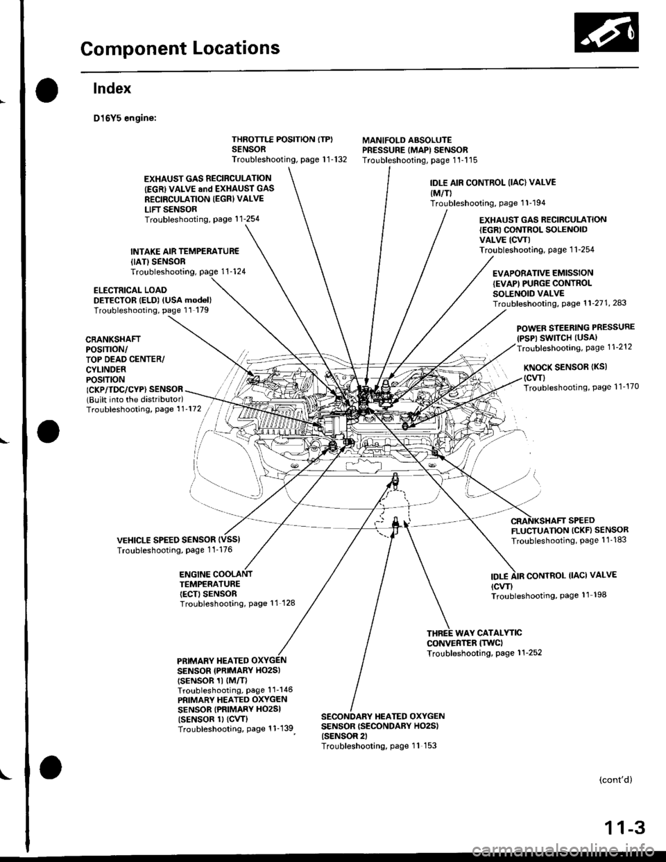
D16Y5 engine:
{IATISENSORTroubleshooting,
ELECTRICAL LOADDETECTOR IELD) (USA mod6l)Troubleshooting, page 11 179
THROTTLE POSITION ITP)SENSORTroubleshooting, page 1 1-132
MANIFOLD ABSOLUTEPRESSURE IMAPI SENSORTroubleshooting, page 1'l-115
EXHAUST GAS RECIRCULATION
IEGRI VALVE and EXHAUST GAS
RECIRCULATION IEGRI VALVE
LIFT SENSORTroubleshooting, page'l 1-254
INTAKE AIR TEMPERATUR€
IDLE AIR CONTROL (IAC) VALVE
{M/T)Troubleshooting, page 1 1-194
EXHAUST GAS RECIRCULATION{EGRI CONTROL SOLENOIDVALVE ICW)Troubleshooting. page 1 1-254
EVAPORATIVE EMISSIONIEVAPI PUNGE CONTROLSOLENOID VALVETroubf eshooting, Page 1 1'21 1, 243
CRANKSHAFTPOS|TTON/TOP DEAD CENTER/CYLINDERPOS|T|ON
POWER STEERING PRESSURE(PSP) SWITCH (USAI
Troubleshooting, Page 1 1-212
KNoCK SENSoR (Ks)
(cwl
Troubleshooting, Page 1 1'170ICKP/TDC/CYP} SENSOR(Built into the distributor)Troubleshooting, Page 1 1'172
VEHICLE SPEED SENSORTroubleshooting, Page 1 1-176
FLUCTUATION (CKF} SENSOR
Troubleshooting, Page 1 1 -183
ENGINE COOLANTTEMPERATUREIECT) SENSORTroubleshooting, Page 11 128
IDT.ECONTROL IIACI VALVE
{cw)Troubleshooting, Page 11 198
WAY CATALYTICCONVERTER ITWCITroubleshooting, Page 1 1-252PRIMARY TIEATEDSENSOR {PNIMARY HO2SI
tsENsoR 1t {M/TlTroubleshooting, Page'l 1-146
PRIMARY HEATED OXYGENSENSOR (PRIMARY HO2SI
tsENsoR 1l {cw}Troubleshooting, Page 1 1-139
SECONDARY HEATED OXYGENSENSOR {SECONDARY HO2S){SENSOR 2)Troubleshooting, page 11 153
(cont'd)
1 1-3
Page 273 of 2189
Component Locations
Index (cont'd)
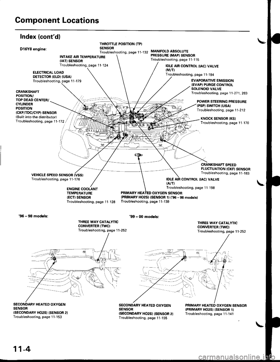
D16Y8 enginc:
THROTTLE POSITION {TPISENSORTroubleshooting, page 1 1-132
ELECTRICAL LOADDETECTOR IELDI {USAI
INTAKE AIR TEMPERATUREIIATISENSORTroubleshooting, page 1 1,124
MANIFOLO ABSOLUTEPRESSURE {MAPI SENSORTroubleshooting, page 1 1-1 15
IDI.E{A/T)
IDI.E AIR CONTROL IIACI VALVElMtflTroubleshooting, page 1 1-194
Troubleshooting, page 1 1-179EVAPORATIVE EMISSIONIEVAPI PURGE CONTROLSOLENOIO VALVETroubleshooting, page 1 1 27 1. 283CRANKSHAFTPOSTTTON/TOP DEAD CENTER/CYLINDERPOStTtON
POWER STEERING PRESSURE(PSPI SWTTCH |USA)Troubleshooting, page 1 1-212{CKP/TI'C/CYPI SENSOR(Built into the distributor)Troubleshooting. page 1 1-172KNOCK SENSOR IKSITroubleshooting, page 11 170
CRANKSHAFT SPEEDFLUCTUANON ICKFI SENSORTroubleshooting, page 1 1,183
CONTROL {IACI VALVE
ENGINE COOLANTTEMPERATURE{ECTI SENSORTroubleshooting, page 11 128
Troubleshooting, page 11 198
PRIMARY HEATED OXYGEN SENSOR{PRIMARY HO2S} (SENSOR 1l {'96 - 98 modolslTroubleshooting, page 1 1-139
'9!t - 00 modols:'96 - 98 modols:
THREE WAY CATALYNCCONVERTER ITWCITroubl6shooting, page 1 1-252
THREE WAY CATALYNCCONVERTER ITWCITroubleshooting. page 1 1-252
SECONDARY HEATED OXYGENSENSOn(SECONDARY HO2SI (SENSOR 2ITroubleshooting, page 1 1-153
SECONDARY HEATED OXYGENSENSOBISECONDARY HO2S} ISENSOR 2ITroubloshooting, page 1 1-155
PRIMARY HEATEO OXYGEN SENSORIPRIMARY HO2SI ISENSOR 1ITroubleshooting, page 1 1-141
11-4
Page 274 of 2189
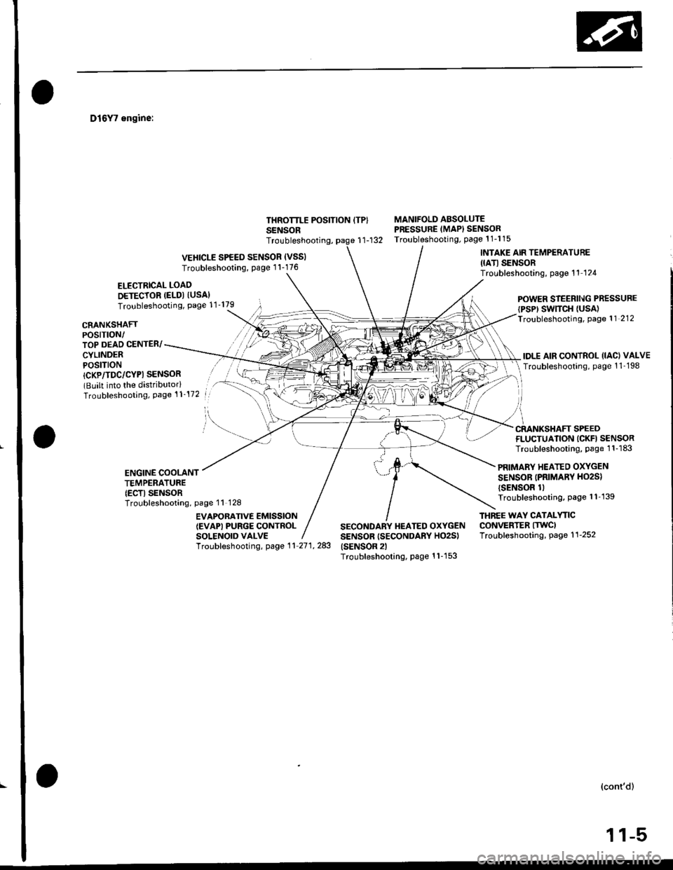
D16Y7 engine:
ELECTRICAL LOAO
DETECTOR (ELD) IUSA}Troubleshooting, Page 11'179
THROTTLE POSITION ITPISENSOR
MANIFOLD ABSOLUTEPRESSURE (MAPI SENSORTroubleshooting, Page 1 1-1 15r1-132
CRANKSHAFTPOSTTTON/TOP DEAD CENTER/
CYLINDERPOSITION
POWER STEERll\lG PRESSURE
{PSP' SWTTCH {USA)Troubleshooting, Page 11 212
IDLE AIR CONTROL (IAC) VALVE
Troubleshooting, page 1 1-198
Troubleshooting,
VEHICLE SPEED SENSOR (VSSI
Troubleshooting, Page 1 1-176
INTAKE AIR TEMPERATURE
IIATI SENSORTroubleshooting, page 11 124
l
/i
CRANKSHAFT SPEED
{CKP/TDC/CYPI SENSOR(Built into the distributorlTroubleshooting, Page 't 1-172
FLUCTUATION ICKFI SENSORTroubleshooting, Page 1 1-183
PRIMARY HEATED OXYGEN
SENSOR (PRIMARV HO2S)
{SENSOR 1lTroubleshooting, page 1 1'139
ENGINE COOLANTTEMPERATURE(ECTI SENSORTroubleshooting, page 11 128
EVAPOBATIVE EMISSION(EVAPI PURGE CONTROLSOLENOID VALVE
THNEE WAY CATALYTICCONVERTER ITWCITroubleshooting, page 1 1-252
Troubf eshooting, page 1 1 27 1, 283
SECONDARY HEATED OXYGENSENSOR (SECONDARY HO2S)(SENSOR 2lTroubleshooting, Page 1 1-1 53
(cont'd)
,l .ltr| | -r,
Page 275 of 2189
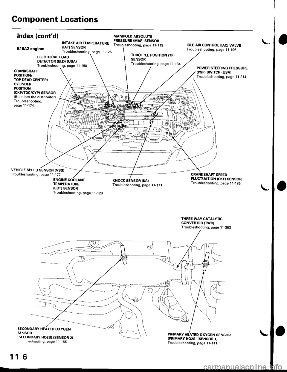
Component Locations
Index (cont'dl
Bl6A2 engine:
INTAKE AIR TEMPERATURE{IAT} SENSORTroubleshooting, page 1'1-125
MANIFOLO AESOLUTEPRESSURE IMAPI SENSORTroubleshooting. page 11-1 19IOLE AIR CONTROL {IAC) VALVETroubleshooting, page 1 1,196
ELECTRICAL LOADDETECTOR IELDI (USA)
Troubleshooting, page 1 1-180
THROTTLE POSITION ITPISENSORTroubleshooting, page 11-134
CRANKSHAfiPOStTtON/TOP DEAD CENTER/CYLINDERPOStTtON{CKP/TDC/CYPI SENSOR(Bualt into the distributor)Troubleshooting,page 11-174
POWER STEERING PRESSURE{PSPI SWTTCH (USA)
Troubleshooting, page 1 1-214
VEHICLE SPEED SENSOR {VSS}Troubleshooting, page 1 1-177
ENGINE
CRANKSHAFT SPEEDFLUCTUATION (CKFI SENSORTroubleshooting, page 11- t85TEMPERATUREIECTI SENSORTroubleshooting, page I 1-128
THREE WAY CATALYTICCONVERTER ITWC)Troubleshooting, page 1 1,252
S€CONOARY HEATED OXYGENsf rlsoR
sfCoNDARY HO2SI {SENSOR 2): ?shootrng, page 11 155
-6
PRIMARY HEATED OXYGEN SENSORIPRIMARY HO2S) ISENSOR 1ITroubleshooting, page 1 1-141
11
Page 354 of 2189
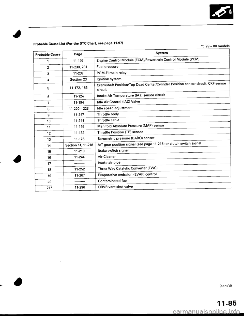
Probable Cause List lFor th€ DTC Chart, see page 11-971*: '99 - 00 models
Probable GausePageSystem
11 1-107Engine Control Module (ECM)/Powertrain Control Module (l'uM)
PGM-Fl main relay
l^^iti^n cwetam
211-230,231
3't't-237
Section 23
51'�1-172,183Crankshaft Position/fop Dead Center/Cylinder Fosltlon sensor clrculr'� Lr\F selrsor
circuit
Intake Air Temperature (lAT) sensor circuit
ldle Air Control (lAC) Valve
ldle speed adjustment
Throttle bodY
Throftle cable
Manifold Absolute Pressure (MAP) sensor
Throftle Position (TP) sensor
Barometric pressure (BARO) senso'
Mf g"a, po"ition signal (see page 11-216) or clutch switch signal
Brake switch signal
Air Cleaner
lntake air pipe
Three Way Catalytic Converter (TWC)
Evaporative emission (EVAP) control
Contaminated fuel
ORVR vent shut valvs
't1-124
71 1-194
I11-220 - 223
11-241
'1011-244
1111-115
1211-132
13't1-178
14Section 14. 11-218
1511-210
16't1-244
1811-252
1911-261
20
21*11-296
(cont'd)
11-85
Page 356 of 2189
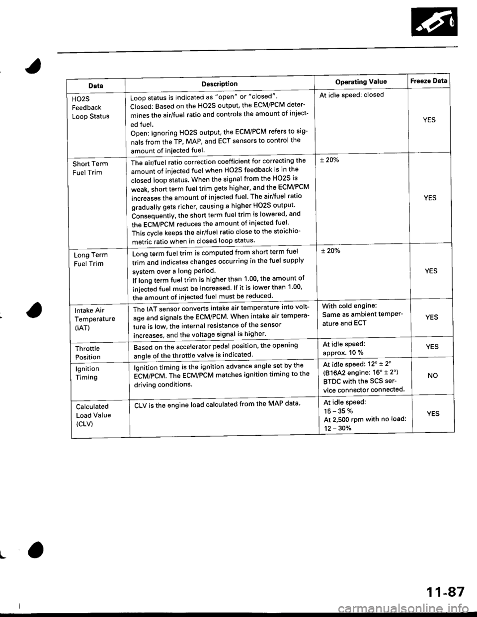
DataDescriotion
Loop status is indicated as "open" or "closed"'
Closed: Based on the HO2S output, the ECM/PCM deter-
mines the airlfuel ratio and controls the amount of inject-
ed fuel.
Open: lgnoring HO2S output, the ECM/PCM refers to sig-
nals from the TP, MAP, and ECT sensors to control the
amount of injected fuel.
The air/fuel ratio correction coefficient for correcting the
amount ot injected fuel when H02S feedback is in the
closed loop status When the signal from the HO2S is
weak, short term fuel trim gets higher, and the ECM/PCM
increases the amount of injected fuel The airlfuel ratio
gradually gets richer, causing a higher HO2S output
Consequently, the short term fuel trim is lowered, and
the ECMiPCM reduces the amount of injected fuel
This cvcle keeps the airlfuel ratio close to the stoichio-
metric ratio when in closed loop status'
Operating ValueF eeza Data
HO2S
Feedback
Loop Status
At idle speed: closed
YES
Short Term
Fuel Trim
! 20%
YES
Long Term
Fuel Trim
Long term fuel trim is computed from shon term fuel
trim and indicates changes occurring in the fuel supply
svstem over a long Period
lf long term fuel trim is higher than 1.00, the amount of
injecGd fuel must be increased. lf it is lower than 1 00'
the amount of injected fuel must be reduced'
! 20%
YES
lntake Air
Temperature
{IAT)
The IAT sensor converts intake air temperature into volt-
age and signals the ECM/PCM. When intake air tempera-
ture is low, the internal resistance of the sensor
increases. and the voltaqe signal is higher'
With cold engine:
Same as ambient temPer'
ature and ECTYES
At idle speed:
approx. 10 %YESThrottle
Position
Based on the accelerator pedal position, the open'ng
angle of the throttle valve is indicated
lgnition
Timing
lgnition timing is the ignition advance angle set by the
gCV/eCV. tn" gCU/PCM matches ignition timing to the
driving conditions.
CLV is the engine load calculated from the MAP data'
At idle speed: 12'i 2'
(81642 engine: 16" t 2")
BTDC with the SCS ser-
vice connector connected.
NO
Calculated
Load Value
{CLV)
At idle speed:
15-35%
At 2.500 rpm with no load:
12 - 30%
YES
ro
11-87
Page 360 of 2189
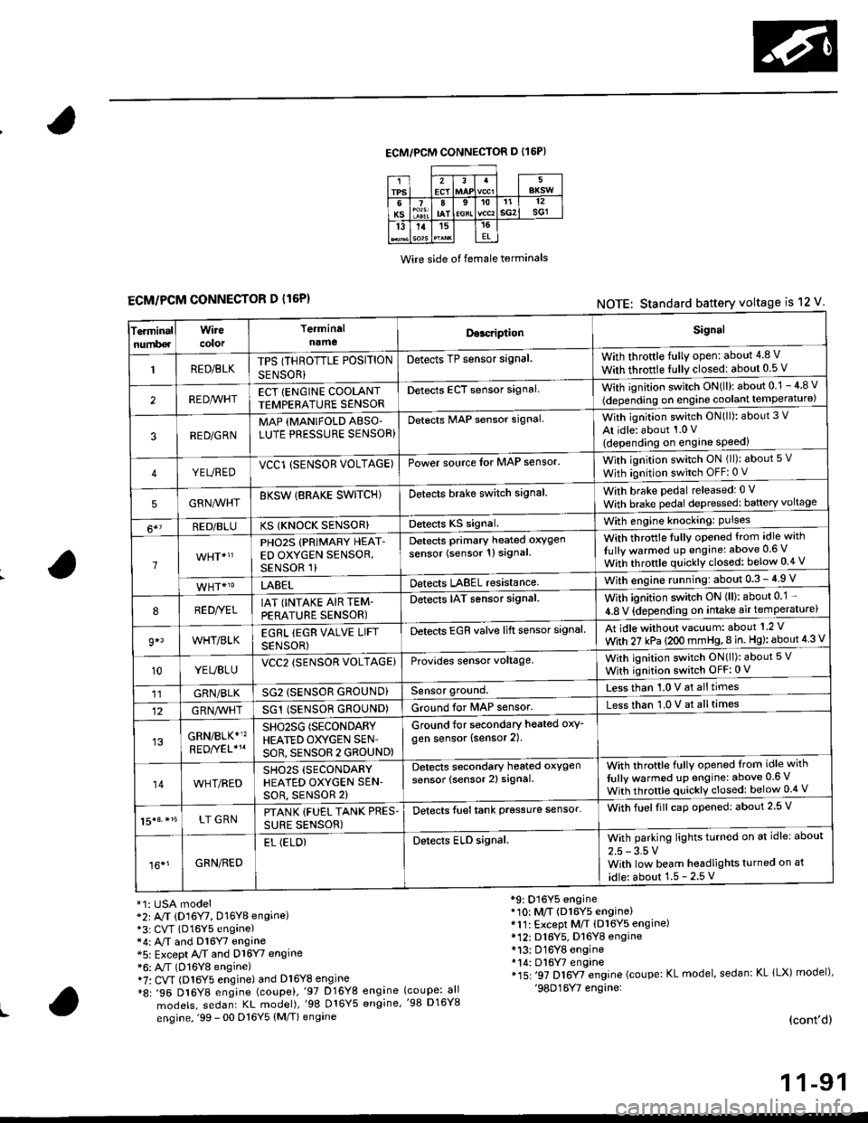
ECM/PCM CONNECTOR D I16P)
Wire side ot female terminals
ECM/PCM CONNECTOR D l16P)NOTE: Standard battery voltage is 12 V
Te.minalnumb€r
Wirecolor
Terminaln!meDor.riptionSignal
RED/BLKTPS (THROTTLE POSITION
SENSOR}
Detects TP sensor signal.With throttle fully open: about 4.8 V
With throttle fully closedl about 0.5 V
REDA/VHTECT {ENGINE COOLANTTEMPERATURE SENSORDetects ECT sensor signalWith ignition switch ON{ll): about 0.1 - 4 8 v
(depending on engine coolant lempe ratu re)
3RED/G RNMAP {MANIFOLD ABSO'LUTE PRESSURE SENSOR}Detects MAP sensor signal.With ignition switch ON(ll): about 3 V
At idle: about 1.0 V
{depending on engine speed)
YEUREDVCCl (SENSOR VOLTAGE)Power source lor MAP sensor.With ignition switch ON (ll): about 5 v
With ignition switch OFF: 0 V
5GRNMHTBKSW {BRAKE SWITCHIDetects brake switch signalWith brake pedal released: 0 v
With brake pedal depressed: baftery voltage
6*?RED/BLUKS {KNOCK SENSOR}Detects KS signal.With engine knocking: Pulses
1
PHO2S (PRIMARY HEAT-ED OXYGEN SENSOR,SENSOR 1)
Detects Primary heated oxygen
sensor (sensor 1l signal
With throttle fullv opened from idle with
Iully warmod up engine: above 0.6 V
With throttle quickly closed: below 0.4 v
LABELDetects LABEL resistanceWith engine r!nning:about 0.3 - 4.9 V
8RED//ELIAT (INTAKE AIR TEM-PERATURE SENSOR)
Detects IAT sensor signal.With ignition switch ON (ll): about 0 1 -
4.8 V {depending on intake air temperature)
9*lWHT/BLKEGRL iEGR VALVE LIFT
SENSOR)
Detects EGR valve lift sensor signalAt idle without vacuum: about'1 2 V
With 27 kPa (2OO mmHg,8 in. Hg): about 4 3 V
10YEUBLUVCC2 (SENSOR VOLTAGE)Provides sensor voltage,With ignition switch ON(ll): about 5 V
With ignition switch OFF:0 V
11GRN/BLKSG2 (SENSOR GROUND}Sensor ground.Less than 1.0 V at alltimes
12G RN,4/1r'HTSG1 (SENSOR GROUND)Ground for MAP sensor.Less than 1.0 V at alltimes
GRN/BLK*1?SHO25G (SECONDARY
HEATED OXYGEN SEN'
SOR, SENSOR 2 GROUND)
Ground for secondary heated oxy-
gen sensor (sensor 2).
14WHT/REDSH02S (SECONDARY
HEATED OXYGEN SEN'soR, sENsoR 2)
Detects secondary heated oxygen
sensor (sensor 2) signal.With throftle fully opened lrom idle with
fully warmed up engine: above 0.6 V
With throttle quickly closed: below 0.4 V
15|3. *15LT GRNPTANK {FUEL TANK PRES.
SURE SENSOR)
Detects fueltank prgssure sensor'With fuelfill caD opened: about 2.5 V
16*1GRN/RED
EL (ELD)Detects ELD signal.With parking lights turned on at idle: about
2.5 - 3.5 VWith low beam headlights turned on at
idle: about 1.5 - 2.5 V
*1: USA model*2r A/T (D16Y7, D16Y8 engine)*3: CVT (D16Y5 engane)*4: A,/T and Dl6Y7 engine*5: Except A/T and D16Y7 engine*6: A"/T (D16Y8 engine)i7: CVT (Dl6Y5 engine) and Dl6Y8 engine*8: .96 D16Y8 engine (coupei,'97 D16Y8 engine
models, sedanr KL model),'98 016Y5 engine,
engine, '99 - 00 D16Y5 (M/T) engine
*9: D16Y5 engine*10: M/T (D16Y5 engine)*11: Except M/T (Dl6Y5 engine)* 12r D16Y5. D16YB engine*13: D16Y8 engine*14: Dl6W engine*15: '97 D16Y7 engine (coupe: KL model, sedan: KL lLX) model),'98D16Y7 engine:(coupe: all'98 D16Y8
(cont'd)
1 1-91