out HONDA CIVIC 1996 6.G Workshop Manual
[x] Cancel search | Manufacturer: HONDA, Model Year: 1996, Model line: CIVIC, Model: HONDA CIVIC 1996 6.GPages: 2189, PDF Size: 69.39 MB
Page 2 of 2189
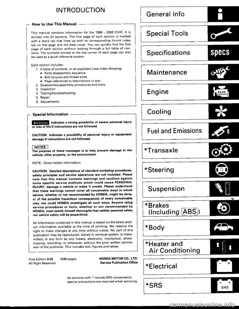
INTRODUCTION
How to Use This Manual
This manual contains information for the 1996 - 2000 ClVlC. lt is
divided into 24 sections. The first page of each section is marked
with a black tab that lines up with its corresponding thumb index
tab on this page and the back cover. You can quicklY find the first
page of each section without looking through a tull table ol con_
tents. The symbols printed at the top corner of each page can also
be used as a quick reference system.
Each section includesl
1. A table of contents, or an exploded view index showing:
. Parts disassemblY sequence.
. Bolt torques and thread sizes.
. Page references to descriptaons in text
2. Disassembly/assembly procedures and tools.
3. Inspection.
4. Testing/troubleshooting.
5. Repair.
6. Adjustments.
Special Information
!@ Indicates a sttong possibility of sover. perconal iniurY
or loss ol lite if in3tructions are not follow€d.
GAUTION: Indicaiqs a possibility ot p€lsonal injury or 6quipm.nt
damage il instiuc'tions are not followod
t Noncali-. pu.po.. ot thes6 messages is to help provent demage lo lhe
vehicle, other property, or the €nvironment.
NOTE: Gives helpful information.
CAUTfON: Detaifed descriptions ol standard workshop p.oceduro3.
safoty principles and servico operations are not included. Pleaso
note that this manual contain3 wetnings and cautions against
some sp6cific sGrvic€ methods which could cause PERSONAL
INJURY, damage a vohicle or make il unsafe. Ploase undorstand
that these warnings cannot covsr all conceivable weys in which
service. whelher or not iocommgndod bY HONDA. mighi bo done,
or ol tho possiblG hazardou3 consgquonces of ev€aY conceivablg
way, nor could HONDA invqstigato all 3uch way3. AnYono using
sgrvice procedures or lools, whethei or nol rGcommendod bY
HONDA, must srtisty hifisetf thoroughlylhat nohher pefsonal sefety
nor vehiclc satsty will be reopardi2ed.
All intormation contained in this manual is based on the latest prod
uct information available at the time oI printing We reserve the
right to make changes at any time without notice No part of this
publication may be reproduced, stored in retrieval system, or trans'
mitted, in any form by any means, electronic, mechanical, photo
copying, recording, or otherwise, without the prior written permis-
sion of the publisher. This includes text, figures and tables.
*Transaxle
ds
First Edition 8/99 1848 PagesAll Right Reserved
HONOA MOTOR CO., LTD.
Sorvico Publication Offico
As sections with * include SRS components;
sDecial precautions are lequired when servlclng
*Electrical't
*SRSSRS
Page 35 of 2189
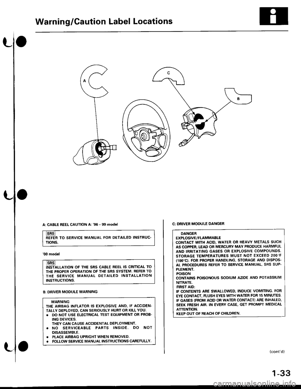
Warning/Caution Label Locations
A: CABLE REEL CAUTION A: '96 -99 model
TO SERVICE MANUAL FOR DETAILED INSTRUC.
TtoNs.
'00 model
ALLATION OF THE SRS CAELE REEL IS CRITICAL TO
THE PROPER OPERATION OF THE SRS SYSTEM. REFER TO
THE SERVICE MANUAL DETAILED INSTALLATION
INSTRUCTIONS.
(cont'd)
1-33
C: DRIVER MODULE OANGER
DANGEREXPLOSIVE/FLAMMABLECONTACT WITH ACIO. WATER OR HEAVY METALS SUCH
AS COPPER. I.EAD OR MERCURY MAY PRODUCE HARMFUL
AND IRRITATING GASES OR EXPLOSIVE COMPOUNDS,
STOBAGE TEMPERATURES MUST NOT EXCEED 2OO'F
I1(x}"CI. FOR PROPER HANDLING. STORAGE AND DISPOS.
AL PROCEDURES REFER TO SERVICE MANUAL. SRS SUP.
PLEMENT.POTSONCONTAINS POISONOUS SODIUM AZIOE AND POTASSIUM
NITRATE.FIRST AID:IF CONTENTS ARE SWALLOWED, INDUCE VOMITING, FOB
EYE CONTACT. FLUSH EYES WTTH WATER FOR 15 MINUTES.
IF GASES {FNOM ACIO OR WATEB CONTACTI ARE INHALED,
SEEK FRESH AIR. IN EVERY CASE, GET PBOMPT MEDICAL
ATTET,ITION.KEEP OUT OF REACH OF CHILDREN.
Br oRIVER MODULE WARNING
WARNINGTHE AIRBAG INFLATOR IS EXPLOSIVE AND, IF ACCIOEN-
TALLY DEPLOYEO, CAN SERIOUSLY HURT OR KILL YOU.. DO NOT USE ELECTRICAL TEST EoUIPMENT oR PROB-
ING OEVICES.THEY CAN CAUSE ACCIDENTAL DEPLOYMENT.o NO SERVICEABLE PARTS lNSlDE. DO NOT
DISASSEMBLE.. PLACE AIRBAG UPRIGHT WHEN REMOVED.. FOLLOW SERVICE MANUAL NSTBUCTIONS CAFEFULLY.
Page 37 of 2189
Llo
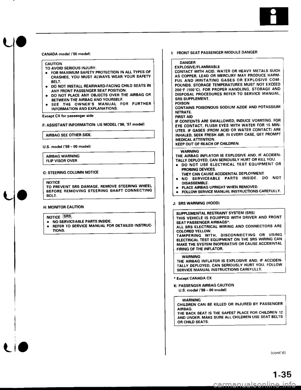
CANADA model ('00 model)
CAUTIONTO AVOID SERIOUS INJURYT. FOR MAXIMUM SAFETY PROTECTION lN ALL TYPES OF
CRASHES, YOU MUST ALWAYS WEAR YOUR SAFETY
BELT.. DO NOT INSTALL REARWARD-FACING CHILD SEATS lN
ANY FRONI PASSENGER SEAT POSITION.
. DO NOT PLACE ANY OBJECTS OVER THE AIRBAG OR
BETWEEN THE AIRBAG AND YOURSELF.. SEE THE OWNER'S MANUAL FOR FURTHER
INFORMATION AND EXPLANATIONS.
Except Cx tor passenger side
F: ASSISTANT INFoRMATION: US MODEL ('96. '97 mod€l)
AIRBAG SEE OTHER SIDE,
U.S. model l'98 - 00 modell
AIRBAG WARNINGFLIP VISOR OVER
Llo
G: STEERING COLUMN NOTICE
NOTICETO PBEVENT SRS DAMAGE, REMOVE STEERING WHEEL
BEFORE REMOVING STEERING SHAFT CONNECTING
BOLT.
ll: MONITOR CAUTION
NOTICE. NO SERVICEABIf PABTS lNSlDE.. REFER TO SERVICE MANUAL FOR DETAILED INSTRUC'
TtoNs.
DANGEREXPLOSIVE/FLAMMABLECONTACT WITH ACID, WATER OR HEAVY METALS SUCH
AS COPPER, LEAD OR MERCURY MAY PRODUCE HARM.
FUL AND IRRITATING GASES OR EXPLOSIVE COM-
POUNDS, STORAGE TEMPERATURES MUST NOT EXCEED
2OO'F I1OO"C}. FOR PROPER HANOLING, STORAGE AND
DISPOSAL PNOCEDURES REFER TO SERVICE MANUAL'
SRS SUPPLEMENT.POISONCONTAINS POISONOUS SODIUM AZIDE AND POTASSIUM
NITRATE.FIRST AIDIF CONTENTS ARE SWALLOWEO, INDUCE VOMITING. FOR
EYE CONTACT, FLUSH EYES WITH WATEB FOR 15 MIN-
UTES. IF GASES IFROM ACID OB WATER CONTACT) ABE
INHALED. SEEK FRESH AIR. IN EVERY CASE, GET PROMPT
MEDICAL ATTENTION.KEEP OUT OF REACH OF CHILDREN,
WARNINGTHE AIRBAG INFLATOR IS EXPLOSIVE AND, IF ACCIDEN-
TALLY OEPLOYED, CAN SERIOUSLY HUBT OR KILL YOU.
. DO NOT USE ELECTRICAL TEST EOUIPMENT OR
PROBING DEVICES.TH€Y CAN CAUSE ACCIDENTAL DEPLOYMENT'
. NO SERVICEABLE PABTS lNSlDE. oO NoT
DISASSEMBLE.. PLACE AIRBAG UPRIGHT WHEN REMOVED. FOLTOW SERVICE MANUAL INSTRUCTIONS CAREFULLY
I: FRONT SEAT PASSENGER MOOULE DANGER
Jr SRS WARNING IHOOD)
' Exceot CANADA CX
K: PASSENGER AIRBAG CAUTION
u.S. model l'98 - 00 model)
WARNINGCHILDREN CAN 8E KILLED OR INJUREO BY PASSENGER
AIRBAG,THE BACK SEAT IS THE SAFEST PLACE FOR CHILDREN 12
AND UNDER. MAKE SURE ALLCHILDREN USE SEAT BELTS
OR CHILD SEATS.
(cont'd)
1-35
SUPPLEMENTAL RESTRAINT SYSTEM ISRS}
THIS VEHICLE IS EOUIPPED WITH DBIVER AND FRONT
SEAT PASSENGER AIRBAGS'.ALL SRS ELECTRICAL WIRING AND CONNECTORS ABE
COLORED YELLOW.TAMPERING WITH, DISCONNECTING OR USING
ELECTRICAL TEST EOUIPMENT ON THE SRS WIRING CAN
MAKE THE SYSTEM INOPERATIVE OR CAUSE ACCIDENTAL
FIRING OF THE INFLATOR.
WARNINGTHE AIRBAG INFLATOR IS EXPLOSIVE AND, IF ACCIDEN.
TALLY DEPLOYED, CAN SERIOUSLY HURT YOU. FOLLOW
SERVICE MANUAL INSTRUCTIONS CAFEFULLY'
Page 39 of 2189
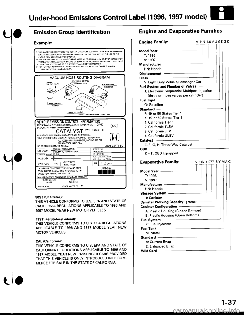
Under-hood Emissions Control Label (1996, 1997 model)
Emission
Example:
Group ldentification
VACUUM HOSE ROUTING DIAGRAM
50ST {50 States):
THIS VEHICLE CONFORMS TO U.S, EPA AND STATE OF
CALIFORNIA REGULATIONS APPLICABLE TO 1996 AND
1997 MODEL YEAR NEW MOTOR VEHICLES.
/$ST (49 States/Federall:
THIS VEHICLE CONFORMS TO U.S. EPA REGULATIONS
APPLICABLE TO '1996 AND 1997 MODEL YEAR NEW
MOTOB VEHICLES,
CAL (Calitornis):
THIS VEHICLE CONFORMS TO U.S. EPA AND STATE OF
CALIFORNIA REGULATIONS APPLICABLE TO 1996 AND,1997 MODEL YEAR NEW PASSENGER CARS PROVIDED
THAT THIS VEHICLE IS ONLY INTROOUCED INTO COM-
MERCE FOR SALE IN THE STATE OF CALIFORNIA.
-VEHICLE Ei/ ISSION CONTROL INFORMATIONE\G\. rrMrr vtsNrs\JLK6\Dsp-A(.MFN 590(--,. O CIVIC fa:n!APOF!]V4 -AV.t' !-rirorrSrMAc \Y:/
CATALYST IwcN02S{2)sFr
Fl.tarostq! tMA\uAttoaaooTo\a- \'oFM^ ro rt Tlr. \F Jo(O\D ' O\S E\Gr\l AINOnMA-OolqllNCTMoEqA Uql lH ia-LACCESSoT rS r-F\Eo0F C00ll\G -A 0( \-!-lJTRANSM1SSION N NEUTFAINO OTHERAOJUSIMENTS NEEDEO. O8D IICERTIFIED
IDLESPEEOATDC
NDr(Jl6CR.L1lr.r -i, "
TH SVEH CLE CONfOFMSTO U S. EPA AND STATEOF CALfORNIA RECULAI ONSAPPLICA8IElO 1997MOOET YEAR NEW MOTOR VEH CL'Silil]]lrl
Er!4#_"E!!ifl 4q!sq+HT-q4E!rL
N US€ TIEB l FULL
11211 .?2E AO2 HONDA MoTOR C0 , tTD
Engine and EvaPorative Families
Engine Family:V HN l.6VJGKGK
Model Year
T: 1996
V: 1997
T I
T|I
Manufacturer
HN: Honda
Displacem€nt
V: Light Duty Vehicle/Passenger Car
Fuel Systsm and Number of valves
J: Electronic Sequential Multiport Injection
(three or more valves per cylinder)
Fuel Type
G: Gasoline
Standard
F: 49 or 50 States Tier 1
K: 49 or 50 States Tier 1
1:California Tier 1
2: California TLEV
3: California LEV
4; California ULEV
Catalyst
E, F, G. H: Three Way Catalyst
OBD
K - T: OBD Equipped
Evaporative Family: v HN 1077 BYMAc'|T
Model Year
T:1996 |V:1997 lManufacturel
HN: Honda
Storage System
1:Canister
Canister Working Capacity (grams)
Canister Configulation
A: Plastic Housing (Closed Bottom)
B: Plastic Housing (oPen Bottom)
Fuel Systsm
Y: Fuel Injection
Fuel Tank
M: Metal
Standard
A: Current Evap
E: Enhanced Evap
Wild Card
1-37
Page 45 of 2189
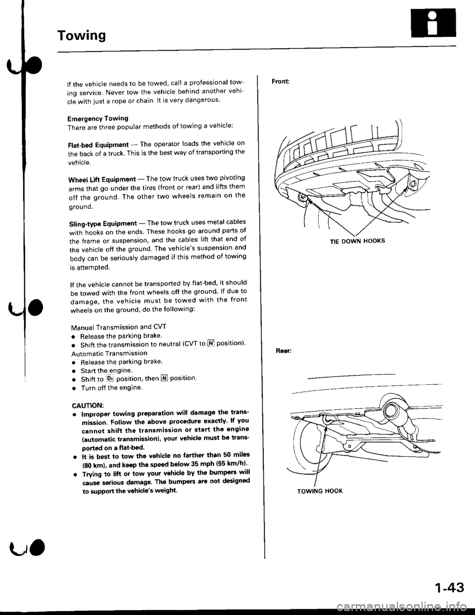
Towing
lf the vehicle needs to be towed, call a professional tow-
ing service. Never tow the vehicle behind another vehi
cle with iust a rope or chain lt is very dangerous'
Emergency Towing
There are three popular methods of towing a vehicle:
Flat-bed Equipment - The operator loads the vehicle on
the back of a truck. This is the best way of transporting the
vehicle.
Wheel Lift Equipment - The tow truck uses t\ivo pivoting
arms that go under the tires {front or rear} and lifts them
off the ground. The other two wheels remain on the
ground.
Sling-type Equipment - The tow truck uses metal cables
with hooks on the ends. These hooks go around parts of
the frame or suspension, and the cables lift that end of
the vehicle off the ground The vehicle's suspension and
body can be seriously damaged if this method of towing
is attemDted.
lf the vehicle cannot be transported by flat-bed. it should
be towed with the front wheels off the ground lf due to
damage, the vehicle must be towed with the front
wheels on the ground, do the following:
lvlanual Transmission and CW
. Release the parking brake
. Shift the transmission to neutral (CW to E position)'
Automatic Transmission
. Release the Parking brake.
. Sta rt the engine.
. Shift to LDll position, then E position.
. Turn oif the engine
CAUTION;
o lmploper towing preparation will damage ihe tfans-
mission. Follow the above procedute exaqtly lf you
cannot shift the tlansmission or start the engino
laulomatic transmissionl, yout vehicle must be trans-
ported on a flat-bed.
. lt is best to tow the vehicle no farther than 50 mil€s
(80 km), and ksop thE speed below 35 mph (55 km/hl
. Trying to lift 01 tow your vehicle by tho bump€F will
caus€ setious damagg. Ths bumpers are not dEigned
to supportthe vshicle's weigh.
tJO
1-43
Front:
Rear:
TIE DOWN HOOKS
TOWING HOOK
Page 47 of 2189
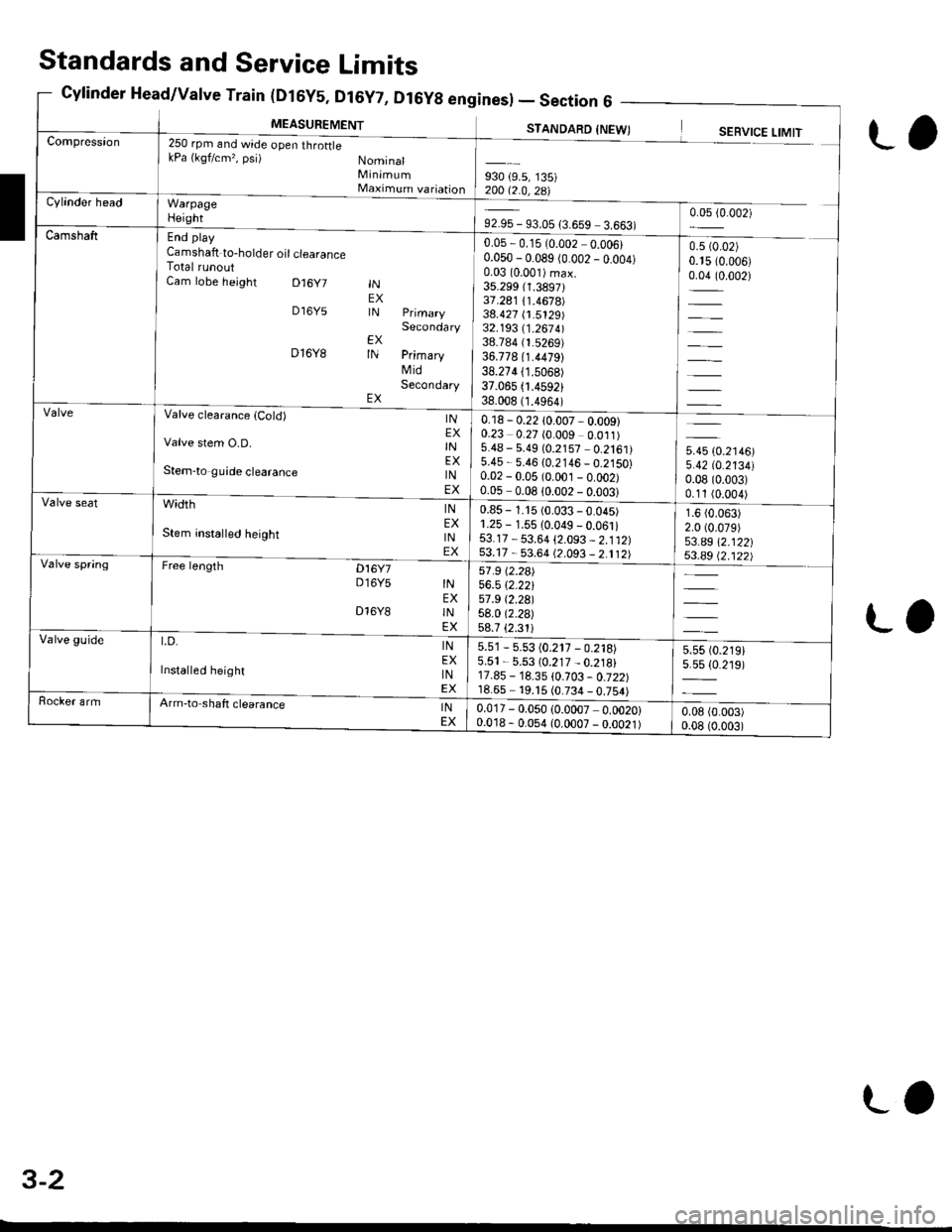
(urbY5, ul6Y7, Dl6Yg enl
MEASUREMENT
Sines) -Section6 -
STANDARD INFWTCompression250 rpm and wide open throftlekPa {kgf/cm,, psi) NominalMinimumMaximum variationWarpageHeight
End play
Camshaft to-holder oil clearanceTotal runoutCam lobe height D16y7
D16Y5
D16Y8
INEXIN
EXIN
EX
Secondary
PrimaryMidSecondary
930 {9.5, 135)200 12 0 ?R\Cylinder head
92.95 - 93.05 {3.659 3.663)0.05 {0.002)
Camshaft0.05,0.15 (0.002 0.006)0.050 - 0.089 (0.002 _ o.oo4)0.03 (0.001)max.
35.299 (1.3897131.241 /.1.4678)38.427 (1.5129)32.193 11 .267 4l38.784 (1.5269)
36.778 (1.4479)
38.274 (1.5068)
37.065 .4592)38.008 (1.4964)
0.5 (0.02)
0.15 (0.006)
0.04 (0.002)
=
Valve clearanca {Cold)
Valve stem O.D.
Stem-to guide clearance
width
Stem insta ed height
Free lengrh Dt6y7D16Y5
INEXINEXINEX
INEXINEX
INEXINEX
INEXINEX
D16Y8
t.D.
Installed height
0.18 - 0.22 10.007 - 0.009)0.23 0.27 (0.009 0.011)5.48 - 5.49 (0.2157 0.2161)5.45 - 5.46 {0.2146 _ 0.2150}0.02 - 0.05 (0.001 _ o.oo2)0.05-008lono2-nnn?l
5.45 (0.2146)
5.42 tO.213410.08 (0.003)
0.11 (0.004)
1.6 (0.063)
2.0 (0.079)
53.a9 \2.122|j$.a9 Q.122)
Valve seat0.85 - 1.15 (0.033 - 0.045)1.25 - 1.55 10.049 - 0.061i53.17 - 53.64 {2.093 _ 2.112)53.17 - 53.64 (2.093 _ 2.112)Valve spring57 .9 (2.2a)
56.5 \2.22157 .9 t2.29l58.0 (2.2a)
58.7 {2.31iValve guide5.51 - 5.53 (0.217 - 0.218)5.51 - 5.53 (0.217 _ 0.218)17.85 - 18.35 \0.103 - 0.722)18.65 19. t5 (0.734 _ 0.754)
5.55 t0.219)5.5s {0.219)
Rocker armArm-to shaft clearanceINEX0.017 - 0.050 (0.0007 0.0020)0.018 - 0.054 (0.0007 - 0.0021)0.08 (0.003)
0.08 (0.003)
Standards and Service Limits
Cylinder Head/Valve Train (Dt6y5, Dt6y7, D
L,
ra
3-2
LO
Page 48 of 2189
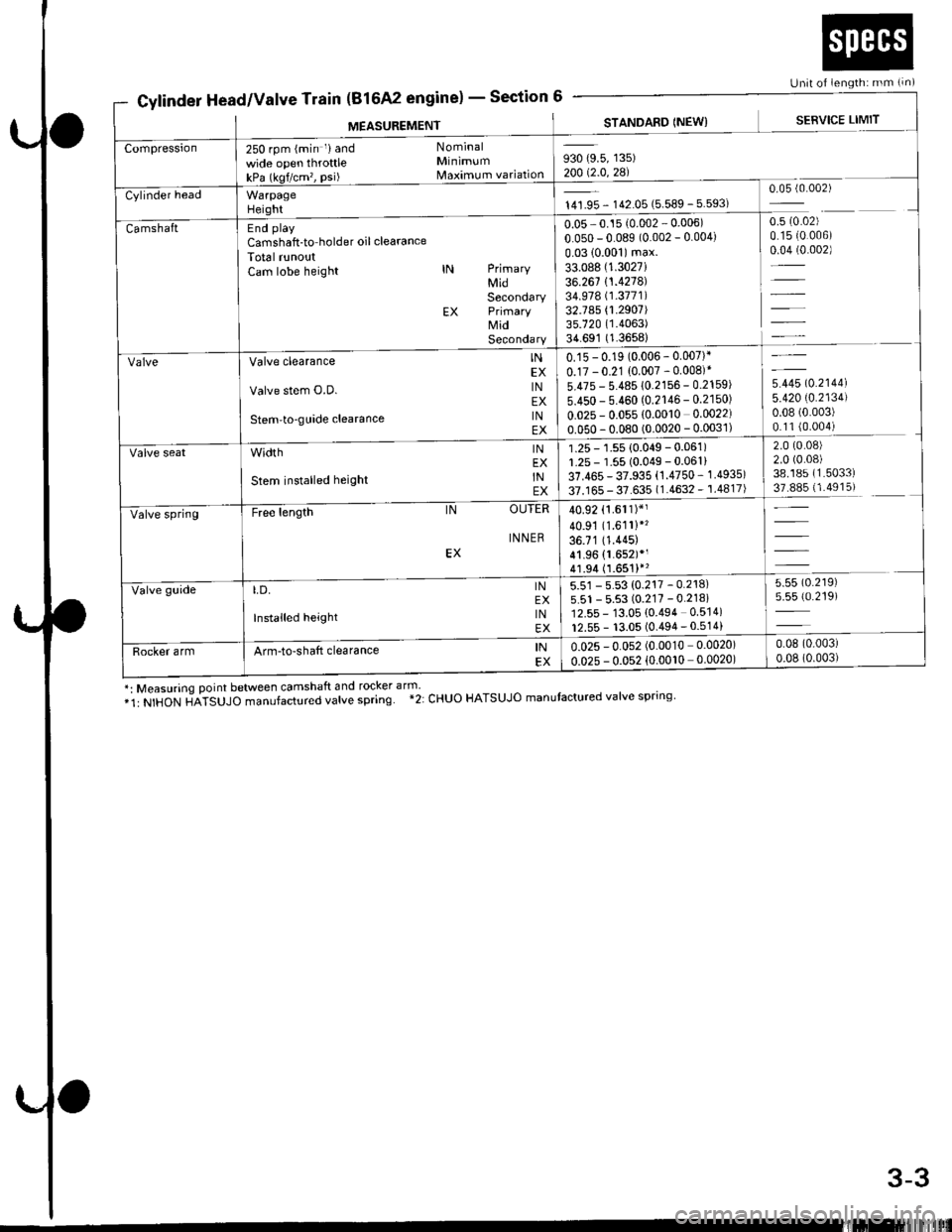
Unit of iength: mm (!n)
930 (9.5, 135)20012.0,zal
0.05 - 0.15 (0.002 - 0.006)
0.050 - 0.089 (0.002 - 0.004)
0.0310.001)max.33.088 (1.3027i
36.261 {1.4278)34.978 (1.3771)
32.785 {1.2907)35.720 (1.4063)
34.691 (1.3658)
u*u lo.r,ool5.420 (0.2134)
0.08 (0.003)
0.11 (0.004)
2.0 (0.08)
2.0 (0.08)
38.185 (1.5033)
37.885 (1.4915)
250 rpm (min riand Nominal
wide open throttle Minimum
kPa (kqf/cm'�, psi) Maximum variation
End play
Camshaft-to holder oil clea€nce
Total runoutCam lobe height lN PrimaryMidSecondaryEX PrimaryMidSecondary
0.15 - 0.19 (0.006 - 0.007)*
0.17 - 0.21 (0.007 - 0.008)*
5.475 - 5.485 10.2156 - 0.2159)
5.450 - 5.460 (0.2146 - 0.2150)
0.025 - 0.055 (0.0010 0.0022)
0.050-0.080 (0.0020 - 0.0031)
Valve clearance
Valve stem O.D.
Stem-to-guide clearance
INEXINEXINEX
1.25 - 1.55 {0.049 - 0.061)r.25 - 1.55 (0.049 - 0.061)
37.465 - 37.935 (1.4750 - 1.4935)
37.165 - 37.635 (1.4632 - 1.4817)
INEXINEX
width
Stem installed height
40.92 (1.611)*'
40.91 (1.6111"
36.71 (1.415)
41.96 (1.652)*r
4 r.94 (1.651)*'
free t*gth lN OUTER
5.51 - 5.53 (0.217 - 0.218)5.51 - 5.53 (0.217 - 0.218i12.55 - 13.05 (0.494 0.5'�j4)
12.55 - 13.05 (0.494 - 0.514)
LD. lNEX
Installed height lNEX
0.025 - 0.052 (0.0010 0.0020)
o.o2s - 0.052 {0.0010 0.0020)
Cylinder Head/Valve Train(816A2 engine) - Section
MEASUREMENTSTANDARD INEW)SERVICE LIMIT
*: Measuring point between camshaft and rocker arm'*1: NTHON H;TSUJO manufactured vatve spring. *2: CHUO HATSUJO manutactured valve spnng.
3-3
Page 49 of 2189
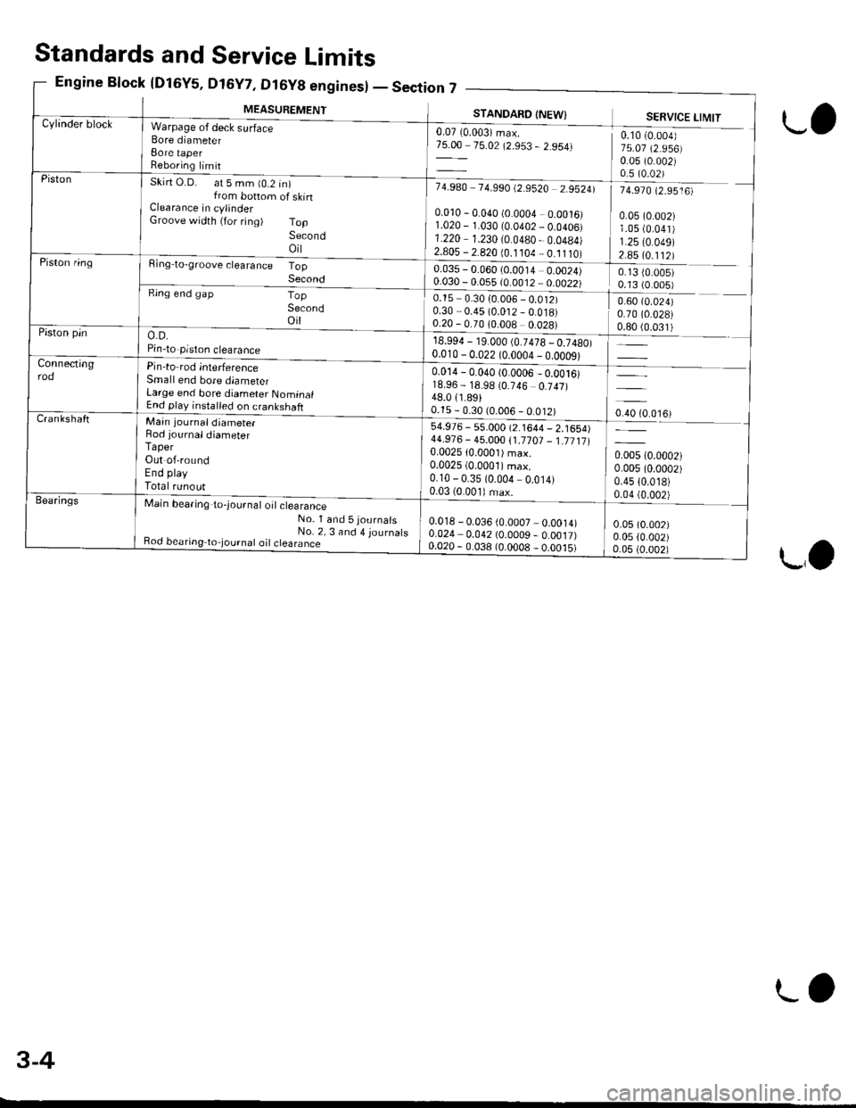
MEASUREMENT
,n7 _--
STANDAFO INEW}
0.07 10.003) max.75.00 75.02 (2.953 - 2.954)
7 4.9A0 7 4.990 t2.9520 2.95241
0.010 - 0.040 (0.0004 0.0016)1.020 - 1.030 10.0402 _ 0.0406)1.220 1.230 (0.0480 - 0.0484)2.805 - 2.820 {0.1 104 _ 0.11 tO)
0.035 - 0.060 (0.0014 0.0024)0.030 - 0.055 {0.0012 0.0022)_
0.15 0.30 {0.006 _ 0.012)0.30 - 0.45 (0.012 - 0.018)0.20 - 0.70 10.008 0.028)
18.994 - 19.000 (0.7478 _ 0.7480)0.010 - 0 0?2 lo oona -n dn^ol
SERVICE LIMIT
0.10 (0.004)
75.07 (2.956)0.05 (0.002)0.5 (0.02)
74.970 (2.9516)
0.05 (0.002)1.05 (0.041)
1.2510.049)2.85 (0.112)
0.13 {0.005)0.13 (0.005)
0.60 (0.024)
0.70 (0.028)
ljqql) _
oro to.o',ur
0.005 (0.0002)
0.005 (0.0002)
0.4510.018)0.04 (0.002)
0.05 (0.002)
0.05 {0.002)0.05 (0.002)
Cylinder blockWarpage of deck surfaceBore diameterBore taperReboring limit
Skirt O.D. at 5 mm (0.2 in)from bottom of skinClearance in cylinderGroove width {for ring) TopSecondoil
Ring to-groove clearance TopSecondRing end gapTopSecondoil
o.D.Pin-to piston clearance
Pin-to rod interferenceSmall end bore diameterLarge end bore diameter NominalEnd play installed on crankshaft
Piston
Piston ring
Piston pin
Connectingrod0.014 - 0.040 (0.0006 _ 0.ool6)18.96 - 18.98 (0.746 0.747)48.011.89)0.15 - 0.30 (0.006 - 0.012)CrankshaftMain journaldiameter
Rod iournaldiameterTaperOut of-roundEnd playTotal runout
Main bearing to-lournal o't clearance-No_ l and 5journals
_ No. 2, 3 and 4 journatsBod bearing to,journat oil ctearance
54.976 - s5.000 (2.1644 - 2.1654)44.91 6 - 45.000 1'1.17 01 _ 1.71 11 10.002510.0001) max.0.0025 (0.0001)max.
0.10 - 0.35 (0.004 0.014)0.03 (0.001) max.Bea.ings
0.018 - 0.036 (0.0007 0.0014)0.024 0.042 (0.0009 - 0.0017)0.020 - 0.038 (0.0008 _ o.oo.t5)
Standards and Service Limits
Engine Block {Dl6Y5, D16Y7, Dt6y8 enginesl - Section
L,
LO
3-4
LO
Page 50 of 2189
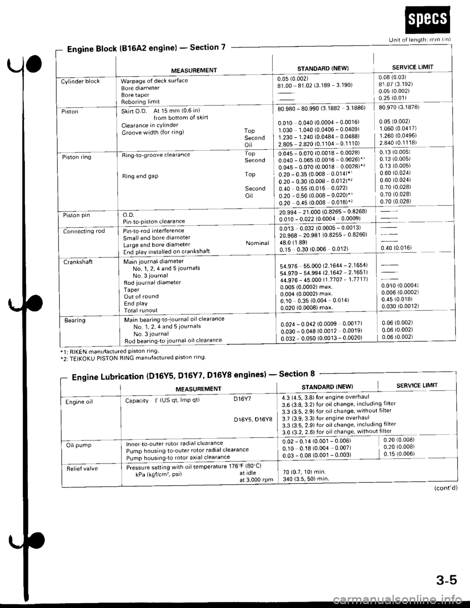
Section 7
Unlt of length: rnm ( n)
Engine Block(816A2 engine) -
MEASUREMENT
Warpage of deck surface
Bore diameterBore taperReboring limit
STANOARD {NEW)
0.05 (0.002)
8L00 81.02 (3.189 3.190)
SERVICE LIMIT
0.08 {0.03)81.07 (3.192)
0.05 (0.002)
0.25 (0.01)
Cylinder block
PistonSkin O D. At 15 mm (0.6 in)
{rom bottom of skirt
Clearance in cylinder
Groove width (for ring) ToPSecondoil
80.980 - 80.990 (3.lUUz 3. rUubl du Y/u lJ. ro/o,
I0.010 0.040 (o.ooo4 - 0.0016' 0 05 r0 002) II O3O 1.040 10.0406 - 0.04091 1 060 {0 0417) |1.230 - 1.?40 {0.0484 . 0.04881 1.260 10.04961 1'*: ?:::i?l:91'::ll:l I::::::= lPiston ringRing-to-groove clearance
Ring end gap
o.D.Pin to-piston clearance
Pin'to rod interference
Small end bore diameter
Large end bore diameterEnd play installed on crankshaft
Main journal diameterNo. 1, 2, 4 and 5 iournalsNo. 3 journal
Rod journal diameterTaperOut of roundEnd play
Total runout
Main bearing to_journal oil clearance
No. 1, 2, 4 and 5 journals
No. 3 journal
Bod bearing'to iournal oil clearance
Second
Top
Secondoil
Nominal
0.13 (0.005)
0.1310.005)0.60 (0.024)
0.60 t0.024)0.7010.028)0.70 (0.028)
,rr]q!4l
-l
u.u45 - u.u/u lu.uu ro
0.040 - 0.065 (0.0016 0.0026)*l
0.045 - 0.070 (0.0018 0.0028)*'
0.20 - 0.35 (0.008 - 0.014)*1
o.20 - 0.30 (0.008 - 0.012)*'�
0.40 0.55 (0.016 0.022)
0.20 - 0.50 (0.008 - 0.020)*'
0.20 - 0.45 (0.008 - 0.018)"
20.994 - 21.000 {0.8265 - 0.8268)
0.010 - 0.022 (0.0004 0.0009)
0.013 - 0.032 (0.0005 - 0.0013)
20.968 20.981 (0.8255 - 0.8260)
lliSlto?,o.oou o.o''r, o.rotoo'ut
Piston pin
Connecting rod
54.976 55.000 (2.1644 - 2.1654)
54.970 - 54.994 (2.1642 2.1651)
44.976 - 45.00011.'1707 - 1.1711|
0.005 (0.0002) max.0.004 (0.0002) max.0.10 0.35 (0.004 - 0.014)
0.020 (0.0008imax.
0.010 (0.0004)
0.006 (0.0002)
0.45 (0.018)
0.030 (0.0012)
Crankshaft
Eearing0.024 - 0.042 (0.0009 0.0017)
o.o3o - 0.048 {0.0012 0.0019)
0.032 - 0.050 (0.0013 - 0.0020)
0.06 (0.002)
0.06 (0.002)
0.06 (0.002)
*1: RIKEN manutactured prston rrng*2:TEIKOKU PISTON RING manufactured piston ring
gineslSection 8
(cont'd)
Engine Lubri,cation (Dl6Y5, Dl5Y7' Dl6Y8 enginesl -
MEASUREMENTSTANOARD (NEW) S€RVICE LIMIT
4.3 (4.5, 3.8)Ior engine overhaul
3.6 (3.8, 3.2) for oil change, including filter
3.3 (3.5, 2.9) for oil change, without filter
3.7 (3.9,3.3)for engine overhaul
3.3 (3.5, 2.9) for oil change, including filter
3.0 {3.2, 2.6} for oil change, without filter
0.02 - 0.14 (O.OO1 - 0.006) 0.20 {0 008)
0.10 0.18 (o.oo4 - 0.007) i 0.20 (0 008)
o 03 !.08 (qool!.oo3l _ (0 006) -
70 (0.7, 10) min.
340 (3.5,50) min
Engine oilCapacity | (US qt, lmp qt) D16Y7
D16Y5 D16Y8
lnner-to-outer rotor radial clearance
Pump housing to_outer rotor radialclearance
Pumo housrnq_to rotor a)rial clearance
Pressure setting with oil temperature 176'F (80'Ci
kPa (kgf/cm'�, PsiI at idleat 3,000 rpm
Oil pump
Relief valve
3-5
Page 51 of 2189
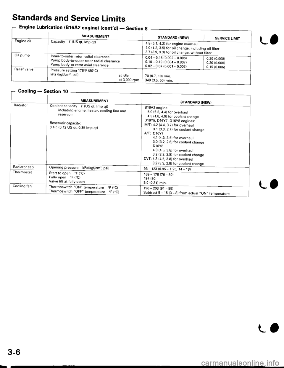
MEASUREMENTSTANDARD INFWIEngine oilCapacityf (uS qt, lmp qt)
Inner-to outer rotor radial clearancePump body-to outer rotor radialclearancePump body to-rotor axial clearance
4.8 (5.1, 4.2) for eng;ne overhaul4.0 (4.2, 3.5) for oil change, ;ncludin3.7 (3.9.3 3)for dil .h,nde '^,irh^,,rg oilfilter
Oil pump0.04 - 0.16 {0.002 - 0.006)0.10 - 0.19 (0.004-0.007)0.02 0.07 10.001 ,0.003)
0.20 (0.008)
0.20 {0.008)0 15 {O OO6iRelief valvePressure setting 176"F (80.C)kPa (kgflcm,, psi) at;dteat 3,000 rpm70 (0.7, 10) min.340 (3.5,50) min.
Standards and Service Limits
Engine Lubrication (B16A2 engine) (cont,d) - Section 8
Cooling - Section 10
L,
L.
MEASUREMENTSTANOARO {NEW)RadratorCoolant capacity t 1US qt, tmp qt)including engine, heater, cooling line andreservotr
Beservoir capacity:0.4 f {0.42 US qt, 0.35 lmp qt)
81642 engine5.0 {5.3, 4.4) for overhaul4.5 (4.8, 4.0) for cootant changeD16Y5, D16Y7, D16Y8 engines:M/T: 4.2 (4.4, 3.7)for overhaul3.1 (3.3, 2.7) for coolant changeA"/T: 016Y74.1 (4.3, 3.6) for overhaul3.0 (3.2, 2.6) for cootant changeDl6Y84.3 {4.5, 3.8)for overhaul3.2 (3.3, 2.8) for cootant changeCW: 4.3 (4.5,3.8)for overhaul3.2 (3.3, 2.8)for cootant chanqeRadiator capOpeningpressure kPa(kgl/cm,,psi)
Start to open .F (.C)Fully open "F ('C)Valve lift at fulty open
93 123 (0.95- 1.25, 14 18)
169 - 176 (76 80)194 (90)
8.0 (0.31)min.
196 - 203 191 95)Subtract 5 - 15 {3 - 8) from actual ,,ON,, temperature
Thermostat
Cooling fanThermoswilch 'ON" temperature F r.C,Thermoswitch "OFF' lemperature .F ( C)
L
3-6
L,