page 1 HONDA CIVIC 1996 6.G Workshop Manual
[x] Cancel search | Manufacturer: HONDA, Model Year: 1996, Model line: CIVIC, Model: HONDA CIVIC 1996 6.GPages: 2189, PDF Size: 69.39 MB
Page 2 of 2189
INTRODUCTION
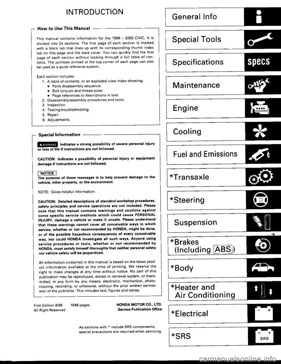
How to Use This Manual
This manual contains information for the 1996 - 2000 ClVlC. lt is
divided into 24 sections. The first page of each section is marked
with a black tab that lines up with its corresponding thumb index
tab on this page and the back cover. You can quicklY find the first
page of each section without looking through a tull table ol con_
tents. The symbols printed at the top corner of each page can also
be used as a quick reference system.
Each section includesl
1. A table of contents, or an exploded view index showing:
. Parts disassemblY sequence.
. Bolt torques and thread sizes.
. Page references to descriptaons in text
2. Disassembly/assembly procedures and tools.
3. Inspection.
4. Testing/troubleshooting.
5. Repair.
6. Adjustments.
Special Information
!@ Indicates a sttong possibility of sover. perconal iniurY
or loss ol lite if in3tructions are not follow€d.
GAUTION: Indicaiqs a possibility ot p€lsonal injury or 6quipm.nt
damage il instiuc'tions are not followod
t Noncali-. pu.po.. ot thes6 messages is to help provent demage lo lhe
vehicle, other property, or the €nvironment.
NOTE: Gives helpful information.
CAUTfON: Detaifed descriptions ol standard workshop p.oceduro3.
safoty principles and servico operations are not included. Pleaso
note that this manual contain3 wetnings and cautions against
some sp6cific sGrvic€ methods which could cause PERSONAL
INJURY, damage a vohicle or make il unsafe. Ploase undorstand
that these warnings cannot covsr all conceivable weys in which
service. whelher or not iocommgndod bY HONDA. mighi bo done,
or ol tho possiblG hazardou3 consgquonces of ev€aY conceivablg
way, nor could HONDA invqstigato all 3uch way3. AnYono using
sgrvice procedures or lools, whethei or nol rGcommendod bY
HONDA, must srtisty hifisetf thoroughlylhat nohher pefsonal sefety
nor vehiclc satsty will be reopardi2ed.
All intormation contained in this manual is based on the latest prod
uct information available at the time oI printing We reserve the
right to make changes at any time without notice No part of this
publication may be reproduced, stored in retrieval system, or trans'
mitted, in any form by any means, electronic, mechanical, photo
copying, recording, or otherwise, without the prior written permis-
sion of the publisher. This includes text, figures and tables.
*Transaxle
ds
First Edition 8/99 1848 PagesAll Right Reserved
HONOA MOTOR CO., LTD.
Sorvico Publication Offico
As sections with * include SRS components;
sDecial precautions are lequired when servlclng
*Electrical't
*SRSSRS
Page 47 of 2189
(urbY5, ul6Y7, Dl6Yg enl
MEASUREMENT
Sines) -Section6 -
STANDARD INFWTCompression250 rpm and wide open throftlekPa {kgf/cm,, psi) NominalMinimumMaximum variationWarpageHeight
End play
Camshaft to-holder oil clearanceTotal runoutCam lobe height D16y7
D16Y5
D16Y8
INEXIN
EXIN
EX
Secondary
PrimaryMidSecondary
930 {9.5, 135)200 12 0 ?R\Cylinder head
92.95 - 93.05 {3.659 3.663)0.05 {0.002)
Camshaft0.05,0.15 (0.002 0.006)0.050 - 0.089 (0.002 _ o.oo4)0.03 (0.001)max.
35.299 (1.3897131.241 /.1.4678)38.427 (1.5129)32.193 11 .267 4l38.784 (1.5269)
36.778 (1.4479)
38.274 (1.5068)
37.065 .4592)38.008 (1.4964)
0.5 (0.02)
0.15 (0.006)
0.04 (0.002)
=
Valve clearanca {Cold)
Valve stem O.D.
Stem-to guide clearance
width
Stem insta ed height
Free lengrh Dt6y7D16Y5
INEXINEXINEX
INEXINEX
INEXINEX
INEXINEX
D16Y8
t.D.
Installed height
0.18 - 0.22 10.007 - 0.009)0.23 0.27 (0.009 0.011)5.48 - 5.49 (0.2157 0.2161)5.45 - 5.46 {0.2146 _ 0.2150}0.02 - 0.05 (0.001 _ o.oo2)0.05-008lono2-nnn?l
5.45 (0.2146)
5.42 tO.213410.08 (0.003)
0.11 (0.004)
1.6 (0.063)
2.0 (0.079)
53.a9 \2.122|j$.a9 Q.122)
Valve seat0.85 - 1.15 (0.033 - 0.045)1.25 - 1.55 10.049 - 0.061i53.17 - 53.64 {2.093 _ 2.112)53.17 - 53.64 (2.093 _ 2.112)Valve spring57 .9 (2.2a)
56.5 \2.22157 .9 t2.29l58.0 (2.2a)
58.7 {2.31iValve guide5.51 - 5.53 (0.217 - 0.218)5.51 - 5.53 (0.217 _ 0.218)17.85 - 18.35 \0.103 - 0.722)18.65 19. t5 (0.734 _ 0.754)
5.55 t0.219)5.5s {0.219)
Rocker armArm-to shaft clearanceINEX0.017 - 0.050 (0.0007 0.0020)0.018 - 0.054 (0.0007 - 0.0021)0.08 (0.003)
0.08 (0.003)
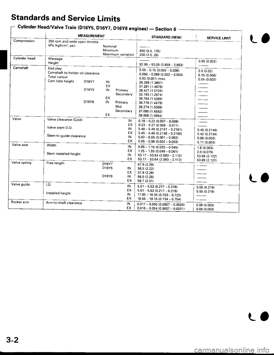
Standards and Service Limits
Cylinder Head/Valve Train (Dt6y5, Dt6y7, D
L,
ra
3-2
LO
Page 49 of 2189
MEASUREMENT
,n7 _--
STANDAFO INEW}
0.07 10.003) max.75.00 75.02 (2.953 - 2.954)
7 4.9A0 7 4.990 t2.9520 2.95241
0.010 - 0.040 (0.0004 0.0016)1.020 - 1.030 10.0402 _ 0.0406)1.220 1.230 (0.0480 - 0.0484)2.805 - 2.820 {0.1 104 _ 0.11 tO)
0.035 - 0.060 (0.0014 0.0024)0.030 - 0.055 {0.0012 0.0022)_
0.15 0.30 {0.006 _ 0.012)0.30 - 0.45 (0.012 - 0.018)0.20 - 0.70 10.008 0.028)
18.994 - 19.000 (0.7478 _ 0.7480)0.010 - 0 0?2 lo oona -n dn^ol
SERVICE LIMIT
0.10 (0.004)
75.07 (2.956)0.05 (0.002)0.5 (0.02)
74.970 (2.9516)
0.05 (0.002)1.05 (0.041)
1.2510.049)2.85 (0.112)
0.13 {0.005)0.13 (0.005)
0.60 (0.024)
0.70 (0.028)
ljqql) _
oro to.o',ur
0.005 (0.0002)
0.005 (0.0002)
0.4510.018)0.04 (0.002)
0.05 (0.002)
0.05 {0.002)0.05 (0.002)
Cylinder blockWarpage of deck surfaceBore diameterBore taperReboring limit
Skirt O.D. at 5 mm (0.2 in)from bottom of skinClearance in cylinderGroove width {for ring) TopSecondoil
Ring to-groove clearance TopSecondRing end gapTopSecondoil
o.D.Pin-to piston clearance
Pin-to rod interferenceSmall end bore diameterLarge end bore diameter NominalEnd play installed on crankshaft
Piston
Piston ring
Piston pin
Connectingrod0.014 - 0.040 (0.0006 _ 0.ool6)18.96 - 18.98 (0.746 0.747)48.011.89)0.15 - 0.30 (0.006 - 0.012)CrankshaftMain journaldiameter
Rod iournaldiameterTaperOut of-roundEnd playTotal runout
Main bearing to-lournal o't clearance-No_ l and 5journals
_ No. 2, 3 and 4 journatsBod bearing to,journat oil ctearance
54.976 - s5.000 (2.1644 - 2.1654)44.91 6 - 45.000 1'1.17 01 _ 1.71 11 10.002510.0001) max.0.0025 (0.0001)max.
0.10 - 0.35 (0.004 0.014)0.03 (0.001) max.Bea.ings
0.018 - 0.036 (0.0007 0.0014)0.024 0.042 (0.0009 - 0.0017)0.020 - 0.038 (0.0008 _ o.oo.t5)
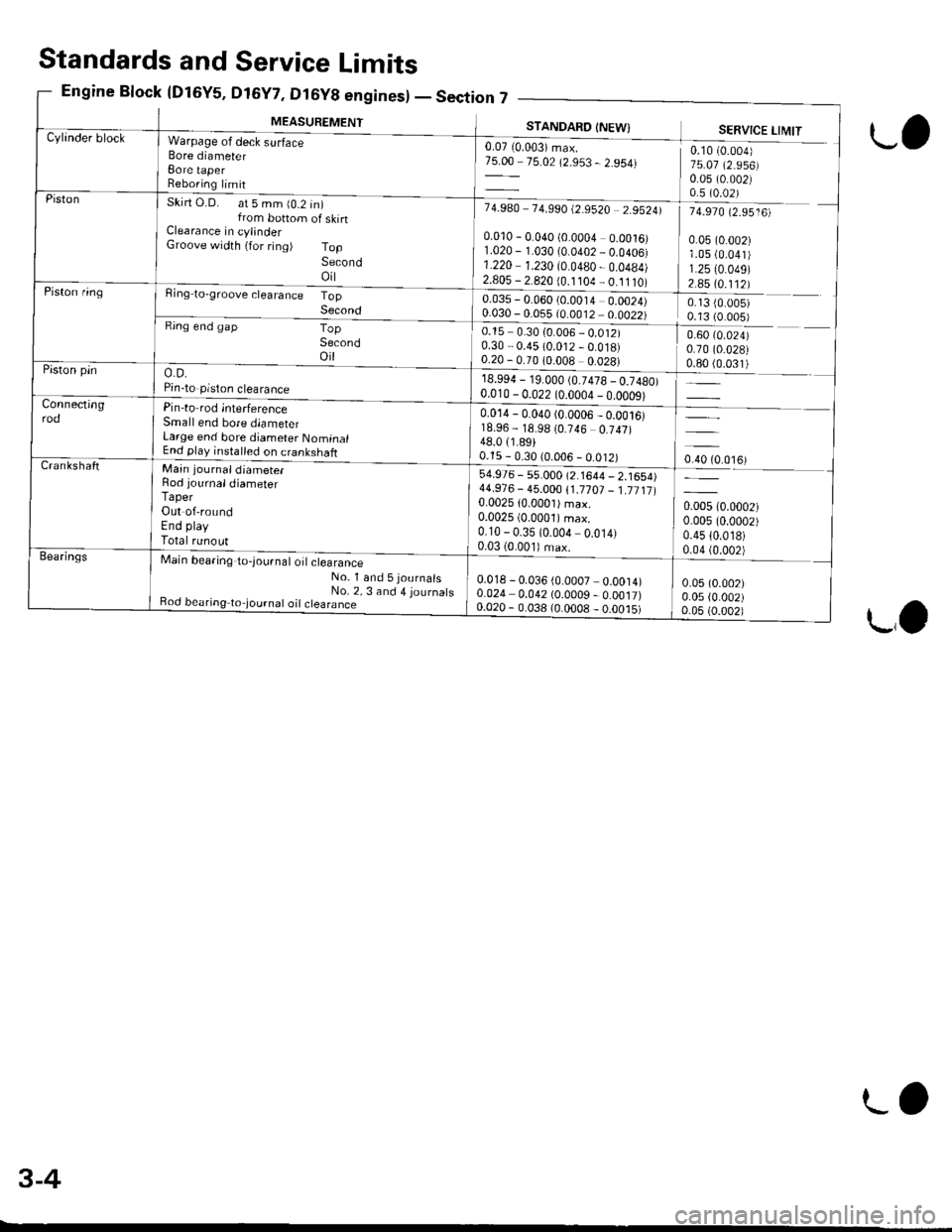
Standards and Service Limits
Engine Block {Dl6Y5, D16Y7, Dt6y8 enginesl - Section
L,
LO
3-4
LO
Page 50 of 2189
Section 7
Unlt of length: rnm ( n)
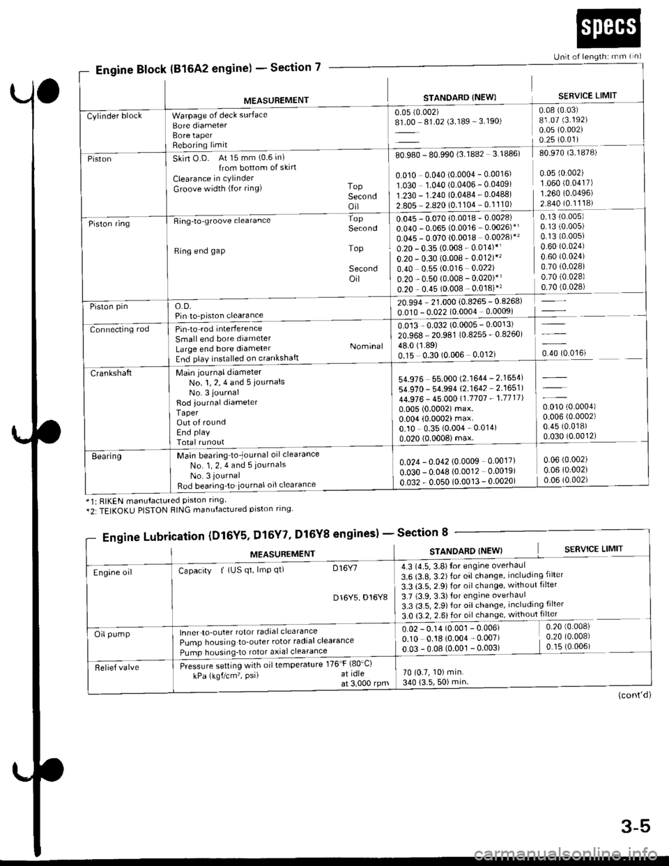
Engine Block(816A2 engine) -
MEASUREMENT
Warpage of deck surface
Bore diameterBore taperReboring limit
STANOARD {NEW)
0.05 (0.002)
8L00 81.02 (3.189 3.190)
SERVICE LIMIT
0.08 {0.03)81.07 (3.192)
0.05 (0.002)
0.25 (0.01)
Cylinder block
PistonSkin O D. At 15 mm (0.6 in)
{rom bottom of skirt
Clearance in cylinder
Groove width (for ring) ToPSecondoil
80.980 - 80.990 (3.lUUz 3. rUubl du Y/u lJ. ro/o,
I0.010 0.040 (o.ooo4 - 0.0016' 0 05 r0 002) II O3O 1.040 10.0406 - 0.04091 1 060 {0 0417) |1.230 - 1.?40 {0.0484 . 0.04881 1.260 10.04961 1'*: ?:::i?l:91'::ll:l I::::::= lPiston ringRing-to-groove clearance
Ring end gap
o.D.Pin to-piston clearance
Pin'to rod interference
Small end bore diameter
Large end bore diameterEnd play installed on crankshaft
Main journal diameterNo. 1, 2, 4 and 5 iournalsNo. 3 journal
Rod journal diameterTaperOut of roundEnd play
Total runout
Main bearing to_journal oil clearance
No. 1, 2, 4 and 5 journals
No. 3 journal
Bod bearing'to iournal oil clearance
Second
Top
Secondoil
Nominal
0.13 (0.005)
0.1310.005)0.60 (0.024)
0.60 t0.024)0.7010.028)0.70 (0.028)
,rr]q!4l
-l
u.u45 - u.u/u lu.uu ro
0.040 - 0.065 (0.0016 0.0026)*l
0.045 - 0.070 (0.0018 0.0028)*'
0.20 - 0.35 (0.008 - 0.014)*1
o.20 - 0.30 (0.008 - 0.012)*'�
0.40 0.55 (0.016 0.022)
0.20 - 0.50 (0.008 - 0.020)*'
0.20 - 0.45 (0.008 - 0.018)"
20.994 - 21.000 {0.8265 - 0.8268)
0.010 - 0.022 (0.0004 0.0009)
0.013 - 0.032 (0.0005 - 0.0013)
20.968 20.981 (0.8255 - 0.8260)
lliSlto?,o.oou o.o''r, o.rotoo'ut
Piston pin
Connecting rod
54.976 55.000 (2.1644 - 2.1654)
54.970 - 54.994 (2.1642 2.1651)
44.976 - 45.00011.'1707 - 1.1711|
0.005 (0.0002) max.0.004 (0.0002) max.0.10 0.35 (0.004 - 0.014)
0.020 (0.0008imax.
0.010 (0.0004)
0.006 (0.0002)
0.45 (0.018)
0.030 (0.0012)
Crankshaft
Eearing0.024 - 0.042 (0.0009 0.0017)
o.o3o - 0.048 {0.0012 0.0019)
0.032 - 0.050 (0.0013 - 0.0020)
0.06 (0.002)
0.06 (0.002)
0.06 (0.002)
*1: RIKEN manutactured prston rrng*2:TEIKOKU PISTON RING manufactured piston ring
gineslSection 8
(cont'd)
Engine Lubri,cation (Dl6Y5, Dl5Y7' Dl6Y8 enginesl -
MEASUREMENTSTANOARD (NEW) S€RVICE LIMIT
4.3 (4.5, 3.8)Ior engine overhaul
3.6 (3.8, 3.2) for oil change, including filter
3.3 (3.5, 2.9) for oil change, without filter
3.7 (3.9,3.3)for engine overhaul
3.3 (3.5, 2.9) for oil change, including filter
3.0 {3.2, 2.6} for oil change, without filter
0.02 - 0.14 (O.OO1 - 0.006) 0.20 {0 008)
0.10 0.18 (o.oo4 - 0.007) i 0.20 (0 008)
o 03 !.08 (qool!.oo3l _ (0 006) -
70 (0.7, 10) min.
340 (3.5,50) min
Engine oilCapacity | (US qt, lmp qt) D16Y7
D16Y5 D16Y8
lnner-to-outer rotor radial clearance
Pump housing to_outer rotor radialclearance
Pumo housrnq_to rotor a)rial clearance
Pressure setting with oil temperature 176'F (80'Ci
kPa (kgf/cm'�, PsiI at idleat 3,000 rpm
Oil pump
Relief valve
3-5
Page 52 of 2189
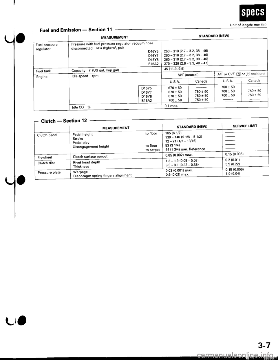
Unit of length: mm (in)
Fuel and Emission - Section
MEASUREMENTSTANOARO (NEW)
260 310 (2.7 - 3.2, 38 - 46)
260 - 310 (2.7 - 3.2, 38 - 46i
260 - 310 (2.7 - 3.2, 38 - 46)
210 - 320 Q.A - 3.3, 40 - 47 1
45 {11.9, 9.9)
M/T (neutral) I A/T or C\.T (lE or fd positioni
Fuel paessure
regulator
Pressure wilh fuel pressure regulator vacuum hose
disconnected kPa (kgvcm'�, Psi)D16Y5D 16Y7D16Y881642
FueltankCapacity I (US gal, lmp gal)
E ngineldle speed rpm
016Y5D16Y7D16Y8816A2
u.s.A.CanadaU,S,A.Canada
670 1 506701 50670150700 t 50
7501 507501 507501 50
700 t 50700 I 507001 50750150750 r 50
ldle CO %0.1 max.
Clutch - Serrtion 12
MEASUREMENTSTANDARD {NEWI I SERVICE LIMIT
Clutch pedalPedal height to floor
StrokePedal play
Disengagement height to floorto carpet
16s (6 1/2)130 140 (5 1/8 5 1/2)
12 -21 t1l2 - 13/16183 (3 1/4)44 (1 3/4) min. Reference
FlywheelClutch surface ruoout
Rivet head depthThickness
0.05 (0.002) max.0.15 (0.006)
Clutch disc1.3- 1.9 (0.05 - 0.07)
8.5 - 9.1 (0.33 - 0.36)
0.2 {0.01)5.5 (0.22)
Pressure plateWarpageDiaphragm spring fingers alignment
0.03 (0.001) max0.6 (0.02) max
0.15 (0.006)
1.0 (0.04)
Lro
3-7
lfllHlllllllllrltllli[
Page 101 of 2189
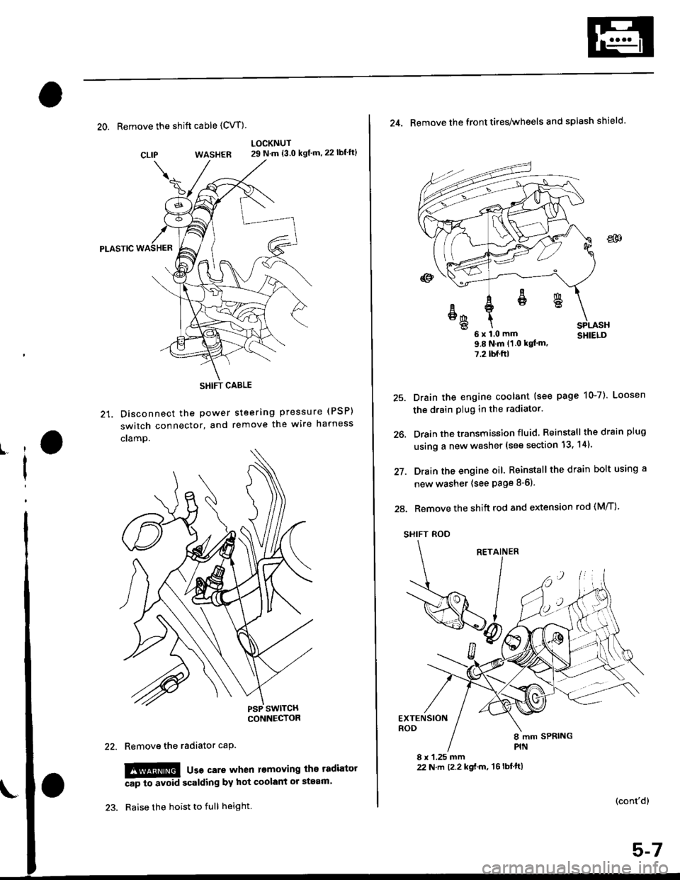
20. Remove the shift cable (CVT)
WASHER
Pt-Aslc
21. Disconnect the Power
switch connector, and
cramp.
LOCKNUT29 N.m {3.0 kgf m,22lbf'ft}
steering pressure (PSP)
remove the wire harness
CLIP
ll
I
Remove the radiator caP.
!!!@ usa care when l€moving the tadiator
Ap to avoid scalding by hot coolant or steam'
Raise the hoist to full height.
SHIFT CABLE
(cont'd)
25.
26.
27.
24. Remove the front tires/wheels and splash shield.
u x l.u mm SHIELD9.8Nm(1 0 kqt'm,
7.2lbf.ftl
Drain the engine coolant (see page 10-7). Loosen
the drain plug in the radiator.
Drain the transmission fluid Reinstall thedrainplug
using a new washer (see section 13, 14).
Drain the engine oil. Reinstall the drain bolt using a
new washer (see page 8-6).
28. Remove the shift rod and extension rod (M/T)
SHIFT ROD
EXTENSIONROD
8 x 1.25 mm22 N.m t2.2 kgf'm, 't6lbtft)
ER
6x1.0mm
Page 110 of 2189
Engine Removal/lnstallation
Installation (cont'd)
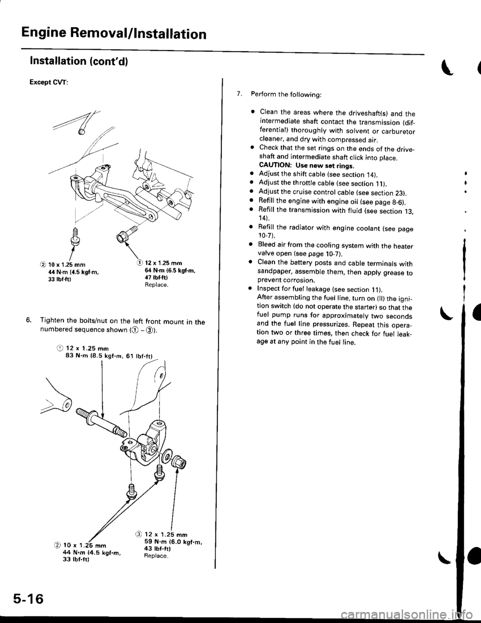
Except CVT:
12 x 1.25 mm64 N.m (6.5 kgd.m,
Tighten the bolts/nut on the left front mount in thenumbered sequence shown {O - @).
(t 12 x 1.25 mm83 N'm (8.5 kgf.m,61 tbt.trl
/+4 N.m 14.5 kgf.m,33 lbt.trl
O 12 r 1.25 mm59 N.m 16.0 kgt.m,43 tbt.rtlSeplace.
5-16
\
7. Perform the following:
. Clean the areas where the driveshaft(s) and theintermediate shaft contact the transmission (dif_ferential) thoroughly with solvent or carburetorcteaner, and dry with compressed air.. Check that the set rings on the ends of the drive_shaft and intermediate shaft click into place.CAUTION: Use new set rings,. Adjust the shift cable (see section 14).. Adjust the throttle cable (see section 11).. Adjust the cruise control cable (see section 23).. Refill the engine with engine oil (see page 8-6).. Refill the transmission with fluid (see section 13,14).
. Refill the radiator with engine coolant (see page10-7).
. Bleed air from the cooling system with the heatervalve open (see page j0-7).
. Clean the battery posts and cable terminals withsandpaper, assemble them, then apply grease toprevent corrosaon.. Inspect for fuel leakage (see section j l).After assembling the fuel line, turn on l) the igni_tion switch (do not operate the starter) so that thefuel pump runs for approximately two secondsand the fuel line pressurizes. Repeat this opera_taon two or three times, then check for fuel leak_age at any point in the fuel line,
Page 112 of 2189
Cylinder Head/Valve Train
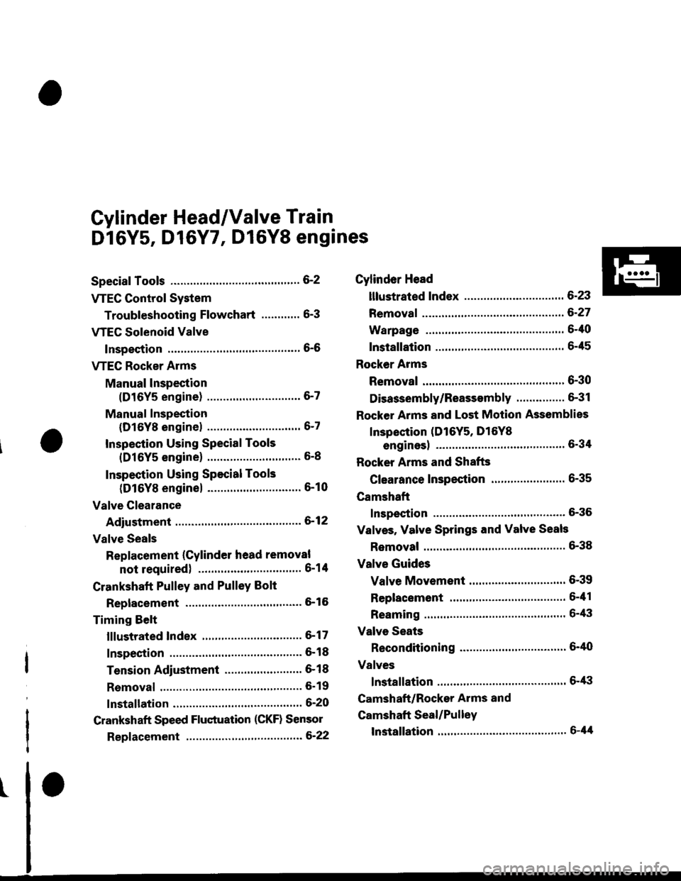
Dl6Y5, D16Y7, Dl6Y8 engines
Special Tools ............. G2
VTEC Control System
Troubleshooting Flowchart .........." 6-3
VTEG Solenoid Valve
Inspection ............" 6-6
VTEC Rocker Arms
Manual lnspection
(D16Y5 engine) ............................. 6-7
Manual Inspection
(D16Yg enginel ................'............ 6-7
Inspection Using Special Tools
{D16Y5 engine} .....................""'... 6-8
Inspection Using Special Tools
(D16Y8 engine) .........................'.'. 6-10
Valve Clearance
Adiustment ..."".....6-12
Valve Seals
Replacement (Cylinder head removal
not requiredl ................................ 6-1tl
Crankshaft Pulley and PulleY Bolt
Replacement ."...... &16
Timing Selt
lllustrated Index ............................... 6-17
Inspection .............. 6-18
Tension Adjustment ........................ 6- 1 I
Removal ......,,......... 6-19
lnstallation ............. 6-20
Crankshaft Speed Fluctuation (CKF) Sensor
Repf acement .........6'22
Cylinder Head
lllustrated Index ............................... 6-23
Removal ................. 6-27
Warpage ................ 6-40
lnstallation ............. 6-45
Rocker Arms
Removal ................. 6-30
Disassembly/Reassambly ............... 6-31
Rocker Arms and Lost Motion Assemblies
Inspection (D16Y5, D16Yg
enginesl "..........' 5-34
Rocker Arms and Shafts
Glearance Inspection ....................... 6-35
Camshaft
Inspection .............. 6-36
Valves, Valve Springs and Valve Seals
Removal ........""..... 6-38
Valve Guides
Valve Movement .............................. 6-39
Replacement .........6-41
Reaming .......'......'.' 6-43
Valve Seats
Reconditioning .'....6'40
Valves
lnstallation ............. 6-tt3
Camshaft/Rocker Arms and
Camshaft Seal/Pulley
lnstallation ............. 6-44
Page 114 of 2189
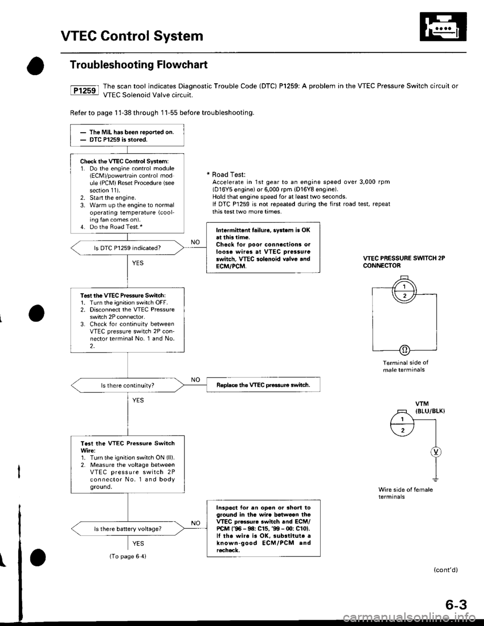
VTEC Control System
Troubleshooting Flowchart
tFtrsrl #ilH:::lj1t:"J:T,?ffnostic
rrouble code (Drc) Pr25e: A probrem in the vrEc Pressure switch circuit or
Reter to page 1 l-38 th roug h 1 1-55 before trou bleshooting.
* Road Test:Accelerate in 1st gear to an engine speed over 3,000 rpm(D16Y5 engine) or 6,000 rpm (D'16Y8 engine).Hold that engine speed for at least two seconds.It DTC P1259 is not repeated during the first road test, repeatthis test two more tames.
VTEC PRESSURE SWITCH 2PCONNECTOR
Terminal side ofmale terminals
Wire sid6 ol femalerermtnats
VTM
l1 (BLu/BLK)
f;-) |I
I
Y
I
The MIL has been reoorted on.DTC P1259 is sto.ed.
Check the VTEC Cont.ol Syst6m:1. Do the engine control module(ECM)/powertrain control module lPCM) Reset Procedure (see
section 11).2. Stan the engine.3. Warm up the engine to normaloperating temperature (cool-
ing fan comes on).4. Do the Boad Test.*Intermittont tailura, 3y3t.m is OKat thia time.Check for ooor connoctionr o.loose wirea at VTEC oiassurclwitch, VTEC solonoid valvo .ndECM/PCM,
ls OTC P1259 indicated?
Test rhe VTEC Prensure Switch:1. Turn the ignition switch OFF.2. Disconnect the VTEC Pressureswitch 2P connector.3. Check for continuity betweenVTEC pressure switch 2P con-nector terminal No. 1 and No.2.
Replace the VTEC preasure 3witch.ls there continuity?
Te3t the VTEC Pressure SwitchWire:1. Turn the ignition switch ON lll).2. Measure the voltage betweenVTEC press u re switch 2Pconnector No. l and bodyground.
In3poct for en opon or shod toground in thG wi.. bctwoon thoVTEC pro$ur6 switch rnd ECM/PCM l'96 - 9a: C15,'99 - 00: C101.lf tha wiro i3 OK,3ubrtitute aknown-good ECM/PCM andrecheck.
ls there battery voltage?
{To page 6'4i
Page 115 of 2189
I
VTEC Control System
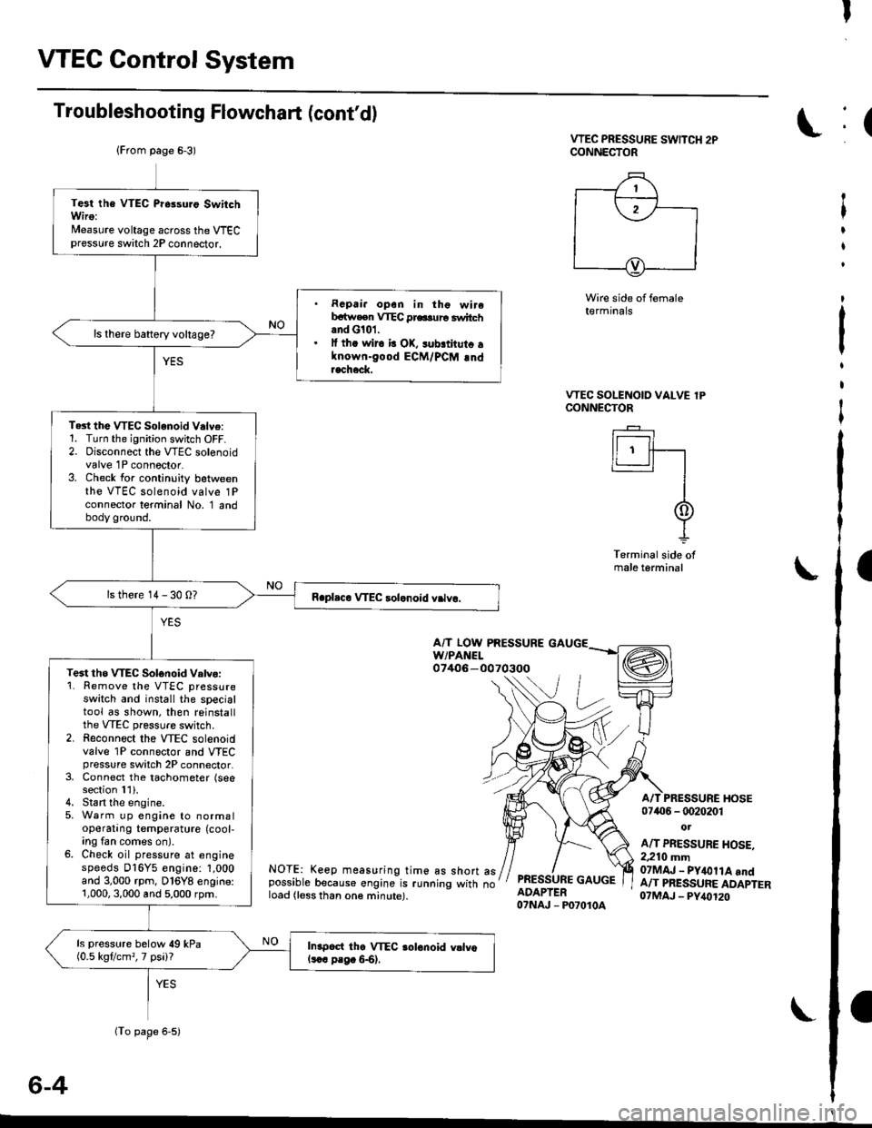
Troubleshooting Flowchart (cont'd)
VTEC PRESSURE SwlTCH 2PCONNECTOR
Wire side of female(€rmrnats
VTEC SOLENOID VALVE lPCONNECTOR
I r----'t I
ll ' ff---r'�-'�1
I
I
-L
Terminal side ofmale terminal
A/T LOW PRESSUREw/PAt{EL07406-0070300
NOTE: Keep measuring time as short aspossible because engine is running with noload (less than one minute).
PRESSURE GAUGEADAPTER07NAJ - P07010A
A/T PRESSURE I{OSE07406 - 0020201
ot
A/T PRESSURE HOSE.2,210 mm07MAJ - PY&llA andA/T PRESSURE ADAPTER07MAJ - PY,()120
6-4
(From page 6-3)
(To page 6-5)
Test the VTEC Pr6suro SwitchWiro:Nleasure voltage across the VTECpressure switch 2P connector.
. Rcpai. opon in tho wirebrtw.en VTEC pr6.urc switchand G101.. lf th. wir6 b OK, sub.thuto alnown-good ECM/PCM !ndracheck.
ls there baftery voltage?
Te3t the VTEC Solonoid V.lve:1. Turn the ignition switch OFF.2. Disconnect the VTEC solenoidvalve 1P connector.3. Check for continuity betweenthe VTEC solenoid valve 1Pconnector terminal No. 1 andbody ground.
ls there 14 - 30 0?
Te3t tho WEC Solonoid Vatvo:'1. Remove the VTEC pressureswatch and install the specialtool as shown, then reinstallthe VTEC pressure switch.2. Reconnoct the VTEC solenoidvalve 1P connector and VTECpressure switch 2P connector.3, Connect the tachometer (seesection 11).4. Stan the engine.5, Warm up engine to normaloperating temperature (cool,ing fan comes on).6. Check oil pressure at enginespeeds D16Y5 engine: 1,000and 3.000 rpm, D16Y8 engine:1,000,3,000 and 5,000 rpm.
ls pressure below 49 kPa(0.5 kgflcm,, 7 psi)?In.poct the VTEC aolonoid vllvols.c p.g. &6).
:(
t
I
t
:
t
I
I