Index HONDA CIVIC 1997 6.G User Guide
[x] Cancel search | Manufacturer: HONDA, Model Year: 1997, Model line: CIVIC, Model: HONDA CIVIC 1997 6.GPages: 2189, PDF Size: 69.39 MB
Page 200 of 2189
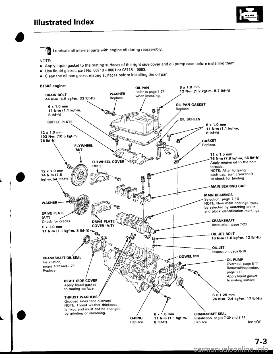
lllustrated Index
I runricate att internal parts with engine oil during reassembly'
NOTE:
o Apply liquid gaskettothe mating surfaces ofthe right side cover and oil pumpcase before installingthem'
. Use liquid gasket, part No 08718-0001 or08718-0003'
. Clean the oil pan gasket mating surfaces betore installing the oil pan
81642 engine:
DRAIN BOLT44 N,m {4.5 kgf'm,33 lbt'ft)
6 x 1.0 mm'11 N.m (1.1 kgI'm,
I tbl.ft)
OIL PANReter to page 7 27when installing.
6 r 1.O mm12 N.m t1.2 kgl'm, 8 7 lbf'lt)
OIL PAN GASKET
BUFFLE PLA
12 x 1.0 mm103 N.m {10.5 kgf'm,
76 tbr.ft)
6 x 1.0 mm11 N.m (1 .1 kgf.m,
8 tbI.fr)
GASKETReplace.FLYWHEEL(M/TI
12 x 1.0 mm
74 N.m (7.5
kof.m, 54 lbf'ft)
1^c{Eb\%^ t*^
*o"rr^--(Wffi
oa*,trto2,.w
FLYWHEEL COVER
IM/T)
DRIVE PLATECOVER (AiT)
11 x 1.5 mm76 N.m (7.9 kgf'm, 56 lbf'ft)
Apply engine oil to the bolt
threads.NOTE: After torqurngeach cap, turn crankshaft
to check for binding.
MAIN EEARING CAP
MAIN BEARINGSSelection, page 7_10
NOTE: New main bearings musl
be selected bY matching crank
and block identification markrngs
CRANKSHAFTInstallation, Page 7'23
OIL JET BOLT16 N.m 11.6 kgf'm, 12 lbl'ft)
OIL JETInspection, Page 8_10
Check for cracks
6x1.0mm11 N.m {1.1 kgf'm, I lbf'ft}
CRANKSHAFT OIL SEAL
Installation,pagesl 22 andl 29
Replace-
DOWEL PINOIL PUMPOverhaul, page 8-'l1Removal/lnspection,page 8-13.Apply liquid gasket
to mating surlace.RIGHT SIDE COVERApply liquid gasket
to mating surface.
THRUST WASHERS8 x 1.25 mm24 N.m {2.4 kgf.m, 17 lbf'ft)Grooved sides face outward
NOTE: Thrusr washer thickness
is tixed and must not be changed
by grinding or shimming
O-RINGReplace
CRANKSHAFT SEAL11 N.m {1.1 kgf'm, lnstallation, pages 7'29 and I 14
a lbt.ltl Heplace. (cont'd)
d#*
Page 201 of 2189
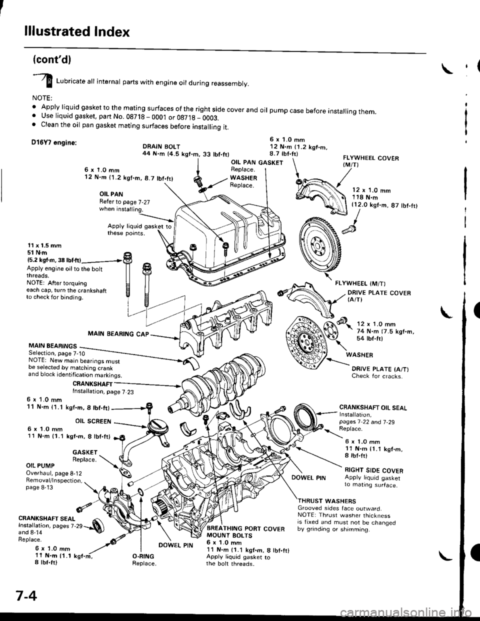
lllustrated Index
(cont'dl
I Luoricate att internal parts with engine oil during reassembly.
NOTE:
' Apply liquid gasket to the mating surfaces ofthe rightside coverand oil pumpcase before installingthem.. Use liquid gasket, part No. 08718 - 0001 or 087,18 _ OOO3.. Clean the oil pan gasket mating surfaces before installing it.
D16Y7 engine:6 x 1.0 mm12 N.m (1.2 kgt.m.8.7 tbf.tr)DRAIN BOLT44 N.m {4.5 kgt.m.33 tbt.ttl
,(
I
I
OIL PAN GASKETFLYWHEEL COVERIM/T)6x 1.0 mm12 N.m ('l .2 kgt.m, 8.7 tbt.trl
OIL PANRefer to page 7-27
Apply liquid gasker tothese points.
Replace.
WASHERReplace.12 x '1.0 mm118 N.m{12.0 kgt.m, 87 tbf.tr}
11 x 1.5 mm51 N.m15.2 kgl.m,38lbtftl
Apply engine oilto the boltthreads.NOTE: After torquingeach cap, turn the crankshaftto check for binding.
MAIN BEARINGSSelection, page 7-10
MAIN BEARING CAP
CRANKSHAFTInstallation, page 7 23
NOTE: New main bearings mustbe selected by matching crankand block identification markings.
6 r 1.0 mm11 N.m {1.1
6 x 1.0 mm11 N.m 11.1
ksI.m, 8 lbt.ft)
OIL SCREEN
kgt.m, 8 lbf.trl
Check for cracks.
CRANKSHAFT OIL SEALInstallation,pages 1 22 a^d 7-29
\:eprace'
GASKETReplace.
6 x 1.O mm11 N.m {1.1 kgt.m,8 rbt.frl
RIGHT SIDE COVERApply liquid gasker1o matrng surface,
OIL PUMPOverhaul, page 8-12Bemoval/lnspection,page 8-13
DOWEL PIN
WASHERSGrooved sides face outward.NOTE: Thrust washer thicknessis fixed and must not be changedby grinding or shimming.
CRANKSHAFT SEAL
l.j"Ji:l"^ pages z.2e --.S)
Replace.
6 x 1.0 mm11 N.m {1.18 tbt.fr)
7-4
BREATHING PORT COVERMOUNT BOLTS6 x 1.0 mm11 N.m {1.1 kgt.m, 8 tbf.fr}Apply liquid gasker tothe boh threads.
DOWEL PIN
Page 203 of 2189
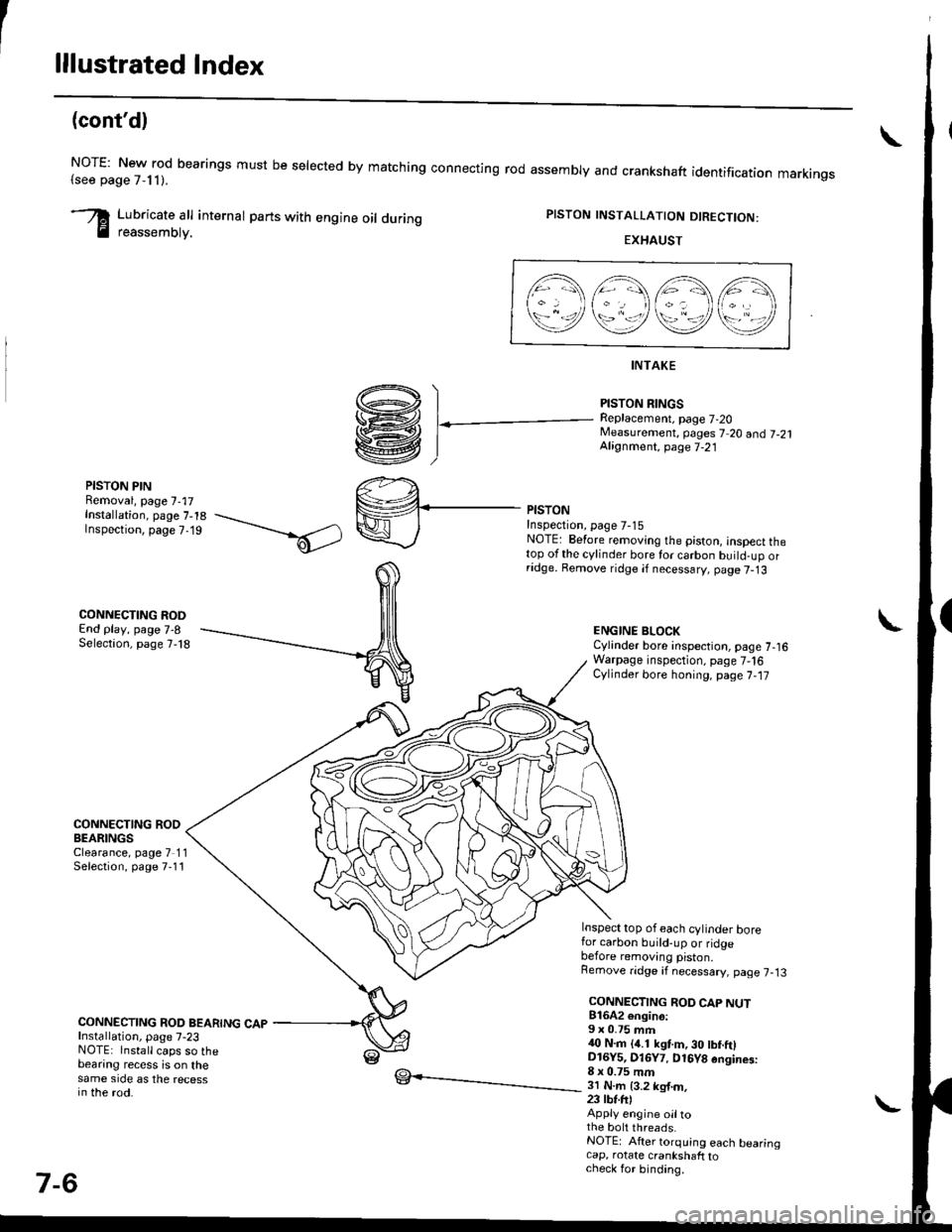
lllustrated Index
(cont'd)
NOTE: New rod bearings must be selected by matching connecting rod assembly and crankshaft(see page 7,11).identification markings
Lubricate all internal parts with engine oil duringreassembtv.
PISTON INSTALLATION DIRECTION:
EXHAUST
4\/=\6\z\
\e/!rqrf/
INTAKE
PISTON RINGSReplacement. page 7-20Measurement, pages 7 20 andj-21Alignment, page 7-21
PISTON PINRemoval, page 7,17Installation, page 7-18Inspection, page 7,19
CONNECTING RODEnd play, page 7-8Selection, page 7,18
CONNECTING RODBEARINGSClearance, page 7 11Selection, page 7-11
CONNECTING ROD BEARING CAPInstallation, page 7-23NOTE: lnstall caps so thebearing recess is on thesame side as the recessin the rod.
PISTONInspectron, page 7-15NOTE: Betore removing the piston, inspect thetop of the cylinder bore for carbon build-up orridge. Bemove ridge if necessary, page 7-13
ENGINE BLOCKCylinder bore inspection, page 7-16Warpage inspection, page 7,'16Cylinder bore honing, page 7,17
Inspect top of each cylinder borefor carbon build-up or ridgebefore removing piston.Remove ridge if necessary, page 7-13
CONNECTING ROD CAP NUT816A2 €ngin6:9 x 0.75 mm{0 N.m (4.1 kgt m, 30 tbf.ftlD16Y5, Dl6Y7. D16Y8 engines:8 x 0.75 mm3l N.m {3.2 kg{.m,23 tbt.fr)Apply engine oiltothe bolt threads.NOTE: After torquing each bearingcap, rotate crankshaft tocheck for binding.
7-6
Page 227 of 2189
Engine Lubrication
SpecialTools .......... "'.""".8'2
lllustrated Index ........... .'..' 8-3
Engine Oil
Inspection .....'......"....."'. 8-6
Replacement........'......".'.'..."...."......" 8-7
OilFilter
Rep1acement...............".'...'..'.....'.'...". 8-8
Oil Pressure
Testing '.....' 8-9
OilJet (B16A2 engine)
Inspection ...'.'......"...."'..8-10
OilPump
overhaul.'... .....'...'..'."""' 8-11
Removal/lnspection/lnstallation ..'.... 8-1 3
Page 229 of 2189
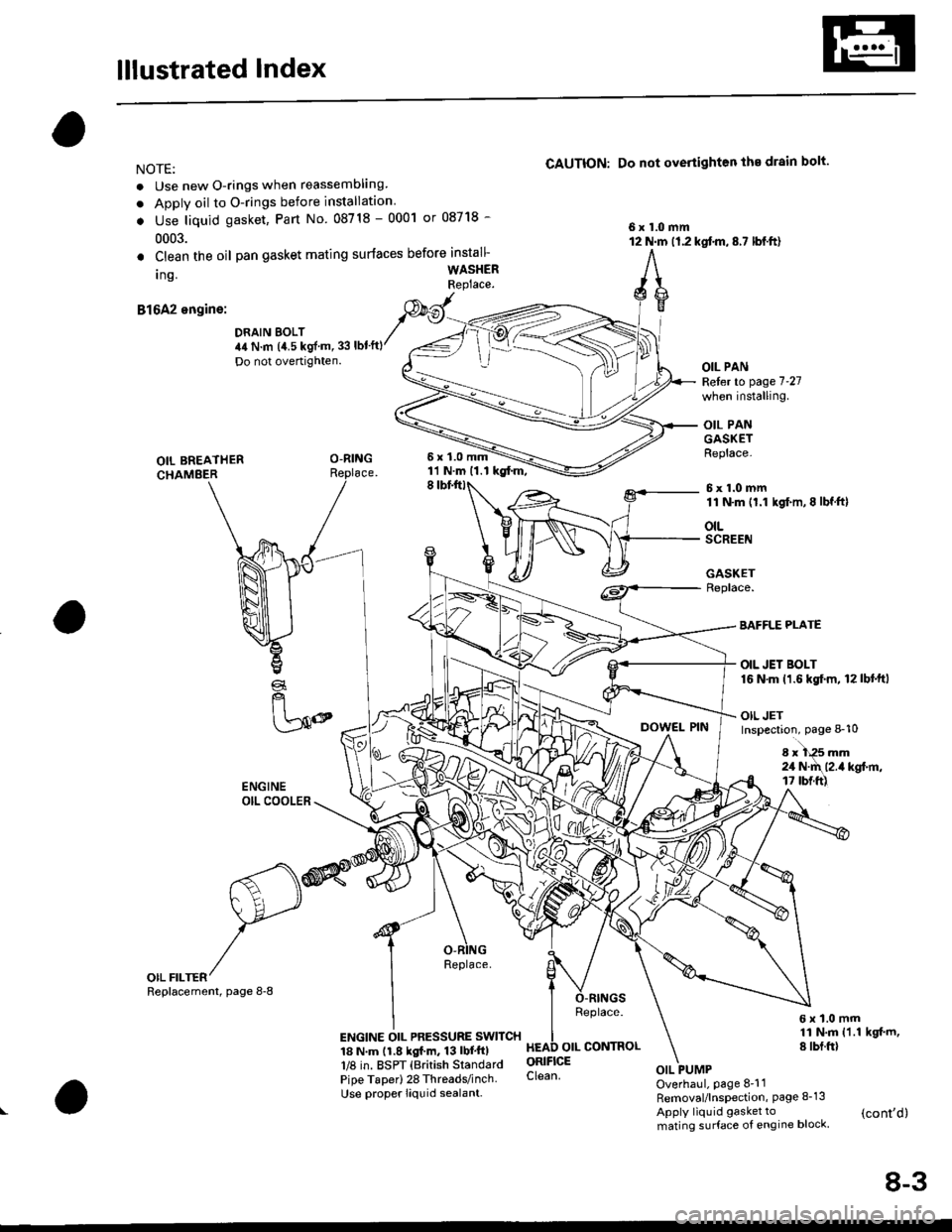
lllustrated Index
NOTE:
. Use new O-rings when reassembling
. Apply oil to O-rings before installation
. Use liquid gasket, Part No 08718 - 0001 or 08718 -
0003.
CAUTION: Do not overiighten the drain bolt.
6x1.0mm12 N.m (1.2 kqtm,8.7 lbl.ftl. Clean the oil
Ing.
B1642 engine:
pan gasket mating surlaces before install-
WASHERRePlace'
DRAIN BOLT44 N.m (4.5 kgl'm,33 lbt'ft)
Do not overtrghten.
6x1.0mm11 N.m (1.1 kgtm,
OIL PANReler to page 7'27
when installing.
OIL PANGASKETReplace-
6x1.0mm11 N'm (1.1 kgl.m,8 lbf.ft)
OIL BREATHERCHAMEER8
otLSCREEN
GASKETReplace.
€!
fl
[50
BAFFLE PLATE
OIL JET BOLT16 N'm 11.6 kgf.m, 12lbt'ttl
OIL JETInspection, page 8-10
8x1+5mm24 N.d\l2.il kgf.ft,t7 tbtft)
OIL FILTERReplace.
ENGINE OIL PRESSURE SWITCH
Pipe Taper) 28 Threads/inch Clean
Use proper liquid sealant.
6x1.0mm11 N.m 11.1 kgt m,8 tbt.frl
Overhaul. page 8'11Removal/lnspection, Page 8-13
Apply liquid gasket to (cont,d)mating surface of engine block
Replacemenl, page 8-8
Replace.
8-3
Page 230 of 2189
lllustrated Index
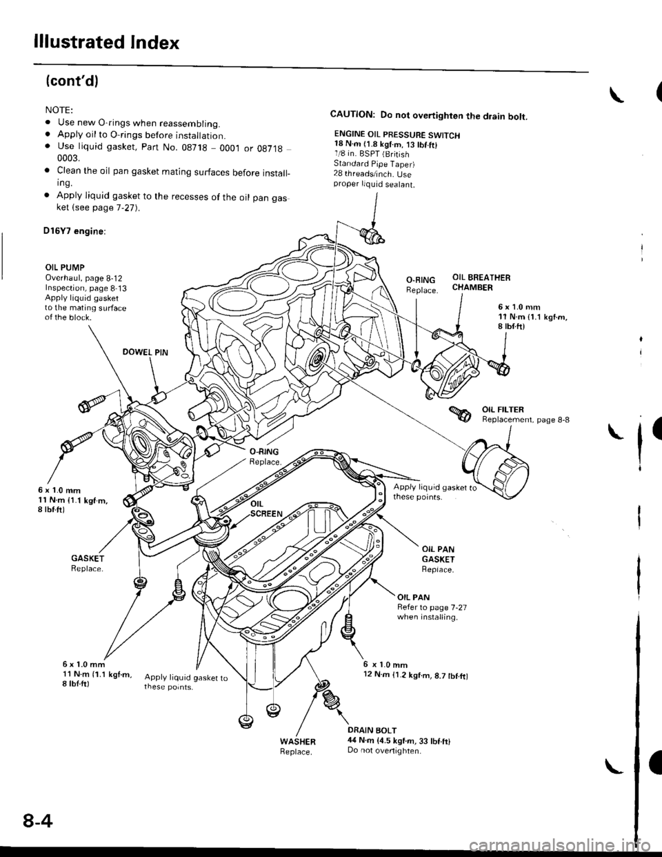
(cont'dl
NOTE:
. Use new O-rings when reassembling.. Apply oil to O-rings before instaltal|on.. Use liquid gasket, Part No. 08718 0001 or 0e7190003.
. Clean the oil pan gasket mating surfaces before install_ing.
. Apply liquid gasket to the recesses of the oil pan gasket (see page 7-27).
D16Y7 €ngine:
OIL PUMPOverhaul, page 8-12Inspection, page 8 13Apply liquid gaskerto the mating surfaceof the block.
DOWEL PIN
CAUTION: Do not overtighten the drain bolt.
ENGINE OIL PBESSURE SWITCH18 N.m (1.8 kgtm, 13 tbt.trl1/8 in. BSPT (BritishStandard Pipe Taper)28 threads/inch. Useproper liquid sealant.
O-BINGReplace.
OIL BREATHERCHAMBER
6x1.0mm'11 N.m { 1.1 ksnm,8 tbtft)
6x1.0mm1l N.m {1.1 kgf-m,8 tbf.ftl
ll
OIL PANGASKETBepiace.
OIL PANRefer to page 7-27when installing.
6x1.0mm11 N m (1.1 kgt.m,8 tbl.ftlApply liquid gasket to
6 x 1.0 mml2 N.m {1.2 kgtm, 8.7 tbf.ft)
DRAIN BOLT44 N.m {4.5 kgtm, 33 tbf.ft}Do not ovenighten.
a
8-4
Page 256 of 2189
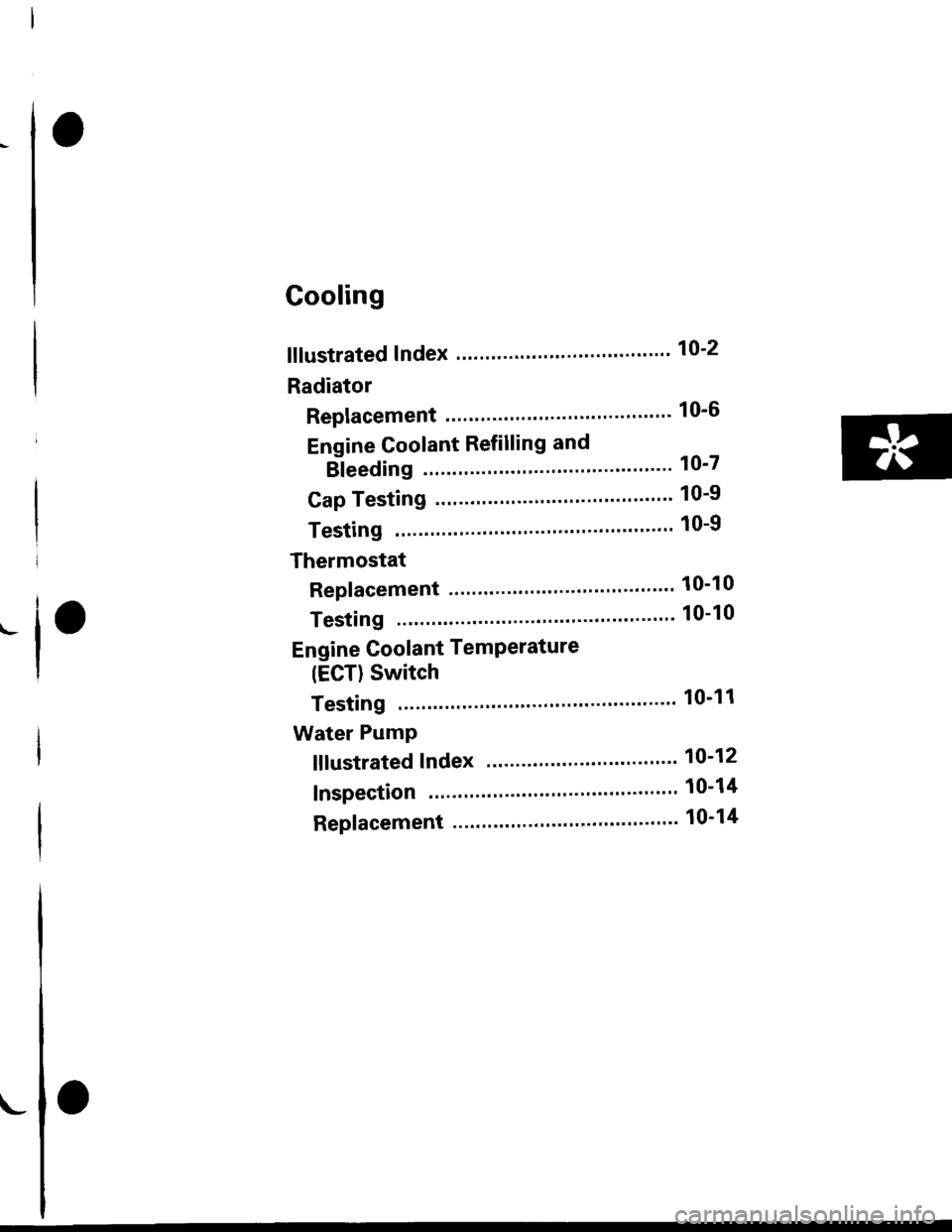
Cooling
fllustrated Index ."..."... ""' 10-2
Radiator
Replacement .'....'...."..."
Engine Coolant Refilling and
Bleeding
Cap Testing
Testing
Thermostat
Replacement .............'....
Testing
10-6
10-7
10-9
10-9
10-10
10-10
Engine Goolant TemPerature
(ECT) Switch
Testing """ 10-11
Water PumP
fffustrated Index ......'... " 10-12
Inspection ' 10'14
Replacement ..'..'...."...'.'....'..'.....'.""" 10-14
!
Page 257 of 2189
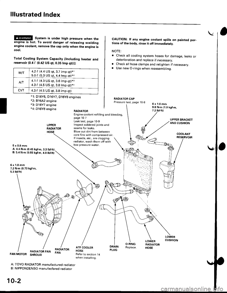
lllustrated Index
@@ system is under high pressure when theengine is hot. To avoid dangsr of rsleasing scaldingengine coolant, removo the cap only when the engine iscoot.
Total Cooling System Capacity flncluding heater andfoservoir (0.4 f (0.42 US qt, 0.35 tmp qt)ll:
*2: 81642 engine*3: D16Y7 engine*4: D16Y8 engine
CAUTION: lf any engine coolant spills on painted por-tions of the body, rinse it off immediately.
NOTE:
. Check all cooling system hoses for damage, leaks ordeterioration and replace if necessary.. Check all hose clamps and retighten if necessary.. Use new O-rings when reassembling.
RADIATOR CAPPressure test, page '10 86x1.0mm9.8 N.m {1.0 kgtm,7.2 tbt.ltl
UPPERRADIATORHOSE
UPPER BRACKETAND CUSHION
COOLANT
RAOIATOREngine coolant refilling and bleeding,page 10 7Leak test, page 10-9Inspect soldered joints andseams for leaks,Blow out dirt Irom betweencore fins with compressed air.lf insects, etc,, are cloggingradiator, wash them off withrow pressure water.
RESERVOIR
5x0.8mmA: ,1.4 N.m {0.45 kgf.m, 3.3 tbtftlg: 5.4 N.m (0.55 kgtm.4.0 tbf.ft)
6x1.0mm7.2 N.m (0.73 kgt.m,5.3 tbtftl
LOWERCUSHION
RADIATOR FANBADIATORFAN
DRAINPLUG
O-RINGReplace.
LOWEBRADIATORHOSE
FAN MOTOR SHROUD
Ar TOYO RADIATOR manufactured radiatorB: NIPPONDENSO manufacfared raoraror
10-2
Refer to section 14when installing.
Mt-|-4.2 f (4.4 US qt,3.7 tmp qt)*j
5.0 / (5.3 U$ q1, 4.4 16p q11*z
4.1 f (4.3 US qt, 3.6 lmp q0*3
4.31 (4.5 US qt, 3.8 tmp qt)*a
CVT4.3 f (4.5 US qt,3.8 Imp qt)
*1i D16Y5, D16Y7, D16Y8 engines
iil
Page 259 of 2189
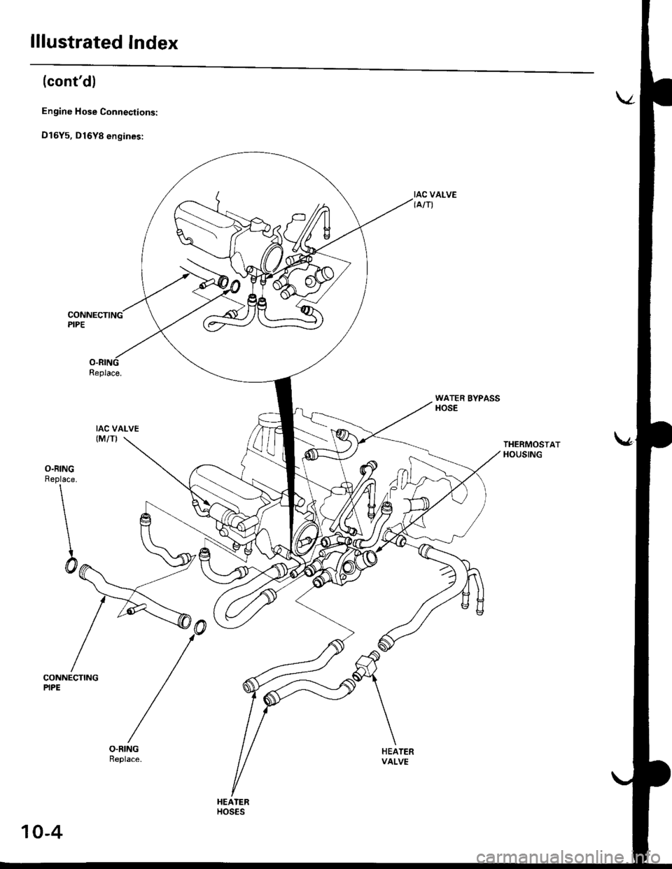
lllustrated Index
(cont'd)
Engine Hose Connections:
D16Y5, D16Y8 engines:
Replace.
IAC VALVE(M/TI
IAC VALVE{A/T)
WATER BYPASSHOSE
THERMOSTATHOUSING
O.RINGReplace.
\
\
\
\h
CONNECTINGPIPE
HEATERVALVE
HEATERHOS€S
10-4
Page 267 of 2189
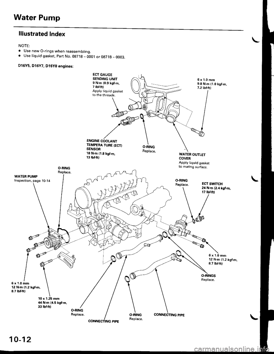
Water Pump
lllustrated Index
NOTE:
. Use new O-rings when reassembrrng.. Use liquid gasket, Part No. 08718 - 0OOl or 087 t8 _ 0003.
O16Y5, D16Y7, D16Y8 engines:
ECT GAUGESENDING UNIT9 N.m {0.9 kgI.m,7 tbnftlApply liquid gasketto the threads.
ENGINE COOLANTTEMPERA TURE (ECT)SENSOR1E N.m (1,8 kgf.m,13 rbttt)
6x 1.0 mm9.8 N.m {1.0 kgf.m,7.2 tbt.ft'|
O.RINGReplace.WATER OUTLETCOVERApply liquid gasketto mating surface.
ECT SW1TCH24 N.m 12.4 kgf.m,17 rbf.ftl
6xl.0mm12 N.m {1.2 kgf.m,8.7 tbf.ft)
6x1.0mm'12 N.m {1.2 kgt m,8.7 lbt fr)
10 x 1.25 mmitl N.m 14.5 kgt m,33 rbf.ftlO.RINGReplace.
10-12