Code 38 HONDA CIVIC 1997 6.G Workshop Manual
[x] Cancel search | Manufacturer: HONDA, Model Year: 1997, Model line: CIVIC, Model: HONDA CIVIC 1997 6.GPages: 2189, PDF Size: 69.39 MB
Page 1863 of 2189
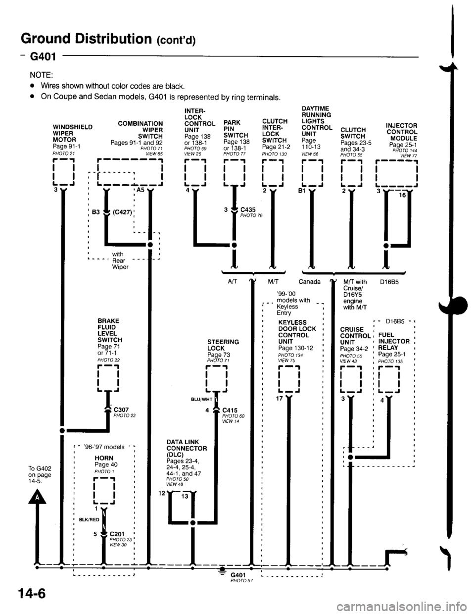
Ground Distributioh (conrd)
)
- G401
NOTE:
To G402on page14-5.
WINOSHIELOWIPERMOTORPage 91-1
DAYTIMERUNNINGLIGHTS
99.!rRoL cLUrcHuNr I swtTcH:?99^ Pases 23-5and 34-3vtEw 66 PHA|A 55
I
I
INJECTORCONTROLMODULEPage 25-1
I
I
3
. Wires shown without color codes are black.
o On Coupe and Sedan models, G401 is represented by ring terminals.
tl
tl
INTER.LOCK6611p99 PARKUN|T PINpaoe j38 SWITCHor ige_t Page 138PHoro6s of 138-1vtEw 26 PHOfO /7r-1 r-'t
tttl
CLUTCHINTER-LOCKSWITCHPage 21-2
ll
ll
ttl
rll
I
Itttl
'Ll;
I
n
t
M/T with 01685Cruise/D16Y5enginewith M/T
BRAKEFLUIDLEVELswtTcHPage 71ot 71-1
tl
tl
DOOR LOCK .CONTROLSTEERINGLOCKPage /3
tl
tl
UNITPage 130-12 ;
ttl
tt:
models
RNte 40
I
I
(
I
I czor
l'i1l?,
'97 mo
HORNPage 4
I
I
NFnl
s 9c.Plv'
BLK/RED
t
IJ;--
',f-l
DATA LINKCONNECTOR(DLC)Pages 23-4,24-4,25 4,44-1, and 47
30
14-6
G401
Page 1865 of 2189
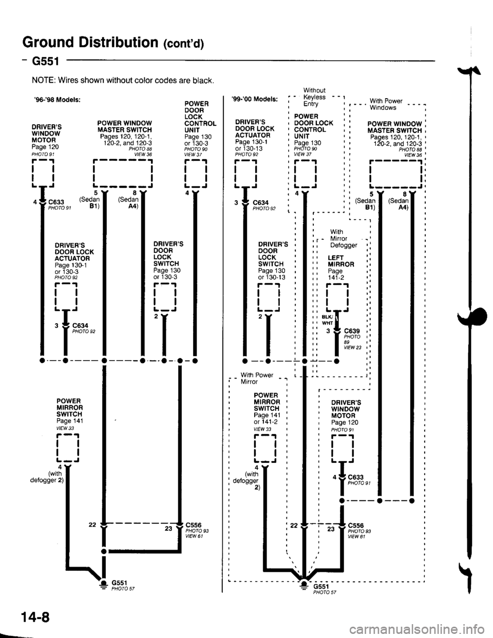
Ground Distribution (cont'd)
1
- G551
Page
I
I
'96-'98 Models:
DRIVER'SwtNDowMOTOR
NOTE: Wires shown without color codes are black.
4
12091
I
I
c633
oRrvER'sDOOR LOCKACTUATORPage 130-1or 130-3
tl
tl
:f ;'*"
.--a ----
sl)
POWER WINDOWMASTER SWITCHPages 120, 120-1,120-2, and 120-3PHO|O AAvlEW 36
tl
tlL-----J
POWERDOORLOCKCONTROLUNITPage 130or 130-3
vlEW3/
tl
tl
4
c556
vtEw 61
8(SedanA4)
DRIVER'SDOORLOCKswrTcHPage 130or 130-3
tl
tl
,I
'-.o -.o -
POWERMIRRORswrTcHPage 141vlEw 33
ll
tl
4(withdefogger 2)
G55t
14-8
Page 1866 of 2189
_t
89c559
Wrth. - - MilrorFUEL , DetoggerTANKUNIT ' RIGHTpaoes 74 ; POWERanj sr -r , MIBRORPHofo 103 | Page 141-2
i-l : i-l
I ltl I
,,:l'it{;
FUELTANKFUEL INTERNALPUMP SOLENOIDPaqe 23-1 VALVEor1q: Page 25-1PHOTO 103 PHOTO 145
r-.| r-'r
tttl
tttlL-J L-J'l
:l'a,t,
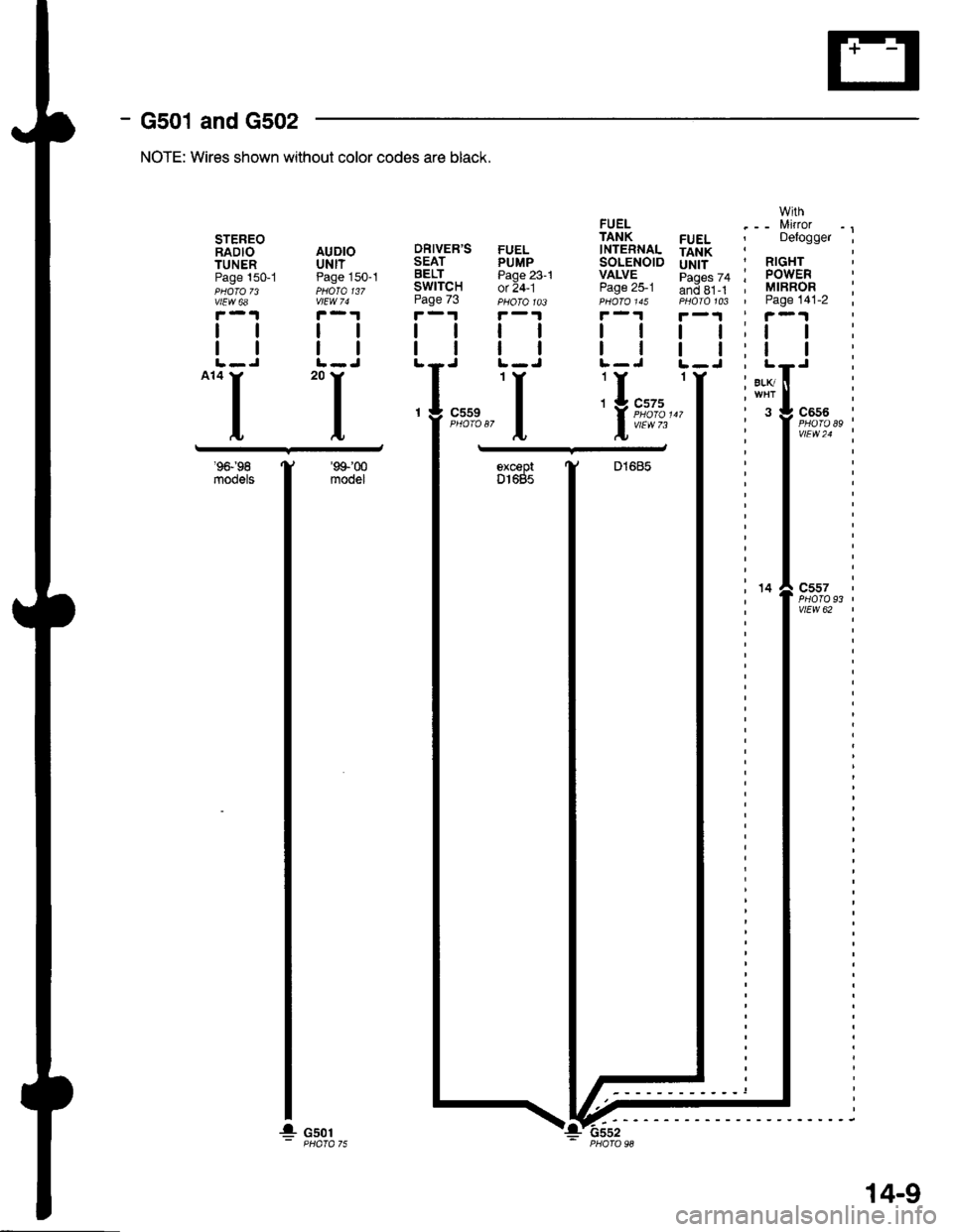
- G501 and G502
'9&'98
m@els
NOTE: Wires shown without color codes are black.
DRIVER'SSEATBELTSWITCHPage 73
tl
tl
STEREORADIO AUDIOTUNER UNITPage 150-1 Page 150-1PHOTO 73 PHOTO 137vtEw 6a vlEw 74
F-.|F-.1
ttll
trtlL-J L-J-.I 'I
93'c557
vtEW 62
'99'00
modelexceprDl685
14
G501
14-9
!-6ssz
Page 1867 of 2189
l
RIGHTOUTERBRAKE LIGHT/TAIL LIGHTPages 110-3and 110-15
(l
RIGHTREARTURNSIGNALLIGIITPage 110-7
l-
LEFTREARTURNSIGNALLIGHTPage 110-7
l-
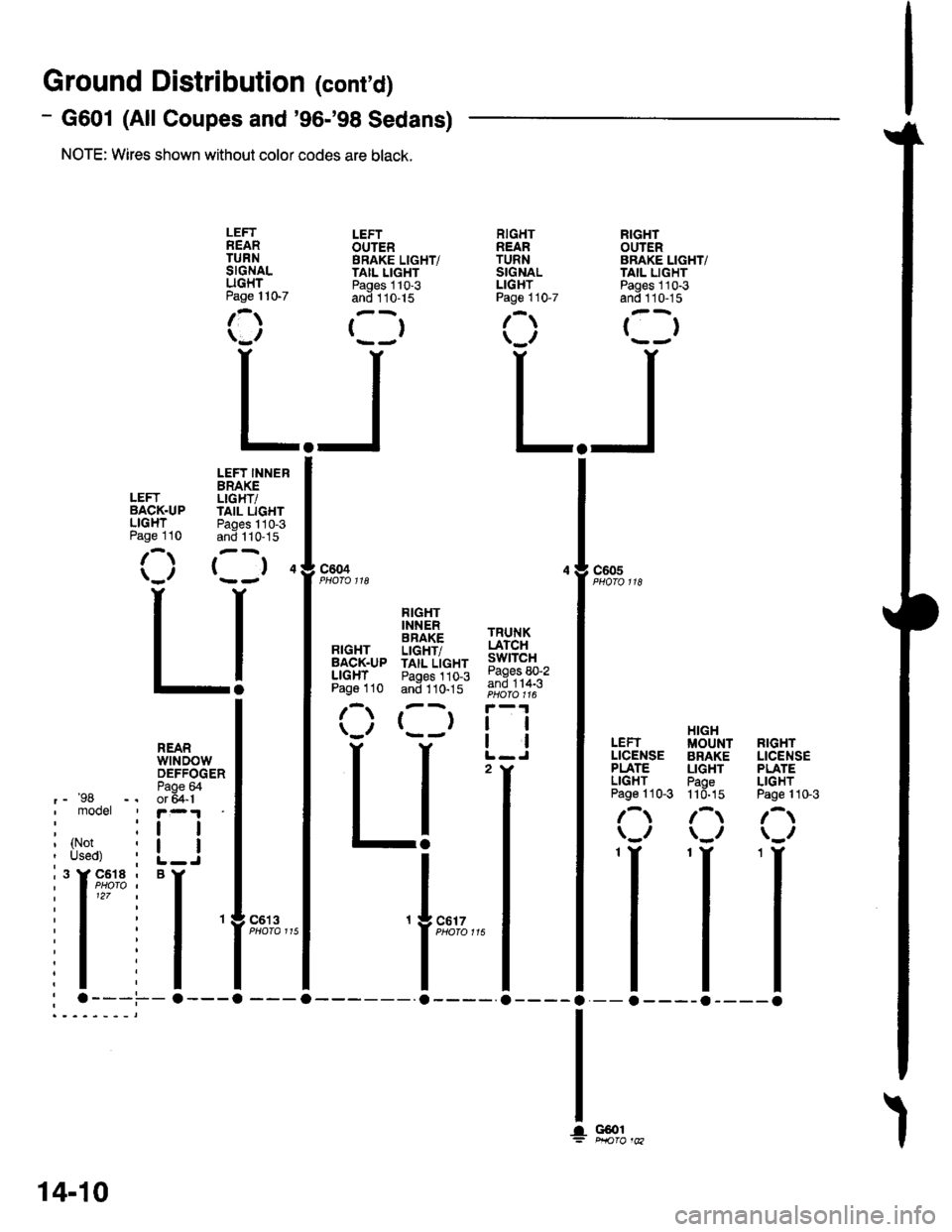
Ground Distributior (cont'd)
- G601 (All Coupes and'96-'98 Sedans)
NOTE: Wires shown without color codes are black.
LEFTOUTERBRAKE LIGHT/TAIL LIGHTPages 110-3and 110-15
()
LEFTBACK.UPLIGHTPage 110
LEFT INNERBRAKELIGHT/IAIL LIGHTPages 110-3and 1 10-15
( )4c604c605
RIGHTBACK.UPLIGHTPage 110
FIGHTINNERBRAKELIGHT/TAIL LIGHTPages 110-3and 110-15
()
TRUNKLATCHswtTcHPages 80-2and 114-3
tl
!l
2
HIGHIUOUNT RIGHTBRAKE LICENSELIGHT PLATEPaoe LIGHT11d-15 Page 110-3
/-t /-t\_/ \_/
II-a----o
LEFTLICENSEPLATELIGHTPage 110-3
\,,
REARwtNDowDEFFOGERPaoe &'-'98 -, or 5a-1I mooet ' r-.1
: :r I
I tl?l,r i L_J
i'l'* i
'l
: .---.-.---a
c6't 3
G@1
14-10
Page 1868 of 2189
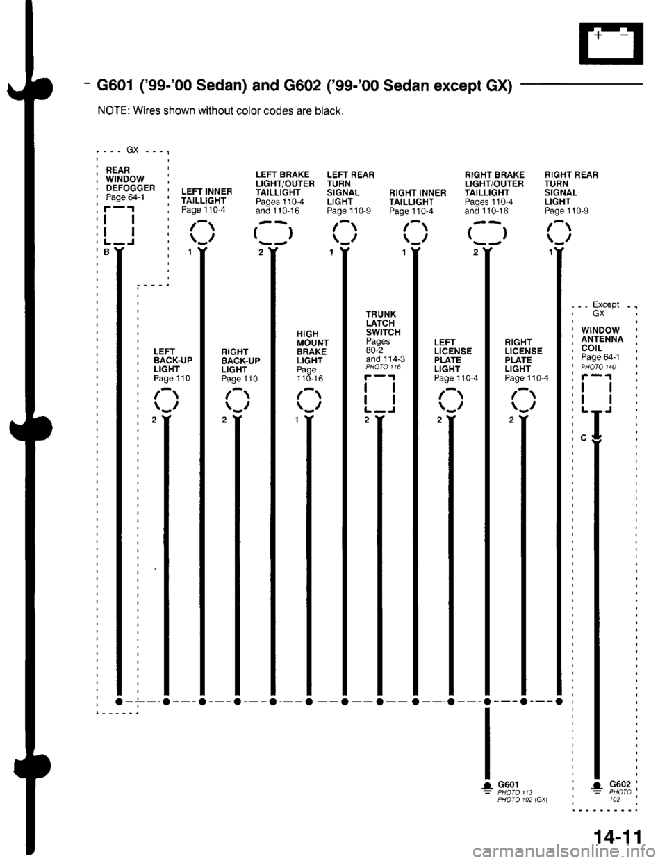
- G601 ('99-'00 Sedan) and G602 ('99-'00 Sedan except GX)
NOTE: Wires shown without color codes are black.
.--- GX ---'
: REAR I, LEFT BRAKE LEFT REAR RIGHT SRAKE RIGHT REABr/:rrT/|.rr rYEo Tr rDNI':':XX:.. ' LIGHT/OUTER TURN LIGHT/OUTER TURN
I's":" ' ; TAILLIGHT Pages 110-4 LIGHT TAtLLtcHT Pages 110-4 LIGHT
i-''! ' Page 110-4 and 1t0-16 Page 110-9 Page 110-4 and tto-to Page 110-9
I i I /- r--r /-r /- ,--r /-r
L_j i \_,, l--, \_,, \_,, t--, \_.,
BT : lY 2Y 1Y 1Y 2Y ,I
illllll,,**
i I I I UY8,f I I li ll
: I lm,r.-15fi[8"]=.. 1""", lir^l+:nv^i
$"o^',lJ I 33n'" I lffJ"* I l,8gJ". l:33iii bi['*.u, I Bigil" I r,Hll' | ::i''". I i'&+" I i'&?t" | :3:#*' i
i !filifl ig"m l il!il I it'i. l i,H':,,. I i:Hi,.. I i i&T i
ir-> | r:> | r:; IL-i I r:; I c; IiL-j i
i )v' | )v' | )v' | ;vr I )v' | )v' li:-T T _I T T T -I I _I T _T T:
: I I I I I I I I I I I l:"9
: I T I T T T T I T T I T:
; I I I I I I I I I I I I;
: I I T T I T T I I T I T:: I I I I I I I I I I I I:t
: I T T I I T T T T T I T;I
: I I t I I I I I I I I I:t
: I T I T T T T I T I T I:T :
: I I I I I I I I I I I l:t
:.1 I I I I I I I I I I l; I :
: I I I I I I I I I I I t: I :
: I I T I I T T I T T T T; T
: I I I T T T I I T T T I; I
: I I I I I I I I I I I I: I :
, I I I I I I I I I I I l; I :
; I I I I I I I I I I I I'
: I I I I I I I I I I I l. I, I I I I I I r I I I r r; I
14-11
TRUNK T I I' GX
:t:
l'r,I G601 : t G602 :: Ptl1fo 113 , : PHafa ,PHOrO 102 lGXl 142 :
Page 1869 of 2189
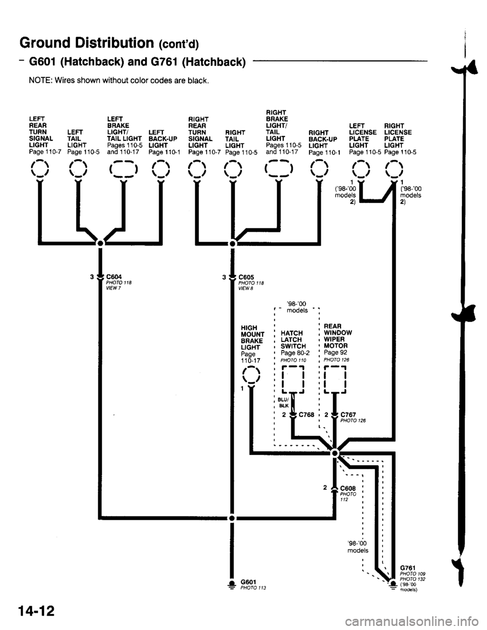
Ground Distribution (cont'd)
- G601 (Hatchback) and G761 (Hatchback)
NOTE: Wires shown without color codes are black.
LEFTREARTURNSIGNALLIGHTPage 110-7
LEFTTAILLIGHTPage 110-5
LEFTERAKELIGHT/TAIL LIGHTPages 110-5and 110-17
()
LEFTBACK.UPLIGHTPage 1 10-1
RIGHTREARTUNN FIGHTSIGNAL TAILLIGHT LIGHTPage 110-7 Page 110-5
RIGHTBRAKELIGHTiTAILLIGHTPages 110-5and 110-17
()
: HATCH; LATCH, swrTcH' Page 80-2' PHO|O 11A
:l I;l I
. BLU/I BLK
i2
'98-'�00
models ' :
:t I
i L-J
czsa izlczszPHO|O 126
LEFT RIGHTLICENSE LICENSEPLATE PLATELIGHT LIGHTPage 110-5 Page 110-5
/-.t r-t\_,, \_,,I(98-'00mooets2)
G761PHOTO 109PHO|O 132(98i00
RIGHTBACK.UPLIGHTPage 1 10- l
c605
vlEw a
HIGHMOUNTBRAKELIGHTPage110- t7
G601
: REAR; wlNDow. WIPER, MOTOR' Page 92
r-t lr-t\_, \_,,
II
ll
l-y-
14-12
'.!
Page 1983 of 2189
A/T Gear Position Indicator (conrd)
- How the Circuit Works
With the ignition switch in ON (ll) or START (lll),
voltage is applied to the A,/T gear position indicator.
The A,/T gear position switch provides a ground for
each position. As an input is grounded, its indicator
light comes on. lf you select R, for example, ground
will be provided to the input of the A,/T gear position
indicato( and the R indicator will come on.
With the headlight switch in PARK or HEAD, voltage
is applied to the RED/BLK wire terminal. This
changes the indicator panel illumination from fixed
to controlled by the dash lights dimmer input
through the RED wire.
When the powertrain (all except '96-'98 CVT) or
transmission ('96198 CVT) control module (PCM or
TCM) detects an abnormality in the automatic
transmission control system, or when you request
diagnostic trouble codes through the service check
connector, the PCM or TCM will make the D4 (D for
CVT) indicator light blink.
Refer to the Service Manual (Section 14,
Automatic Transmission) for specific tests or
troubleshooting procedures.
\ia
89-2
Page 2026 of 2189
Power Door Locks (cont'd)
- How the Circuit Works
Keyless Entry System
The keyless door locks combine the power door
locks with a remote keyJob transmitter. The keyless
receiver unit is part of the radio. The keyless
receiver unit receives direct inputs f rom the ignition
key switch, the passenger door switches, and an
indirect input trom the driver's door switch through
the integrated control unit.
Power Door Locks (With or Wlthout Keyless)
The power door lock system is made up of the
oower door lock control unit. driver's door lock
switch, and individual door lock actuators. The
power door locks are controlled by the driver's door
lock switch and the driver's door lock actuator
switch.
Transmitter (With Keyless Entry)
The transmitter sends coded radio wave signals to
the keyless receiver unit when one ot its buttons is
pressed. Each transmitter has a unique code that
must be 'laught" to the keyless receiver unit before
it can operate the door locks or any other lunction.
Up to 4 transmitters can be programmed to operate
the keyless door locks.
Door Locking (With or without Keyless Entry)
When you push the driver's door lock switch to the
lock position, ground is applied to the GBN/IVHT
wire to the oower door lock control unit. The control
unit then applies battery voltage to the WHT/RED
wire and ground to the YEURED wire. The
passenger door lock actuators then activate to lock
the corresponding door locks.
When you lock the driver's door with the key or door
lock knob, it is mechanically locked, and the driver's
door lock actuator switch applies ground to the
oower door lock control unit. The control unit then
applies battery voltage to the WHT/RED wire and
ground to the YEURED wire, activating the
passenger door lock actuators which lock the doors.
Dool Locking with Transmitter
When you press the LOCK button on the remote
transmitter, the power door lock control unit applies
battery voltage to the WHT/RED wire and ground to
the YEURED wire. The passenger door lock
actuators then activate and lock the doors. A ground
slgnal is also applied to the BLU/RED wire to lock
the driver's door. lf any door is open, you cannot lock
it using the remote transmitter.
Door Unlocking (With or Without Keyless Entry)
When you push the driver's power door lock switch
to the unlock position, ground is applied to the
GRN/ORN wire to the power door lock control unit.
The control unit then applies battery voltage to the
YEURED and BLU/RED wires and ground to the
WHT/RED wire. The door lock actuators then
activate to unlock the doors.
When you unlock the driver's door with the key or
the door lock knob, it is mechanically unlocked; the
other doors do not unlock.
Door Unlocking (With Transmltter)
When you press the UNLOCK button on lhe remote
transmitter once. the power door lock control unit
applies battery voltage to the WHT/RED wire and
ground to the BLU/RED wire to unlock the driver's
door. When you press the UNLOCK button twice,
the control unit then applies ground to the YEURED
wires to activate the passenger door locks. lf you do
not open a door within 30 seconds after unlocking
the doors with the transmitter, the doors
automatically relock.
Transmltter Programming
1 . Turn the ignition switch ON (ll).
2. Press and hold the Valet-Disarm button on the
radio (between the AM/FM button and the
CD/TAPE button) to enter the programming
mode. (Continue to hold the button during the
procedure, or programming will be cancelled.)
Check that the power door locks cycle to confirm
that you're in the programming mode.
3. Press the "LOCK' or "UNLOCK' button on the
transmitter. Check that the power door locks
cycle to confirm that the code was accepted.
4. Press the "LOCK" or "UNLOCK" button on each
of the remaining transmitters. (You can program
up to four transmitters per vehicle.)
5. After all the transmitters have been
programmed, release lhe Valet-Disarm button to
exit the programming mode.
Beep On/Oft Feature
'I . Press and hold the LOCK and OPTION buttons
on the transmitter.
2. Watch the transmitter's LED:
One flash: Beeo activated.
Two tlashes: Beeo deactivated.
130-4
Page 2036 of 2189
Power Door Locks (conrd)
- How the Circuit Works
Keyless Entry System
The keyless door locks combine the power door
locks with a remote key-fob transmitter. The keyless
door lock control unit receives direct inputs from the
ignition key switch, the passenger door switches,
and an indirect inDut from the driver's door switch
through the integrated control unit.
Power Door Locks
The power door lock system rs made up ot the
keyless door lock control unit, driver's door lock
switch, and individual door lock actuators. The
power door locks are controlled by the driver's door
lock switch and the driver's door lock actuator
switch.
Transmittel
The transmitter sends coded radio wave signals to
the keyless door lock conlrol unit when one of its
buttons is pressed. Each transmitter has a unique
code that must be 'laught" to the conlrol unit before
it can operate the door locks or any other function.
Up to 4 transmitters can be programmed to operate
the keyless door locks.
Door Locking
When you push the driveas door lock switch to the
lock position, ground is applied to the GRNMHT
wire to the keyless door lock control unit. The
control unit then applies battery voltage to the
WHT/RED wire and ground to the YEURED wire.
The passenger door lock actuators then activate to
lock the corresponding door locks.
When you lock the dnver's door with the key or door
lock knob, it is mechanically locked, and the driver's
door lock actuator switch applies ground to the
oower door lock control unit. The control unit then
applies battery voltage to the WHT/RED wire and
ground to the YEURED wire, activating the
passenger door lock actuators which lock the doors.
Door Locking with Transmitter
When you press the LOCK button on the remote
transmitter, the keyless door lock control unil applies
battery voltage to the WHT/RED wire and ground to
the YEURED wire. The passenger door lock
actuators then activate and lock the doors. A ground
signal is also applied to the BLU/RED wire to lock
the driver's door. lf any door is open, you cannot lock
it using the remote transmitter.
Door Unlocking
When you push the driver's power door lock switch
to the unlock position, ground is applied to the
GRN/ORN wire to the keyless door lock control unil.
The control unit then applies battery voltage to the
YEUREO and BLU/RED wires and oround to the
WHT/RED wire. The door lock actuators then
activate to unlock the doors.
When you unlock the driver's door with the key or
the door lock knob, it is mechanically unlocked; the
other doors do not unlock.
Door Unlocking with Transmitter
When you press the UNLOCK button on the remote
transmitter once, the keyless door lock control unit
applies battery voltage to the WHT/RED wire and
ground to the BLU/RED wire to unlock the driver's
door. When you press the UNLOCK button twice,
the control unit then applies ground to the YEURED
wires lo activate the passenger door locks. lf you do
not open a door within 30 seconds after unlocking
the doors with the transmitter, the doors
automatically relock.
Transmitter Programming
. Entering the programming mode cancels all
learned transmitter codes, so none of the
previously programmed transmitters will work.
You must reprogram all the transmitters once
you're in the programming mode.
. To keep the system from exiting the
programming mode, complete each step within 5
seconds of the previous step, and program the
transmitters within 10 seconds of each other.'1 . Turn the ignition switch ON (ll).
2. Press the "LOCK" or "UNLOCK" button on one
of the transmitters. (A non-programmed
transmitter can be used for this step.)
3. Turn the ignition switch OFF (0).
4. Repeat steps 1, 2, and 3 two more times with
the transmitter used in step 2.
5. Turn the ignition switch ON (ll).
6. Press the "LOCK" or "UNLOCK" button on the
same transmitter. Check that the power door
locks cycle to confirm that you're in the
programmrng mooe.
7. Press the "LOCK" or "UNLOCK" button on each
lransmitter. (You can program up to four
lransmitters per vehicle.) Check that the power
door locks cycle after you push each transmitter
button, contirming that the system has accepted
the transmitter's code.
Beep On/Off Feature
1 . Press and hold the LOCK and OPTION buttons
on the transmitter.
2. Watch the transmitter's LED:
One flash: BeeD activated.
Two flashes: Beep deactivated.
130-14
Page 2055 of 2189
How the Circuit Works
Arming the Security System
The security system can be armed:
r By pressing the remote control LOCK button
(if equipped)
. 20 seconds atter closing all doors (C)UDX only)
Arming with the Transmitter
The security system can be armed by removing the
ignition key from the ignition switch, closing all
doors and the trunk, and pressing the LOCK button
on the transmitter. When you arm the system in this
way, the remote control LED comes on, the status
LED flashes once per second, the parking lights
flash once. the doors lock. and the horn sounds
once if the beeo sound mode is on.
Passive Arming (CX and Dx only)
When you turn the ignition to OFF, remove the
ignition key from the ignition switch, and close all
the doors and the trunk; the system will
automatically arm itself 20 seconds after the trunk
or last door is closed. When you arm the system
this way, the status LED tlashes 4 times per second
during the exit delay time, and once per second
after the system is armed; the parking lights will
flash once to confirm that the system is armed.
Triggering the Alarm
Atter you've armed the system, it will trigger the
alarm if any door or the trunldhatch is opened. lf the
battery is disconnected when the system is armed or
in the alarm mode, reconnecting it will immediately
trigger the alarm. When the alarm is triggered, the
following will occur for 30 seconds:
. the horn sounds
o the parking lights flash once per second
. the status LED flashes hvice oer second
. the starter is disabled
After 30 seconds, the alarm will stop and the
system will rearm. Pressing the transmitter
UNLOCK button will disarm the svstem.
tlr
133-13
Disarming the System without the Remote
Transmitter (HX, LX, and EX)
You can disarm the system by turning the ignition
switch to ON (ll) and pressing the disarm/valet
switch on the right side ol the stereo tuner face. The
disarm switch will also disarm the svstem after the
system has been triggered.
Disarming the System with the Remote
Transmitter (Hx, Lx, Ex, DX-V, and Si)
Pressing the transmitter UNLOCK button will disarm
the system. The parking lights llash t\ivice if the
alarm has not been tnggered. The parking lights
flash three times if the alarm has been triggered.
The driver's door will unlock. lf you press the unlock
button twice, it will unlock all doors. lf a door is not
opened within 30 seconds, the system will lock all
doors and rearm.
Disarming the System (CX and DX only)
lf the system arms itself, there is a 20 second delay
after you open a door before the alarm will trigger.
To disarm the system in this mode, simply turn the
ignition switch to the ON position
ldentitying Tripped Sensors
The system identifies which sensor trips the alarm
by flashing the status LED. To display the trip
sensor flash code, press the disarm/valet switch 3
times within 5 seconds after the system has been
disarmed. The status sensor will blink according to
the followino codes:
SensorsNumber of Flashes
Door
TrunldHatch
System Switches
1 blink, pause, repeat
2 blinks, pause, repeat
3 blinks, pause, repeat
For further operating instructions, see the security
syslem owner's manual.
(cont'd)