Code 38 HONDA CIVIC 1997 6.G Workshop Manual
[x] Cancel search | Manufacturer: HONDA, Model Year: 1997, Model line: CIVIC, Model: HONDA CIVIC 1997 6.GPages: 2189, PDF Size: 69.39 MB
Page 1755 of 2189
l
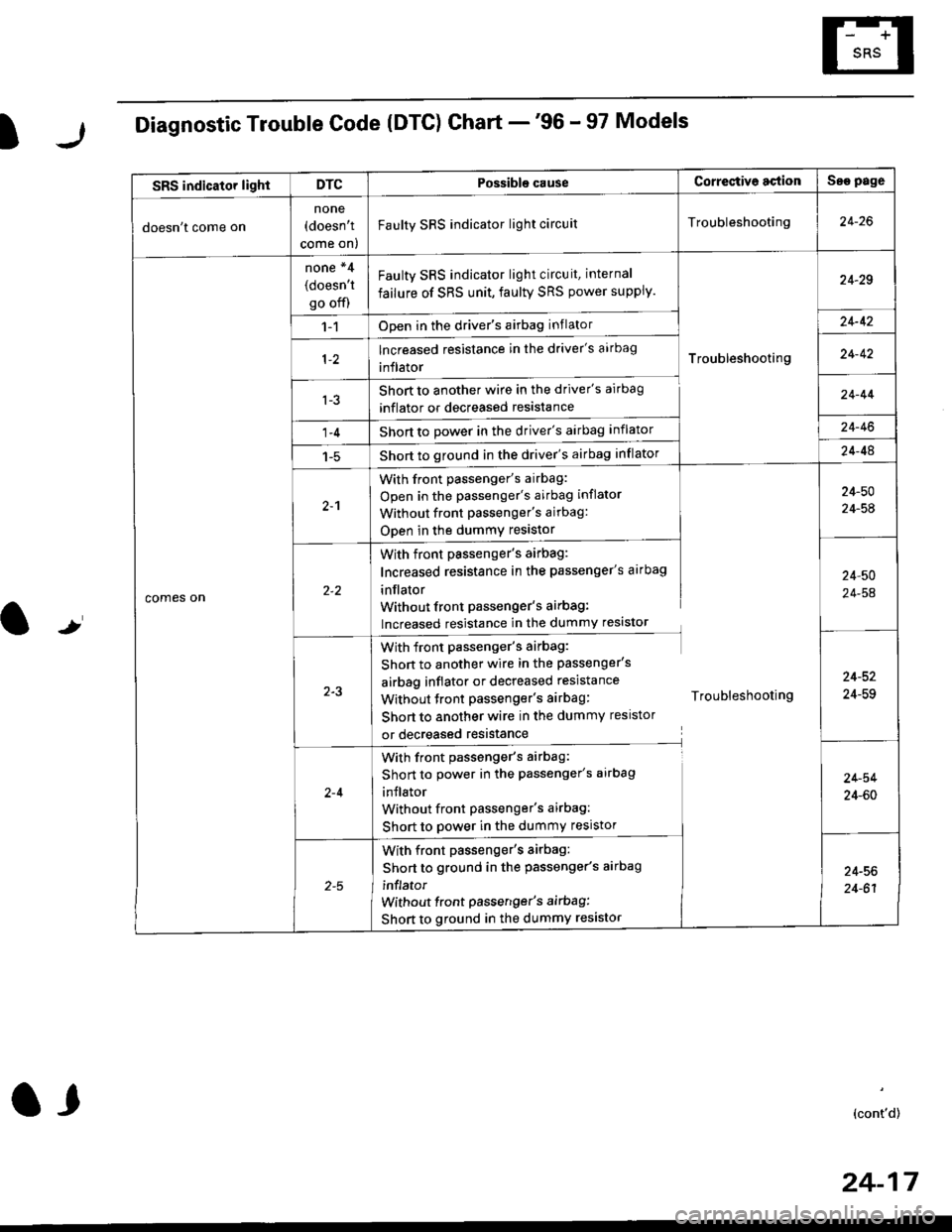
Diagnostic Trouble Code (DTG) Chart -'96 - 97 Models
t
SRS indicator lightDTCPossible causeCorrectiv6 actionSae page
doesn't come on
none(doesn't
come on)
Faulty SRS indicator light circuitTroubleshooting24-26
comes on
none *4
(doesn't
go off)
Faulty SRS indicator light circuit, internal
failure of SRS unit, faulty SRS power supply.
Troubleshooting
24-29
1-1Open in the driver's airbag inflator24-42
lncreased resistance in the driver's aarbag
inflator24-42
l-3Short to another wire in the driver's airbag
inflator or decreased resistance
Short to Dower in the driver's airbag inflator
Short to ground in the driver's airbag inflator
24-44
1-424-46
1-524-48
2-1
With front passenger's airbag:
Open in the passenger's airbag inflator
Without front Passenger's airbag:
ODen in the dummy resistor
24-50
24-54
With front passenger's airbag:
Increased resistance in the passenger's airbag
inflator
Without front Passenger's airbag:
lncreased resistance in the dummy resistor
24,50
24-54
2-3
With front passenger's airbag:
Shon to another wire in the passenger's
airbag inflator or decreased resistance
Without tront passenger's airbag: Troubleshooting
Short to another wire in the dummy resistor
or decreased resistance
24-52
24-59
2-4
With front passenger's airbag:
Short to power in the passenger's airbag
inJlator
Without front Passenger's airbag:
Short to power in the dummy resistor
24-54
24-60
With front passenger's airbag:
Short to ground in the passenger's aarbag
inflator
without front passenger's airbag:
Short to ground in the dummy resistor
24-56
24-61
(cont'd)
24-17
a,
Page 1756 of 2189
Troubleshooting
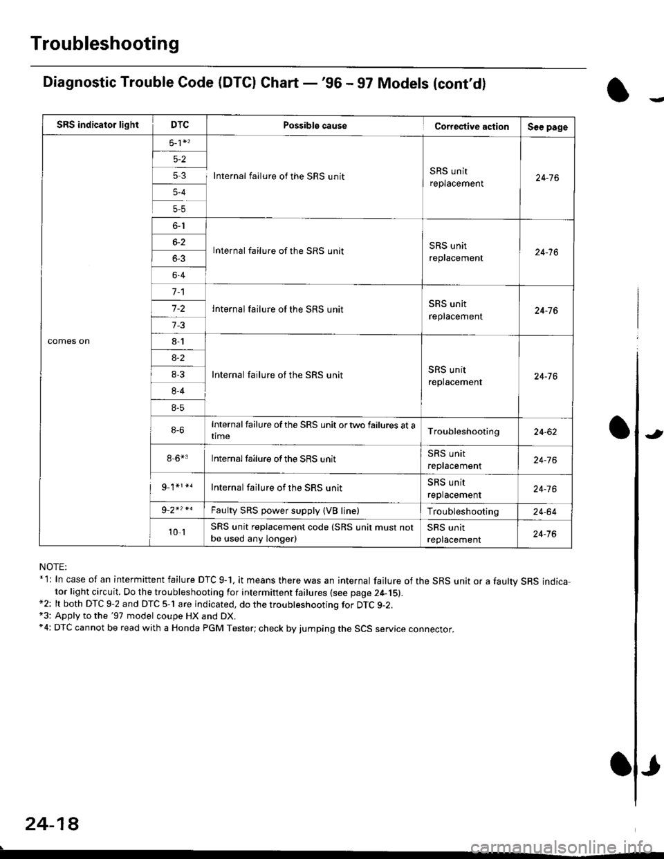
Diagnostic Trouble Code (DTCI Ghart -'96 - 97 Models (cont'd)
NOTE:* l: In case of an intermittent failure DTC g-1, it means there was an internal failure of the SRS unit or a faultv SRS indicator light circuit. Do the troubleshooting for intermittent failures (see page 24-15).*2: lt both DTC 9-2 and DTC 5-1 are indicated, do the troubleshooting for DTC g-2.*3: Apply to the '97 model coupe HX and DX.*4: DTC cannot be read with a Honda PGM Tester; check by jumping the SCS service connector.
24-18
.
Possiblg cause Cortestive action
5 3 I Internal failure of the SRS unitSRS unit
replacement
lnternal failure of the SRS unitSRS unit
replacement
Internal failure of the SRS unit
Internal failure of the SRS unitSRS unit
replacement
Internalfailure of the SRS unit ortwo failures at atime
8-6*3 Internalfailure ofthe SRS unit
Internal failure of the SRS unit
Faulty SRS power supply (VB line)
SRS unit replacement code (SRS unit must not
be used any longe.)
J
Page 1757 of 2189
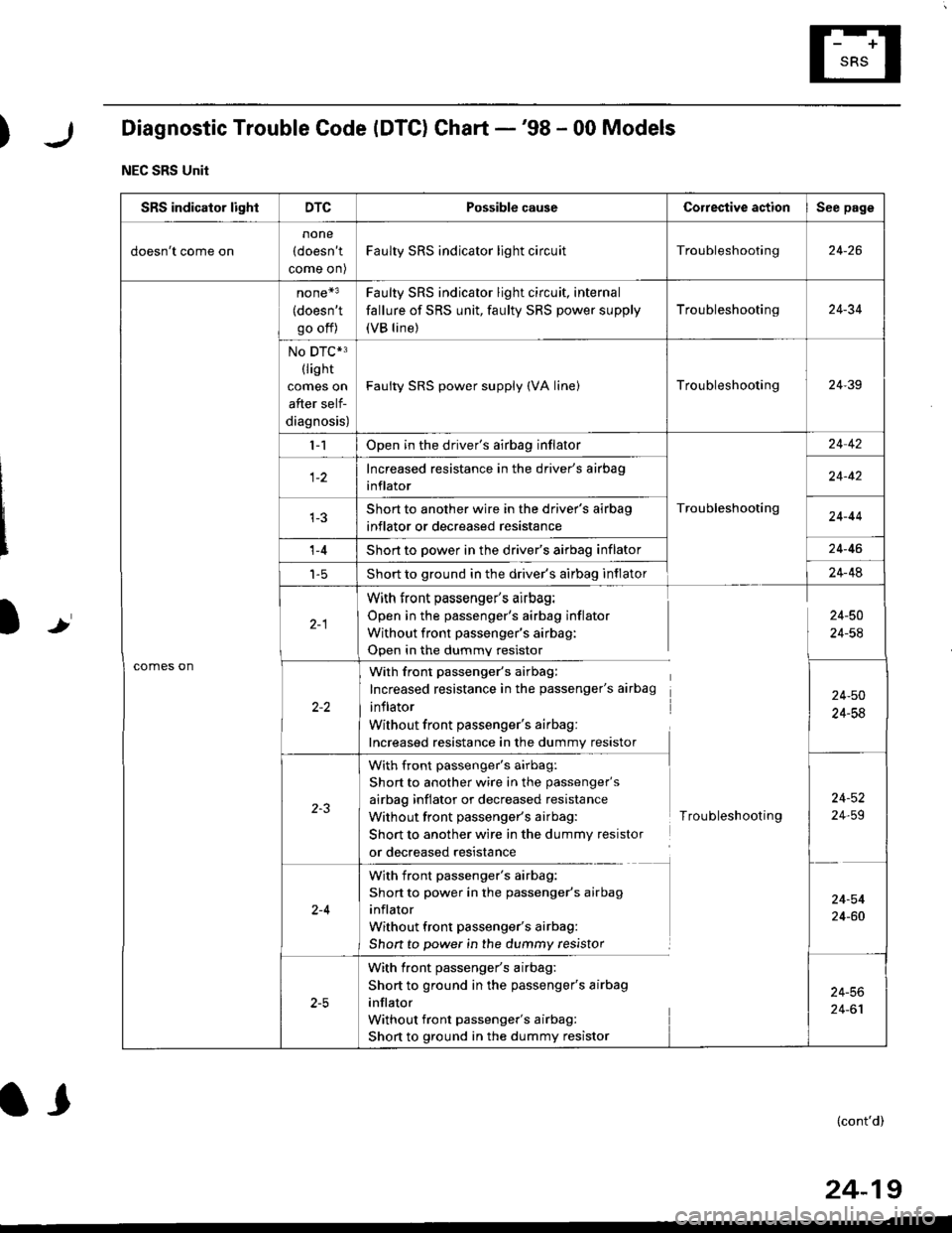
)Diagnostic Trouble Code (DTC) Chart -'98 - 00 Models
NEC SRS Unit
Ir
SRS indicator lightDTCPossible causeCorrestive actionSee page
doesn't come on
none
(doesn't
come on)
Faulty SRS indicator light circuitTroubleshooting24-26
comes on
none*3
(doesn't
go off)
Faulty SRS indicator light circuit, internal
fallure of SRS unit, faulty SRS power supply
(VB line)
Troubleshooting24-34
No DTC*3(lis ht
comes on
after self-
diagnosis)
Faulty SRS power supply (VA linelTroubleshooting24-39
l-1Open in the driver's airbag inflator
Troubleshooting
24 42
Increased resistance in the driver's airbag
inflator24-42
Short to another wire in the driver's airbag
inflator or decreased resistance24-44
't -4Short to power in the driver's airbag inflator24-46
t-5Short to ground in the driver's airbag inflator24-48
With front passenger's airbag:
Open in the passenger's airbag inflator
Without front passenger's airbag:
Open in the dummv resistor
24-50
24-54
With front passenger's airbag:
Increased resistance in the passenger's airbag
inflator
Without front passenger's airbag:
Increased resistance in the dummy resistor
24-50
24-58
with front passenger's airbag:
Short to another wire in the passenger's
airbag inflator or decreased resistance
Without front passenger's airbag:
Short to another wire in the dummy resistor
or decreased resistance
Troubleshooting
24-52
24,59
2-4
With front passenger's airbag:
Short to power in the passenger's airbag
inflator
Without front passenger's airbag:
Shon to power in the dummy resistor
24-54
24-60
With front passenger's airbag:
Short to ground in the passenger's airbag
inflator
Without front passenger's airbag:
Short to ground in the dummy resistor
24-56
24-61
(cont'd)
24-19
l,
Page 1758 of 2189
Troubleshooting
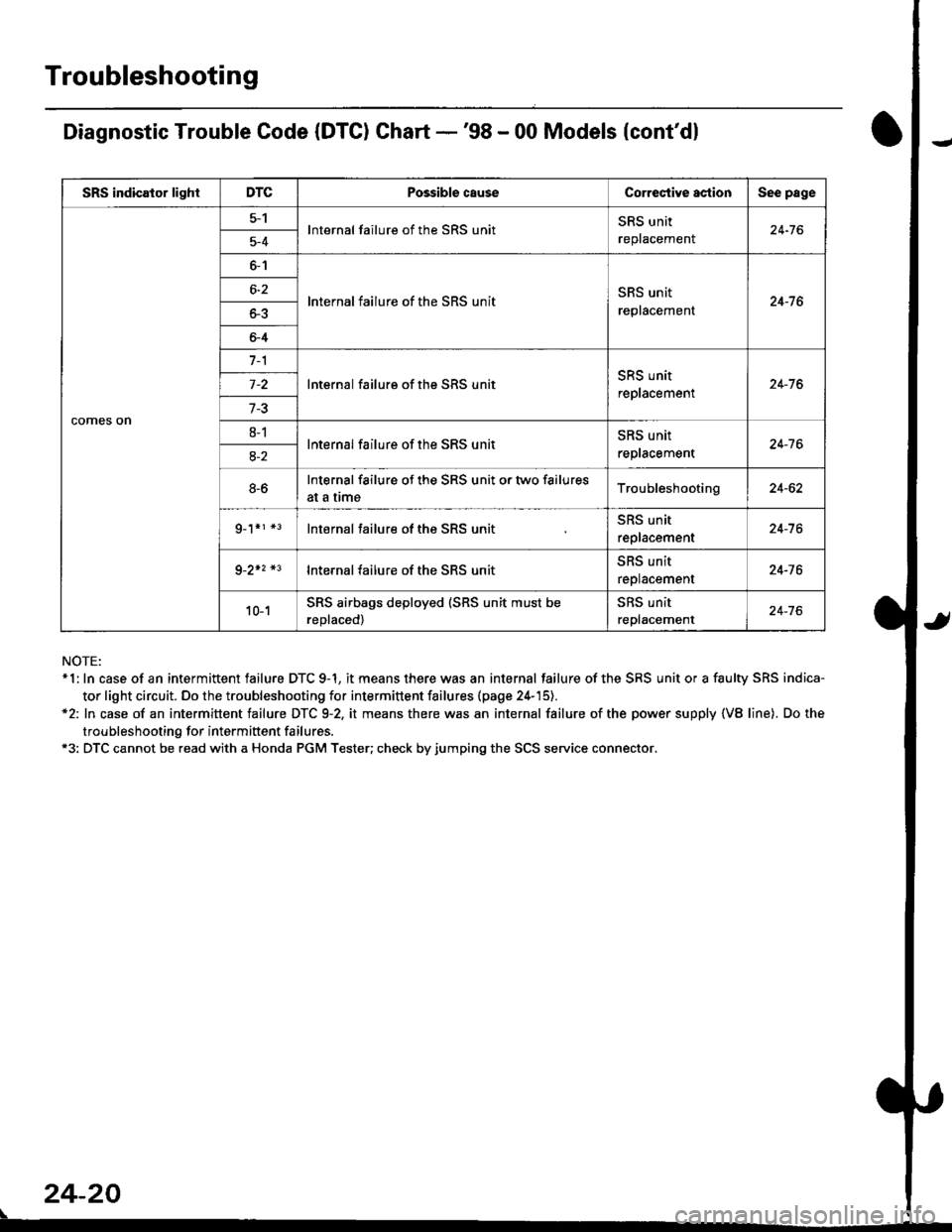
Diagnostic Trouble Code (DTC) Chart -'98 - 00 Models {cont'dl
NOTE:* 1: In case of an intermittent failure DTC 9-1, it means there was an internal failure of the SRS unit or a faulty SRS indica-
tor light circuit. Do the troubleshooting for intermittent failures (page 24-'15).*2: In case of an intermittent failure DTC 9-2, it means there was an internal failure of the power supply {VB line). Do the
troubleshooting for intermiftent failures.*3: DTC cannot be read with a Honda PGM Tester; check by jumping the SCS service connector.
24-20
\
SRS indicator lightDTCPossible causeCorrectiYe actionSee page
comes on
5-1lnternal failure of the SRS unitSRS unit
replacemenl24-765-4
6-1
lnternal failure of the SRS unitSRS unit
replacement24-7 66-2
o-5
6-4
7-1
lnternal failure of the SRS unitSRS unit
replacement24-76
7-3
8-1lnternal failure of the SRS unitSRS unit
reptacement24-7 68-2
8-6Internal failure of the SRS unit or two failures
at a trmeTroubleshooting24-62
g_1*r *3lnternal failure of the SRS unitSRS unit
replacement24-7 6
9-2+2 *3lnternal failure of the SRS unit5l|5 Untr
replacement24-76
10-1SRS airbags deployed (SRS unit must be
reDlaced)
SRS unit
replacement24-76
Page 1760 of 2189
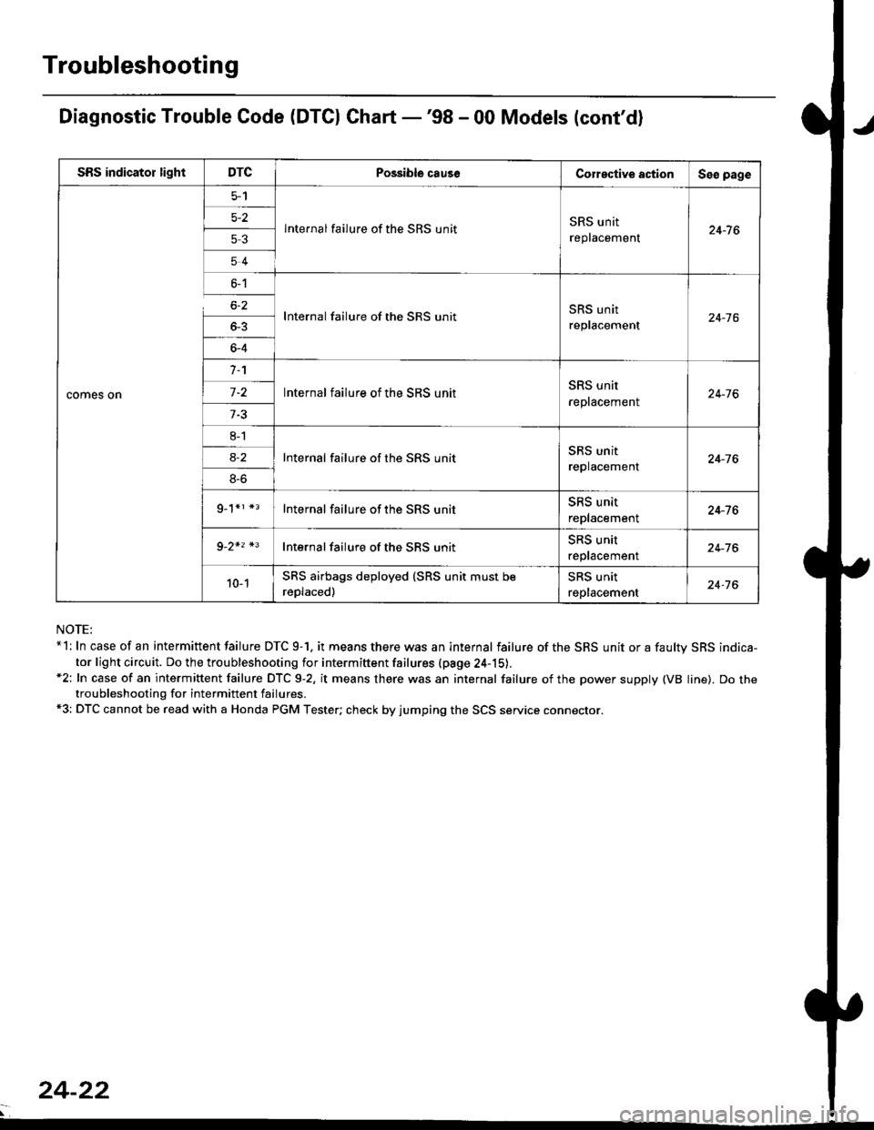
Troubleshooting
Diagnostic Trouble Code (DTCI Ghart -'98 - 00 Models (cont'd)
NOTE:*l: In case of an intermittent failure DTC 9-1. it means there was an internal failure of the SRS unit or a faultv SRS indica-
tor light circuit. Do the troubleshooting for intermiftent failures (pa9e 24-15).*2: In case of an intermittent failure DTC 9-2, it means there was an internal failure of the power supply (VB line). Do thetroubleshooting for intermittent failures.*3: DTC cannot be read with a Honda PGM Tester; check by jumping the SCS service connector.
SRS indicator lightDTCPossible causeCorective actionSeo page
comes on
5-2
53
54
lnternal failure of the SRS unitSRS unit
replacement24-7 6
6-1
6-2
_
64
Internal failure of the SRS unitSRS unit
replacement24-16
n
-
8l
8S
9_1*r *3
Internal failure of the SRS unitSRS unit
reptacement24-76
Internal failure of the SRS unitSRS unit
replacement24-76
Internal failure of the SRS unitSRS unit
replacement24-76
Internal failure of the SBS unitSRS unit
reptacemenr24-76
10-1SRS airbags deployed (SRS unit must be
reDlaced)
SRS unit
replacement24-76
24-22
Page 1762 of 2189
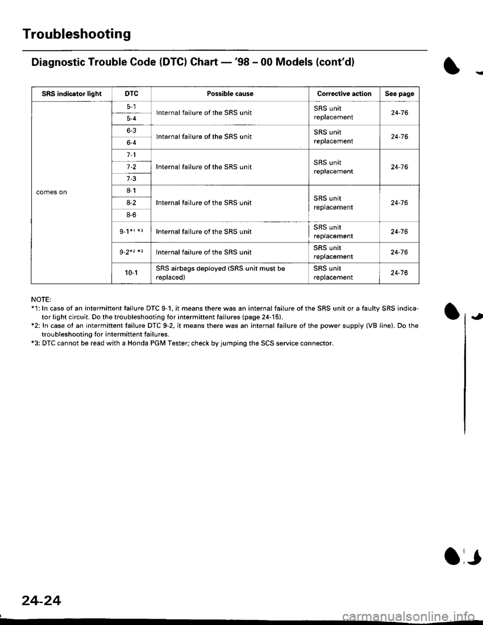
Troubleshooting
Diagnostic Trouble Code (DTG) Chart -'98 - 00 Models (cont'dl
NOTE:*'l: In case of an intermittent failure DTC 9-1. it means there was an internal failure of the SRS unit or a faulty SRS indica-
tor light circuit. Do the troubleshooting for intermiftent failu.es (page 24-15).*2: In case ot an intermittent failure DTC 9-2. it means there was an internal failure of the power supply (VB line). Do the
troubleshooting for intermift ent failures.*3: DTC cannot be read with a Honda PGM Tester; check by jumping the SCS service connector.
24-24
a,
SRS indicator lightDTCPossible causeCorective actionSee page
comes on
lnternal failure of the SRS unitSRS unit
repracemenl24-765-4
6-3lnternal failure of the SRS unitSRS unit
reptacemenr24-766-4
Internal failure of the SRS unitSRS unit
replacement24-7 6
8-1
lnternal failure ot the SRS unitSRS unit
replacement24-7 68-2
8-6
g_1*r *rInternal failure of the SRS unitSRS unit
replacement24-16
lnternal failure of the SRS unitSRS unit
repracemenl24-76
10-1SRS airbags deployed (SRS unit must be
.eplaced)
SRS unit
reptacemenl24-76
Page 1857 of 2189
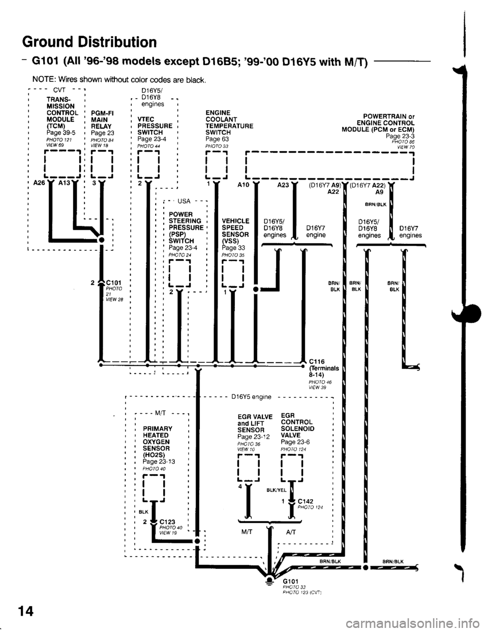
Ground Distribution
- Gl01 (All '96-'98 models except D1685; '99100 D16y5 with M/T)
NOTE: Wires shown without color codes
:--- CVr --' D16y5/
i rnlts_ ' ._ 016y8,MISSION',englnes
: CONTROL ' PGM.FI :: MODULE i UAIH ; VTEC, TTCM) ; RELAY . PRESSURE' Paae 39-5 ' Paoe 23 ' SWITCHI pHdro et ' n 6roao ' Page 23-4I vtEw 69 | vtEw 1a ' pHoro 44' r---.t ' r-1 I i-r
POWERTRAIN orENGINE CONTROLMODULE (PCM or ECM)Page 23-3PHATO 86vlEw 7a; r---1 ;r-1 , r, I t,t | ,l
: I t:t | :l, L---J, L-J ' L-, A26Y A13Y , 3,2
i T T: I I
I I, I t,,-I T T: T i
: I t:--I-. :
i I \li:; -4, ;!-------------l-i '
'lF;% :21 ,vlEw 28 ;
_ - t\4/T -
PRIMARYHEATEDOXYGENSENSOR(H02S)Page 23-13
ll
tl
"i[",..
14
o---1\
I
Page 1859 of 2189
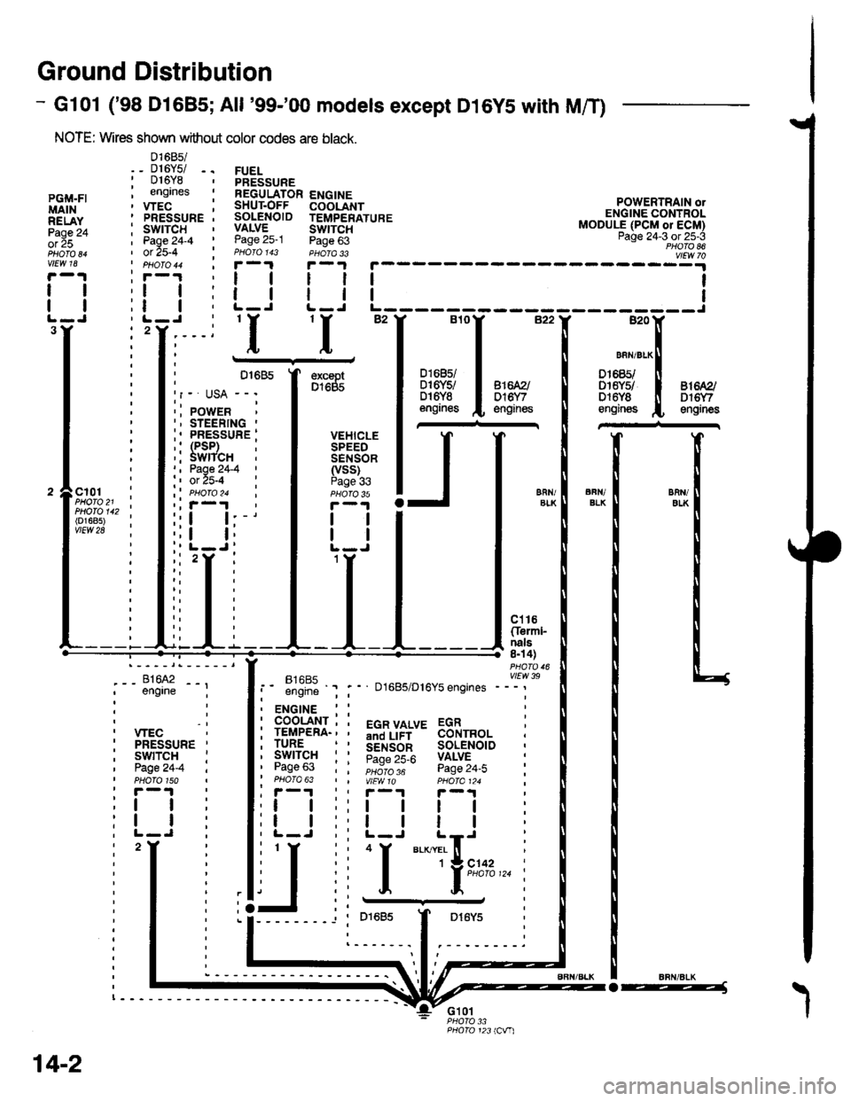
Ground Distribution
- Gl01 ('98 Dl685;All '99-'00 models except D16YS with M/T)
NOTE: Wires shown without color codes are black.
01685/_ D16Y5/ -.016Y8engrnes
.__-;,#'-_,--', engrne ;
, wEc: PRESSURE '
, swtTcH :I Page24-4 iI PHOTO 150: r -'l
:t | :
:l | :,L-J.
FUELPRESSUREREGULATOR ENGINESHUT.OFF COOLANTSOLENOID TEMPERATUREVALVE SWTTCHPage 25-1 Page 63PHOIO 143 PHOTA 33r-1F-.|
llll
lltlL-J L-J
POWERTRAIN olENGINE CONTROLMODULE (PCM or ECM)Page 24-3 ot 25-3PHOTO 86
----:y4
tl
tl
PGi,|.FIMAINRELAYPage 24ol 25
vlEw 18
tl
tl
3Y'I'I
excaptD1685
VEHICLESPEEDSENSOR(vss)Page 336FN/ELKERll/EIKcl01PHOTO 21PHOTO 142(o1685)vtEw 28
ct16Cferml-nals8n 4)
FltaFt( vttw 39t- .''iiti ' " D1685/D16Y5 engrnes ---'
t2
. ENGINE : :
i 933'?il-; i 5"T,Yf,*' 33i,"o, i
i lgfft" i I S.ir1".l^ soL€NorD :' Pase 63 : : ;;;;; - pase 24.i :' PHOTO 63 | | VtEWlO pHOIa124 ;, r-1 | , F-.t r-.r
:l | ;:l | ! | :;t | :,t | | | ;
j,f
ii T.__.,|,,,,,.
j
--
----- --l i otoas I Dr6y5 :
:------.1.--------.
14-2
o-----J
Page 1861 of 2189
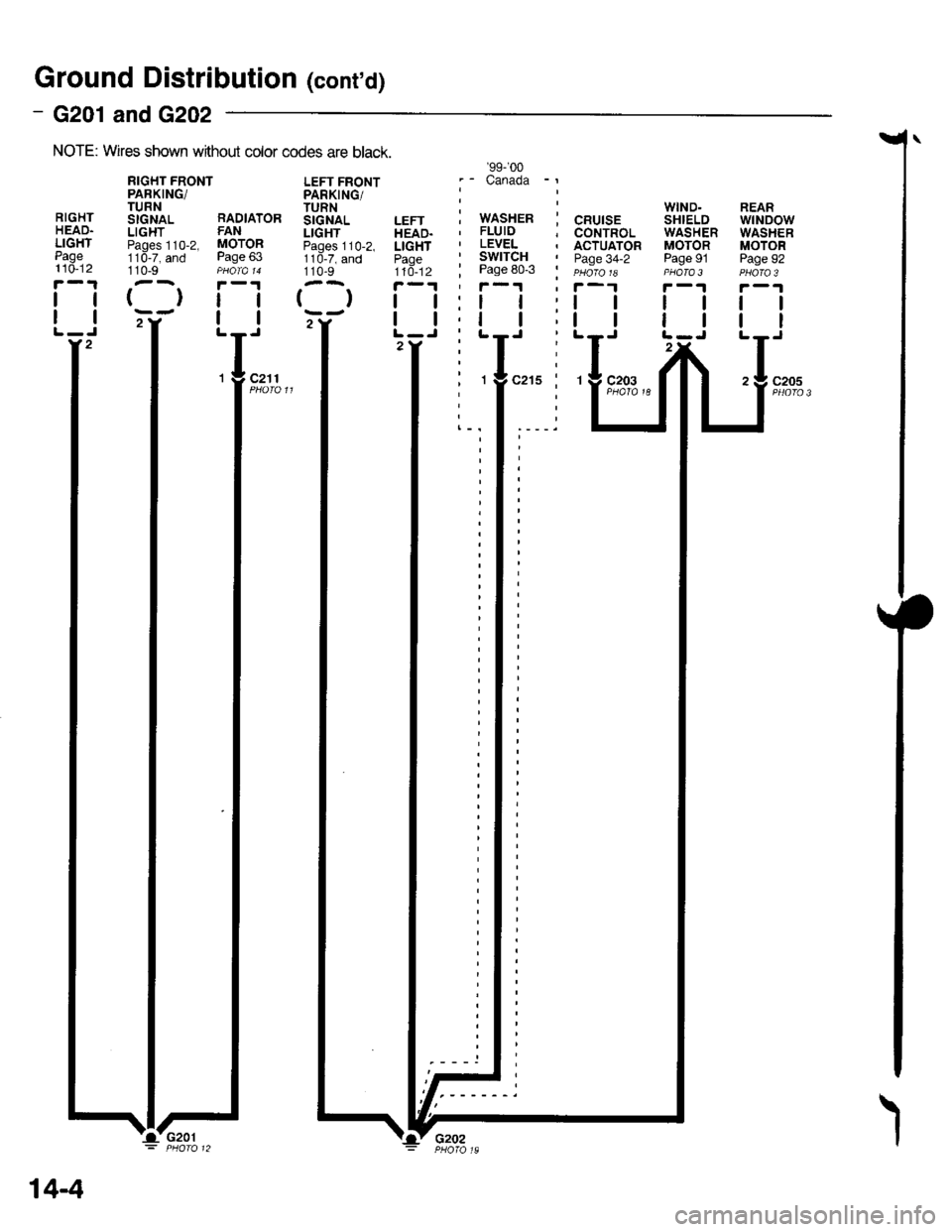
Ground Distributiofl (cont'd)
- G201 andG202
NOTE: Wires shown wrthout color codes are black.
RIGHTHEAD.LIGHTPage110-12
tl
tl
110-9
{}tl
tl
LEFT FRONTPARKING/TURNSIGNALLIGHTPages 110-2,1 10-7, and110-9
()
WIND.SHIELDWASHERMOTORPage 91PHOTA 3
ll
tl
REARwtNDowWASHERMOTORPage 92
tl
tt
c205
RIGHT FRONTPARKING/TURNStcNAL RADIATORLIGHT FANPaoes 110-2, MOTOR11d-7, and Page 63
'99-'�00
.- Canada -l
i wnsxen i cnurse, FLUID ; CONTROL' LEVEL . ACTUATOR' SWITCH I paoe 34-2; Page 80-3 i eu6ro re'f-1 ' f-1
2Y2
c211
14-4
I'G201'Lv G2o2
Page 1862 of 2189
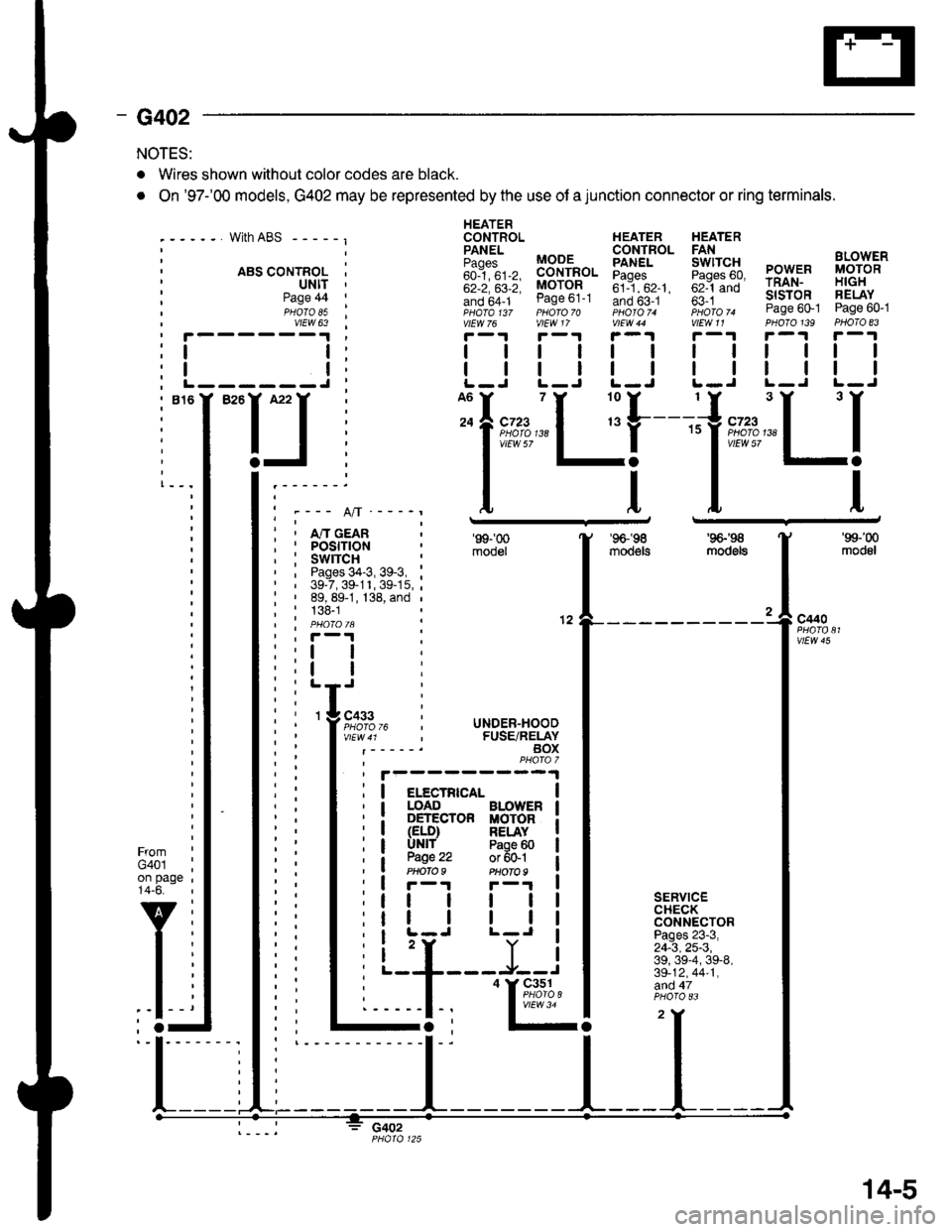
- G402
NOTES:
. Wires shown without color codes are black.
. On '97-'00 models, G402 may be represented by the use of a junction connector or ring terminals.
with ABS - - - - - I
. ABS CONTROL I' ultt '
HEATERCONTROL HEATER HEATER
iili, BB-'fi",. Eiff* 5fi::g PowER i,8;g'"'
;;; ;;; MoroR ;il--"'. ;;1-;; rRAN- H|GH
!if,6f1- ease ot-t Ino b5-.t ' fi i *- slsroR FELAY- ,pHaTa t3z pHoro 70 photoT. iioro ^ Page 60-1 Page 60-1vtEw 76 vlEW 17 V|EW 44 V|EW11 PHOTO139 PHOTO 83
r-1r-.!r-1r-1r-.|r-1
| | | | | | rl I lll
| | | | | | I ll ll IL-J L-J L-J L.J L-J L-J
Page 44PHOTO 85vtEW 63
I
I------J
I""IJ
Ifnn*"1 r'[
1"""LI'--- A/l ---_r
i , m cean; I POStflON, : swrrcH :' , Pages 34-3, 39-3, :' | 39-7,39-11,39-15,;: ' 89, 89-1, 138, and ,
; : 138-1| | PHO|OIA :' , F-'t .
'99-'00
mooel
'96-'�98
moo€ts
'9G'S
mod6ls
'99-'00
modol
a
12c440
vtEw 45
FromG401on page14-6.
v
l-
SERVICECHECKCONNECTORPages 23-3,24-3,25-3,39, 39-4, 39-8,39-12,44-1,afid 47
c402
I
I
3 cass
l;l:,12,
li
rc i UNDER-HOOD, FUSE/RELAYBOXPHAfa 7
I elecrRrca- |I LOAD BLOWER I: DETECTOR MOTOR iI (ELD) RELAY II UNlf Paoe 60 |
a W.': :;ffil iI r-r F-'r I
tt | | | |
tr | | | |I L-J L-J I
i 'r Y iL--+---J--J
I
'I&%,14.,I
14-5