d16 HONDA CIVIC 1997 6.G Workshop Manual
[x] Cancel search | Manufacturer: HONDA, Model Year: 1997, Model line: CIVIC, Model: HONDA CIVIC 1997 6.GPages: 2189, PDF Size: 69.39 MB
Page 544 of 2189
\J
Fuel Tank Pro3sure sensor 196 D16Y8 engine (coupe).'97 D15Y7 engine {coupe: KL model, sedan: KL (LX) modeu,'97
D16Y8 engine (coupe: all models, sedan: KL model, '98-all models) '99 - 00 D16Y5 engine with M/Tl:
\
PTANK
{LT GRNI
vcc2(YEL/BLU}
Wire side oI female terminals
FUEL TANKPRESSURE SENSOR3P CONNECTOR (C7921
sG2IGRN/8LK)
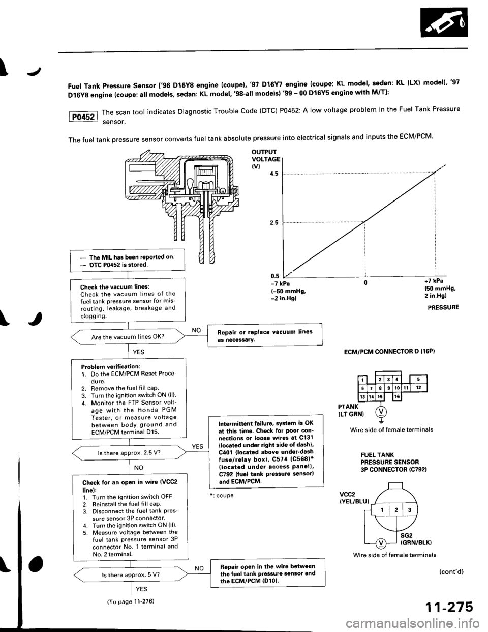
Foc2l::il":"toolindicatesDiagnosticTroublecode(DTc)P0452:A|owvo|tageprob|emintheFue|TankPressure
The fuel tank pressure sensor converts fuel tank absolute pressure into electrical signals and inputs the EcM/PCM.
OUTPUTVOLTAGEtvt4.5
-? kPa(-50 mmHg,-2 in.Hg)
ECM/PCM CONNECTOR O I16P)
Wire side of female terminals
+7 kPs150 mmHg,2 in.Hg)
PRESSURE
(cont'd)
11-275
- The MIL has been reported on- DTC P0452 is stored.
Check the vacuum lines:
Check the vacuum lines of the
fuel tank pressure sensor for mis-
routing, leakage, breakage and
cloggrng.
Are the vacuum lines OK?
Problem v€ritication:1. Do the ECM/PCM Reset Proce
dure.2. Remove the luel fill caP.
3. Turn the ignition switch ON lll)4. Monitor the FTP Sensor volt_
age with the Honda PGM
Tester, or measure voltage
between bodY ground and
ECM/PCM terminal Dl5.lntermittent tailuro, sYstem i5 OK
dt this timo. Chock for Poot con-
neciion3 or loose wir* at C131
llocatod under right side ot dashl,
C4O1 (located .bove under'da3htuso/ielay box), C574 1C568)*
{located under acc€ss Panell.C792 lfuel tank pressule sen3or)
and EcM/PCM.
ls there approx. 2.5 V?
Check tol an op€n in wite (VCC2
line):1. Turn the ignition switch OFF
2. Reinstallthe fuel fill caP.3. Disconnect the fuel tank Pres'sure sensor 3P connector-4. Turn the ignition switch ON (ll)
5, Measure voltage between the
fuel tank pressure sensor 3P
connector No. l terminal and
No. 2 terminal.
Repair open in the wite betweenthe fuel tank Pr€s3ure a€n3or andth6 EcM/PcM (D1ol.ls there approx. 5 V?
(To page 11'276)
Page 548 of 2189
\
Fue| Tank Pr€ssure sensor 196 Dr6Y8 engine (coupe},,97 D16Y7 angino (coupo: KL mode|' 3edan: KL (Lxl modg||',97
Dl6Y8 engine (coupe: all modeb, sedan: Ki model.'98'all modols) 39 - 0O Dl6Y5 ongins with M/Tl:
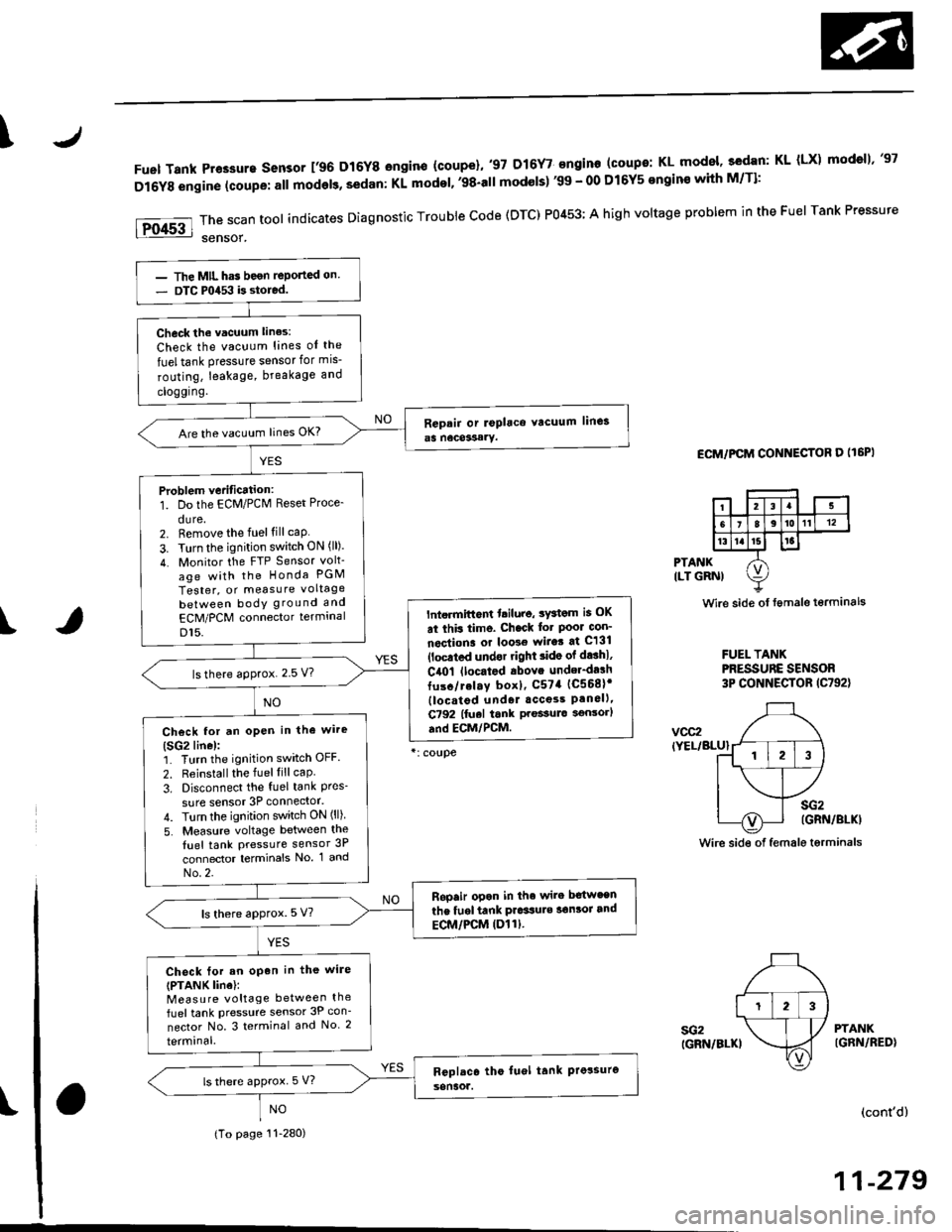
rFoG'l::;Jl"too|indicatesDiagnosticTroub|ecode(oTc)P0453;Ahighvo|tageprob|emintheFue|TankPressure
ECM/PCM CONNECTOR D Il6PI
PTANKILT GRNI
\
Wire side of tgmale torminals
FUEL TANKPRESSURE SENSOR3P CONNECTOR (C792)
vcc2(YEL/BLU}
sG2(GRN/BLKI
Wire sid€ of female terminals
I
sG2IGRN/BLKI
PTANKIGBN/RED}
(cont'd)
11-279
The MIL has beon reponed on
DTC P0453 b stored.
Check the vacuum lines:
Check the vacuum lines oI the
fueltank pressure sensor for mis-
routing, leakage, breakage and
clogging.
Are the vacuum lines OK?
Problem verification:1. Do the ECM/PCM Reset Proce-
dure.2. Femove the fuel fill cap
3. Turn the ignition switch oN (ll).
4. Monitor the FTP Sensor volt-
age with the Honda PGM
Tester, or measure voltage
between bodY ground and
ECM/PCM connector termrnal
D15.
lntormittont t iluro, 3Ystem is OK
at this time. Check lot Poor con_
noctiona or loo3e wirat at C131
{loc.ted undor right 3id6 of d8hl,
CaOl llocatod rbov. under-dalh
fus6/relay boxl, C574 (C568lr
llocatod und6l accoss Pan6ll,C792 lfuel tank Preasulo aonlorl
end ECM/PCM.
ls there approx. 2 5 V?
Check for an oPen in the wire(SG2line):1. Turn the ignition switch OFF.
2. Reinstall the fuellill cap
3. Disconnect the fuel tank Pres-sure sensor 3P connector.
4. Turn the ignition switch ON (ll)
5. Measure voltage between the
fuel tank Pressure sensor 3P
connector terminals No. 1 and
No.2.
Ropair opon in the wira b€tw€sn
the fuel tank prasure sonlor and
ECM/PCM (Dl1).ls there aPProx. 5 V?
Check for an open in the wire(PTANK line):Measure voltage between the
fueltank Pressure sensor 3P con-
nector No. 3 terminal and No. 2
termrnal,
ls there approx. 5 V?
*: coupe
{To page 11-280)
Page 552 of 2189
\
t,96 D16Y8 engine (coup6l,'9? Dl6Y7 engine (coupe: KL model, sedan: KL (LX) model)"g7 Dl6Y8 ongine (coupe: all mod-
els, sedan: KL model,'98-8ll modelsl 39 - 00 Dl5Y5 engine with M/Tl:
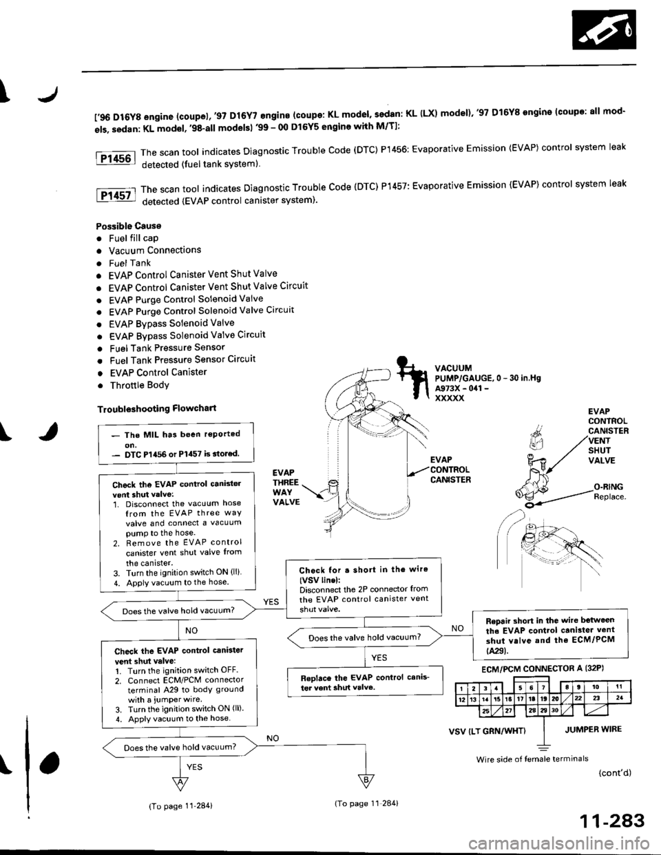
The scan tool indicates Diagnostic Trouble code (DTc) P1456: Evaporative Emission (EVAP) control system leak
detected (fuel tank sYsteml
The scan tool indicates Diagnostic Trouble Code (DTC) P1457: Evaporative Emission (EVAP) control system leak
detected (EVAP control canister system).
Fr4t6l
fF14s7
Possible Causs
. Fuel fill cap
. Vacuum Connections
. Fuel Tank
. EVAP Control Canister Vent Shut Valve
. EVAP Control Canister Vent Shut Valve Circuit
. EVAP Purge Control Solenoid Valve
. EVAP Purge Control Solenoid Valve Circuit
. EVAP Bypass Solenoid Valve
. EVAP Bypass Solenoid Valve Circuit
. Fuel Tank Pressure Sensor
. Fuel Tank Pressure Sensor Circuit
. EVAP Control Canister
. Throttle Body
Troublsshooting Flowchart
VACUUMPUMP/GAUGE,0 - 30 in.HgA973X - 041 -
xxxxx
I
EVAPCONTROL
.4, cANrsrER
re ./ VALVE
{S----r*::n
\(cont'd)
- The MIL ha3 been rePofted
on.- DTC P1456 or P1457 is stored.
Check the EVAP control canbtol
vent shut valve:1. Disconnect the vacuum hose
Irom the EVAP three waY
valve and connect a vacuurnpump to the hose.
2. Remove the EVAP control
canister vent shut valve Irofi
the canrster.3. Turn the ignition switch ON (lli
4. Apply vacuum to the hose.
Chock for . shon in the wire(VSv linel:Disconnect the 2P connector {rom
the EVAP control canister vent
Does the valve hold vacuum?
Repair short in the wir€ betwcen
the EVAP control canister vent
shut v.lve and tho ECM/PCM
tA29|.
Does the valve hold vacuum?
Check the EVAP control canister
vent shui valve:1. Turn the ignition switch OFF.
2. Connect ECM/PCM connectorterminal A29 to body ground
with a iumPer wire.
3. Turn the ignition switch ON (ll).
4. Applyvacuum to the hose
Reohce the EVAP control canis-
ter vent shttt valve.
Does the valve hold vacuum?
ECM/PCM CONNECTOR A {32P)
37I9t01t't2t3t5t6ItItt9202a2a
25aA
ILT GRN/W{T) I JUMPER WIRE
Wire side of femll terminals
(To page 11-284i(To page 11 284)
11-283
Page 563 of 2189
Emission Control System
Evaporative Emission (EVAPI Controls (cont'd)
Evaporative Emission (EVAPI Two Way Valve Testing
l'96 DIGYS engine lcoupel,'97 Dl6Y7 engine (coupe: KL
model, sedan: KL (LX) modoll,'97 Dl6Y8 engine {coup€:
alt models, sedan: KL model, '98-all modelsll:
1. Remove the fuel fill cap.
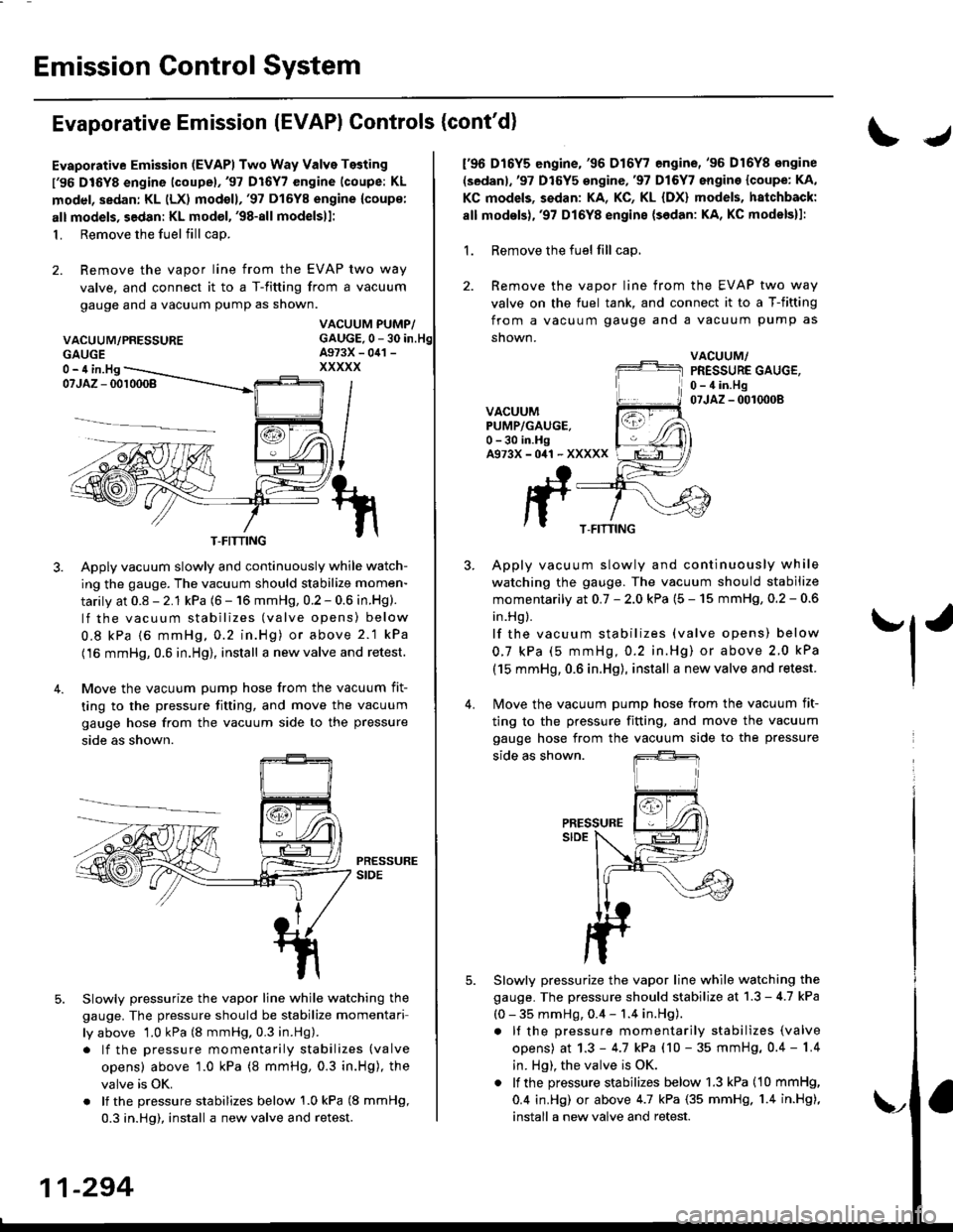
2. Remove the vapor line from the EVAP two way
valve. and connect it to a T-fitting from a vacuum
gauge and a vacuum pump as shown.
VACUUM/PRESSURE
IJ
f96 D16Y5 engine,'96 D16Y7 engine,'96 D16Y8 ongine
(sedanl,'97 D16Y5 engine,'97 Dl6Y7 engine {coupe: KA,
KC models, sedan: KA, KC, KL {DX} models, hatchback:
all modsls),'97 D16Y8 engine {sedan: KA, KC models}l:
1. Remove the fuel fill cap,
2. Remove the vapor line from the EVAP two way
valve on the fuel tank, and connect it to a T-fitting
from a vacuum gauge and a vacuum pump as
snown.
VACUUM/PRESSURE GAUGE,0 - 4 in.Hg07JAZ - 0010008VACUUMPUMP/GAUGE.0 -30 in.HgA973X-041 -XXXXX
Apply vacuum slowly and continuously while watch-
ing the gauge. The vacuum should stabilize momen-
tarily at 0.8 - 2.1 kPa (6 - 16 mmHg, 0.2 - 0.6 in.Hg).
lf the vacuum stabilizes (valve opens) below
0.8 kPa {6 mmHg, 0.2 in.Hg) or above 2.1 kPa
(16 mmHg, 0.6 in.Hg), install a new valve and retest.
Move the vacuum pump hose from the vacuum fit-
ting to the pressure fitting, and move the vacuum
gauge hose from the vacuum side to the pressure
side as shown.
Slowlv pressurize the vapor line while watching the
gauge. The pressure should be stabilize momentari
ly above 1.0 kPa (8 mmHg. 0.3 in.Hg).
. lf the pressure momentarily stabilizes (valve
opens) above '1.0 kPa (8 mmHg, 0.3 in.Hg), the
valve is OK.
. lf the pressure stabilizes below 1.0 kPa (8 mmHg,
0.3 in.Hg), install a new valve and retest.
Apply vacuum slowly and continuously while
watching the gauge. The vacuum should stabilize
momentarily at 0.7 - 2.0 kPa (5 - 15 mmHg, 0.2 - 0.6
in.Hg ).
lf the vacuum stabilizes (valve opens) below
0.7 kPa (5 mmHg,0.2 in.Hg) or above 2.0 kPa
(15 mmHg, 0.6 in.Hg), install a new valve and retest.
Move the vacuum pump hose from the vacuum fit-
'l'
4.
5.
ting to the pressure fitting, and move the
gauge hose from the vacuum side to the
side as shown.
PRESSURESIDE
Slowly pressurize the vapor line while watching the
gauge. The pressure should stabilize at 1.3 - 4.7 kPa
(0 - 35 mmHg, 0.4 - 1.4 in.Hg).
. It the pressure momentarily stabilizes (valve
opens) at 1.3 - 4.7 kPa (10 - 35 mmHg, 0.4 - 1.4
in. Hg), the valve is OK.
. lf the pressure stabilizes below 1.3 kPa (10 mmHg,
0.4 in.Hg) or above 4.7 kPa (35 mmHg. 1.4 in.Hg),
install a new valve and retest.
vacuum
pressure
GAUGE0- 4 in.Hg
T-FITTINGT-FITTING
11-294
\,
Page 586 of 2189
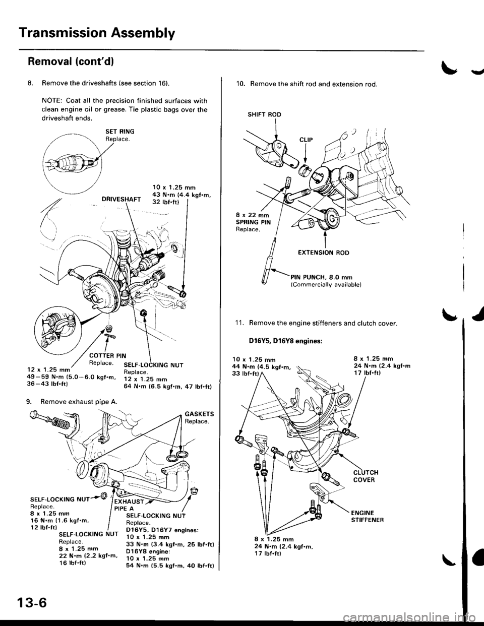
Transmission Assembly
Removal (cont'dl
8. Remove the driveshafts (see section 161.
NOTE: Coat all the precision finished surfaces with
clean engine oil or grease. Tie plastic bags over the
driveshaft ends,
DRIVESHAFT
10 x 1.25 mrn43 N.m 14.4 kgt.m,32 rbf.frl
COTTER PINReplace. SELF12 x 1.25 mm49-59 N.m (5.0 -6.0 kgt.m,36-43 lbf.ft)
9. Remove exhaust pipe A.
Replace.12 x 1.25 mm64 N.m {6.5 kgt.m,47 lbf.tr)
GASKETSReplace.
IF\sELF-LocKtNG NUT.''1/Replace.8 x 1.25 mm16 N.m {1.6 kgf'm,12 tbf.ft)
EXHAUSTPIPE A
SELF-LOCKING NUTReplace.I x 1.25 mm22 N.m (2.2 kgf.m,16 tbt'fr)
SELF-LOCKING NUTReplace.D16Y5, D16Y7 engines:
33 N.m {3.4 kgf.m,25 lbt.ft)D16YB engine:10 x 1.25 mm54 N.m 15.5 kgl'm,40 lbf.ttl
SET RING
13-6
v'10. Remove the shift rod and extension rod.
SI'IIFT BOD
8x22mmSPRING PINReplace.
EXTENSION ROD
PIN PUNCH, 8.O mm(Commercially available)f-
'1'1. Remove the engine stiffeners and clutch cover.
D16Y5, D16Y8 engines:
10 x 1.25 mm44 N.m (4.5 kgt.m,33 tbf.tr)
I x 1.25 mm24 N.m (2.4 kgf.m17 lbt.frl
COVER
8 x 1.25 mm24 N.m 12.4 kgf'tn,17 tbt.tr)
Page 587 of 2189
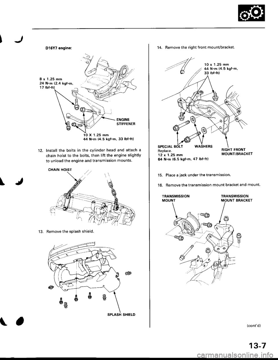
12.
D16Y7 engine:
ENGINESTIFFENER
10 X 1.25 mmIt4 N'm (4.5 kqf'm,33 lbf'ltl
Install the bolts in the cylinder head and attach a
chain hoist to the bolts, then lift the engine slightly
to unload the engine and transmission mounts.
CHAIN HOIST
13. Remove the sDlash shield,
\
8 x 1.25 mm24 N.m {2.4 kgl.m,
SPLASH SHIELD
14. Remove the right front mounvbracket.
'lO x 'l.25 mm44 N'm (4.5 kgl.m,33 rbf.frl
Replace.12 x 1.25 mm
64 N.m t6.5 kgf.m,47 lbf'ft)
Place a jack under the transmission.
Remove the transmission mount bracket and mount.16.
TRANSMISSIONMOUNTTRANSMISSIONBRACKET
(cont'd)
13-7
Page 591 of 2189
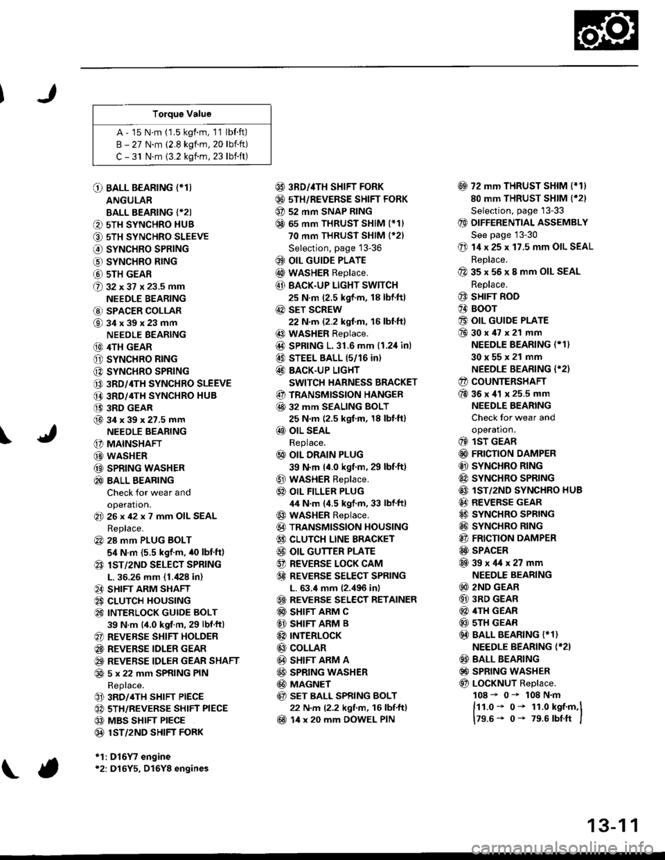
Torque Value
A - 15 N.m (1.5 kgf.m, 1'1 lbf.ft)
B - 27 N.m (2.8 kgf.m. 20 lbift)
C - 31 N.m {3.2 kgnm, 23 lbift)
\
O BALL BEARING (*T)
ANGULAR
BALL BEARING {*2I
O 5TH SYNCHRO HUB
O 5TH SYNCHRO SLEEVE
€) SYNCHRO SPRING
o SYNCHRO B|NG
@ 5TH GEAR
@ gz xgt x 23.5 mm
NEEDLE BEARING
@ SPACER COLLAR
@34x39x23mm
NEEDLE BEARING
(D 4TH GEAR
O SYNCHRO RING
C) SYNCHRO SPRING
CO 3RD/4TH SYNCHRO SLEEVE
@ 3RD/4TH SYNCHRO HUB
(} 3RD GEAR
@34x39x27.5mmNEEDLE BEARING
G) MAINSHAFT
G) WASHER
@ SPRING WASHER
@ BALL BEARING
Check for wear and
operation.(E 26x42x7 mm OIL SEAL
Replace.
@ 28 mm PLUG BOLT
5,1 N.m {5.5 kgf'm, /t0 lbt'ft)
@ lsT/zND SELECT SPRING
L. 36.26 mm (1./P8 in)
@ SHIFT ARM SHAFT
@ CLUTCH HOUSING
@ INTEELOCK GUIDE BOLT
39 N.m (4.0 kgf.m, 29 lbf.ftl
@ REVERSE SHIFT HOLDER
@ REVERSE IDLER GEAR
@ REVERSE IDLER GEAR SHAFT
@ 5 x 22 mm SPRING PIN
Replace.
@ 3RD/4TH SHIFT PIECE
@ 5TH/REVERSE SHIFT PIECE
@ MBS SHIFT PIECE
@ 1ST/2ND SHIFI FORK
*1:D16Y7 engine*2: D16Y5, D16Y8 engines
@ 3RD//|TH SHIFT FORK
@ 5TH/REVERSE SHIFT FORK
@ 52 mm SNAP RING
@ 65 mm THRUST SHIM (*11
70 mm THRUST SHIM (*21
Selection, page 13-36
@ OIL GUIDE PLATE
@ wASHER Replace.
@ BACK.UP LIGHT SWITCH
25 N.m (2.5 kgf'm, 18 lbf'ft)
@ sET SCREW
22 N.m {2.2 kgf.m, 16 lbl.ft}
@ WASHER Replace.
@D SPRING 1.31.6 mm (1.2,1inl
@ STEEL BALL 15/16 in)
@ BACK-UP LIGHT
SWITCH HARNESS BRACKET
@ TRANSMISSION HANGER
@ 32 MM SEALING BOLT
25 N.m (2.5 kgf.m, 18 lbt'ft)
@ OIL SEAL
Replace.
@ OIL DRAIN PLUG
39 N.m (4.0 kgf.m, 29 lbf.ft)
@ WASHER Replace.
@} OIL FILLER PLUG
44 N.m (4.5 kgf.m, 33 lbf'ftl
@ WASHER Replace.
@) TRANSMISSION HOUSING
€) CLUTCH LINE BRACKET
@ OIL GUTTER PLATE
@ REVERSE LOCK CAM
@ REVEBSE SELECT SPRING
L. 63.4 mm {2.,196 in)
@ REVERSE SELECT RETAINER
@ SHIFT ARM C
@ SHIFT ARM B
@ INTERLoCK
@ COLLAR
@ SHIFT ARM A
@ SPRING WASHER
@ MAGNET
@ sET BALL SPRING BOLT
22 N.m (2.2 kgf.m, 16 lbf.ftl
@ 14 x 20 mm DOWEL PIN
@ 72 mm THRUST SHIM l*11
80 mm THRUST SHIM (*21
Selection, page '13-33
@ DIFFERENTIAL ASSEMBLY
See page 13-30
@ 14 x 25 x 17.5 mm OIL SEAL
Replace.
@ 35 x 56 x 8 mm OIL SEAL
Replace.
@ SHIFT ROD
@ BOOr
@ OIL GUIDE PLATE
@30x47x21 mm
NEEDLE BEARING (* 1}
30x55x21 mm
NEEDLE BEARING {'2)
@ COUNTERSHAFT
@36x41 x 25.5 mm
NEEDLE BEARING
Check for wear and
operatron.
@ lsT GEAR
@ FRICTION DAMPER
@ SYNCHRO RING
@ SYNCHRO SPRTNG
@ lST/2ND SYNCHRO HUB
@ REVERSE GEAR
@ SYNCHRO SPRING
@ SYNCHRO RING
@ FRICTION DAMPER
@ SPACER
@39x4lx27mm
NEEDLE BEARING
@ 2ND GEAR
@ 3RD GEAR
@ 4TH GEAR
@ sTH GEAR
@) BALL BEARING {* 1}
NEEDLE BEARING (*2}
@ BALL BEARING
@) SPRING WASHER
@ LoCKNUT Replace.
108 - 0- 108 N.m
ftt.o* o- 1r.o kst.m,l
179.6- 0- 79.6 rbtft I
13-1 1
Page 595 of 2189
Mainshaft Assembly
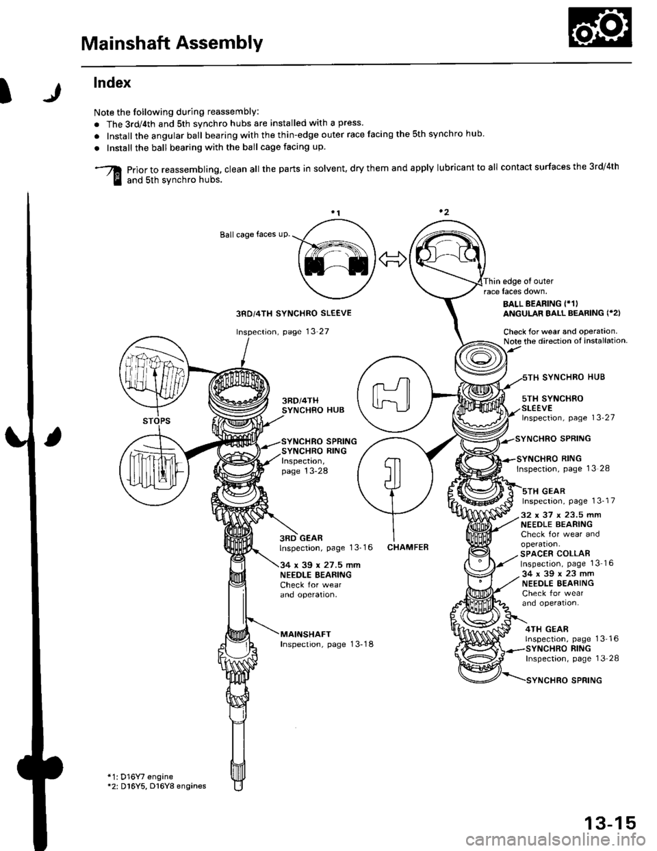
I
lndex
Note the following during reassembly:
. The 3rd/4th and sth svnchro hubs are installed with a press
. Install the angular ball bearing with the thin-edge outer race facing the sth synchro hub
. Install the ball bearing with the ball cage facing up
prior to reassembling, clean all the parts in solvent, dry them and apply lubricant to all contact surfaces the 3rd/4th
and sth svnchro hubs.
Ballcage faces uP.
Thin edge of outerrace laces down.
3RD/4TH SYNCHRO SLEEVE
page 13'27
SYNCHRO SPRINGSYNCHRO RINGInspection,page 13-28
BALL BEARING {*1)ANGULAR BALL BEARING ('2)
Check for wear and operataon.Note the direction ot installation
5TH SYNCHROSLEEVElnspection, page 13-27
SYNCHRO HUB
SYNCHRO RINGInspection, pase 13 28
sTH GEARInspection, page 13-17
3RD GEARlnspection, page 1 3-1 6
34 x 39 x 27.5 mmNEEDLE BEARINGCheck for wearano opetaflon,
MAINSHAFTInspection, page 13-18
CHAMFEB
32 x 37 x 23.5 mmNEEDLE BEARINGCheck for wear andoperation.SPACER COLLABInspection, page 1316
34x39x23mmNEEDLE EEARINGCheck for wearand operation,
4TH GEARrnspeclron,
*1: D16Y7 engine*2: D16Y5, D16Y8 engines
page 13'16RINGInspectaon, page 13 28
SPRING
13-15
Page 599 of 2189
I
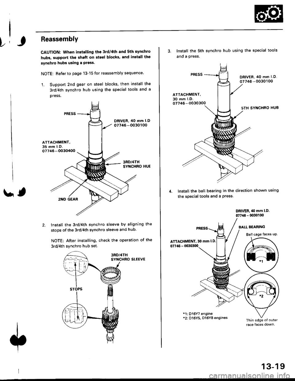
)r'
Reassembly
CAUTION: When installing the 3rd/4th and 5th synchro
hubs, support th€ shaft on steel blocks, and insiall the
synchro hubs using a press.
NOTE: Refer to page 13-15 for reassembly sequence.
1. Support 2nd gear on steel blocks' then install the
3rd/4th synchro hub using the special tools and a
oress.
ATTACHMENT,35 mm LO.07746-OO3O/+OO
' ,2I{D GEAR
Install the 3rd/4th synchro sleeve by aligning the
stops of the 3rdl4th synchro sleeve and hub.
NOTE; After installing, check the operation of the
3rd/4th svnchro hub set
SYf{CHRO SLEEVE
3. Install the sth
ano a press.
synchro hub using the special tools
DRIV€R, 40 mm I O.
07746 -0030'�100
ATTACHMENT,30 mm l.D.07746 -O030300
sTH SYNCHRO HU8
Install the ball bearing in the direction shown using
the special tools and a Press.
DRIVER, iO mm l.D.
07746 - lxxlollx'
ATTAGHMENT, 30 mm l.D.
077i16 - 00303qt
BAI-L BEARING
Ball cage faces uP
*1: D16Yt engane*2: Dl6Y5, D16Y8 6ngines
13-19
Page 600 of 2189
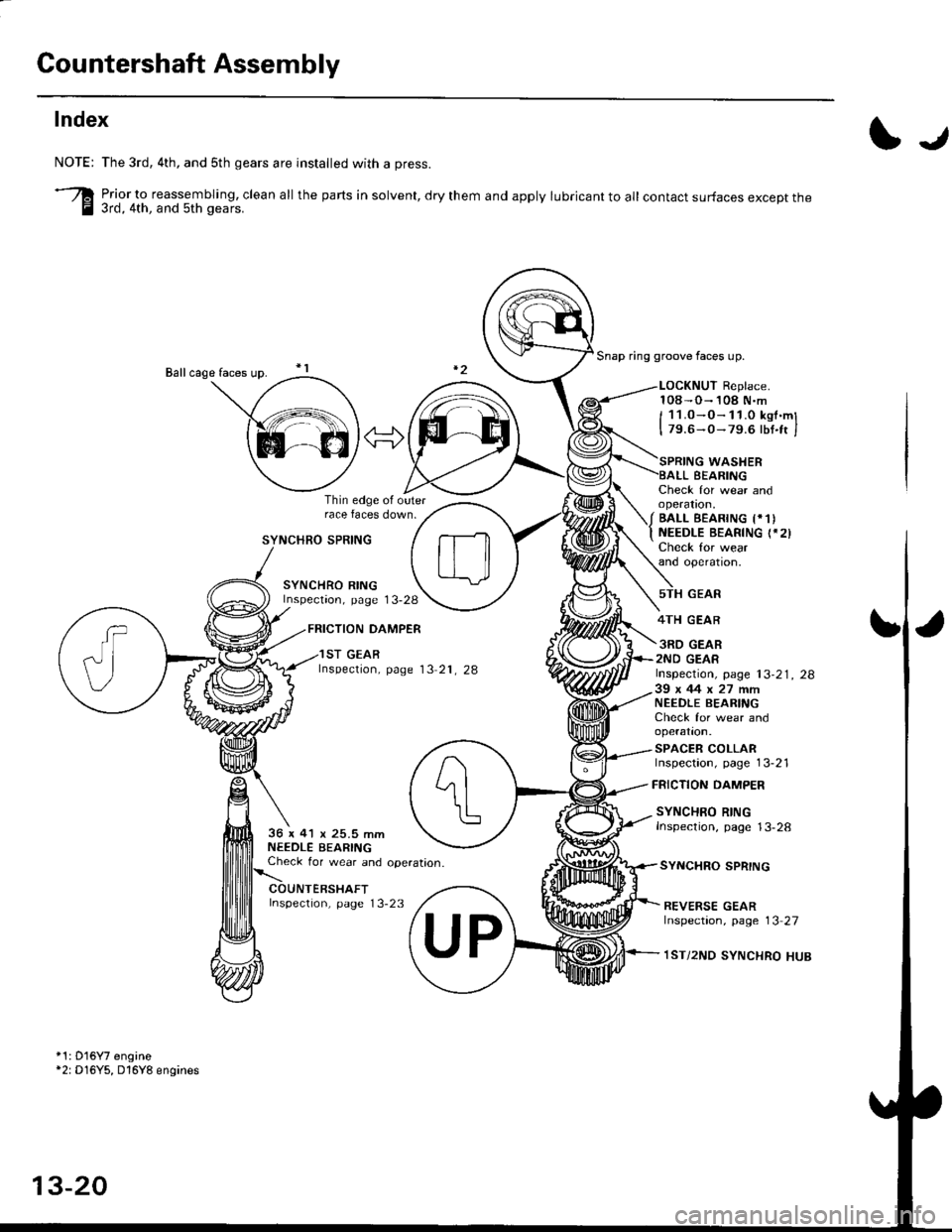
Countershaft Assembly
Index
I.r
NOTE:
-re
The 3rd, 4th, and sth gears are installed with a press.
Prior_to reassembling, clean all the parts in solvent, dry them and apply lubricant to all contact surfaces except the3rd, 4th, and 5th gears.
Snap ring groove faces up.
LOCKNUT Replace.108-O- 108 N.m
I 11.0-O-11.0 kst.ml
I 79.6-0- 79.6 lbt.ft I
SYNCHRO SPRING
SYNCHRO RINGInspectaon, page 13-28
FRICTION DAMPER
Thin edge ol outerrace faces down.
Check for wear andoperatron,
/ BALL EEAR|NG t*1)
t NEEDLE BEARTNG (.2)
Check for wearand operatron,
WASHERBEARING
GEAR
4TH GEAR
3RD GEAR2ND GEAR
FRICTION DAMPER
SYNCHRO SPRING
SYNCHRO RINGInspection, page 13-2836 x 41 x 25.5 mmNEEDLE BEARINGCheck for wear and operataon.
Inspection, page 13-23
1ST GEARlnspection, page 13 21, 28lnspection, page 13-21, 2839x44x27m�mNEEDLE BEARIfI'GCheck for wear andoperation.
SPACER COLLARInspection, page 13-21
REVERSE GEARlnspection, page 13 27
1ST/2ND SYNCHRO HUB
*1: D'16Y7 engine*2: D16Y5, D16Y8 engines
13-20