For HONDA CIVIC 1997 6.G Repair Manual
[x] Cancel search | Manufacturer: HONDA, Model Year: 1997, Model line: CIVIC, Model: HONDA CIVIC 1997 6.GPages: 2189, PDF Size: 69.39 MB
Page 128 of 2189
Timing Belt
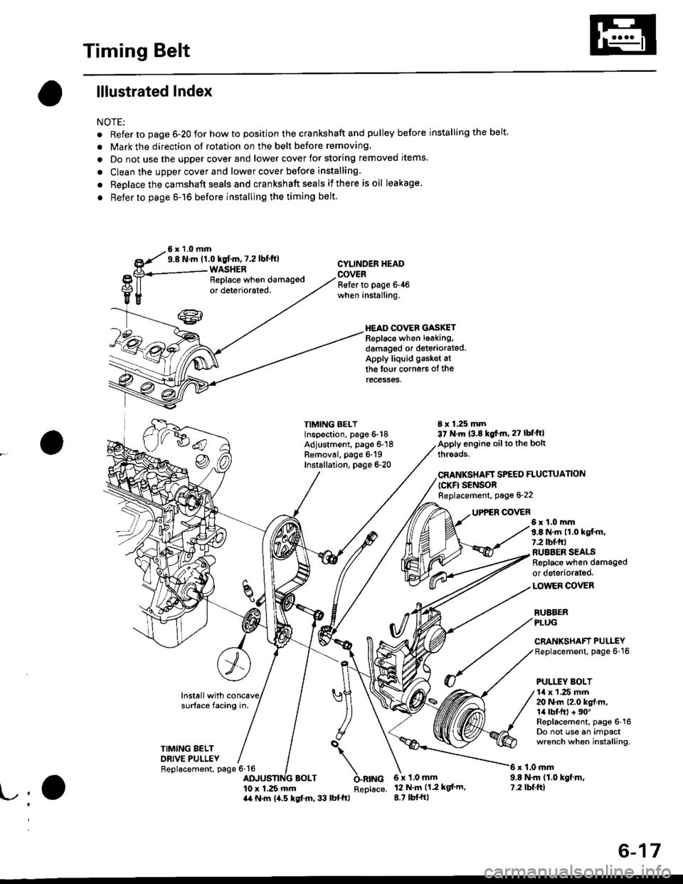
Illustrated lndex
NOTE:
. Refer to page 6-20 for how to position the crankshaft and pulley before installing the belt.
. Mark the direction of rotation on the belt before removing.
a Do not use the upper cover and lower cover for storing removed items,
. Clean the upper cover and lower cover before installing.
. Replace the ca mshaft seals and cra n kshaft sea ls if there is oil leakage.
. Refer to page 6-16 before installing the timing belt.
CYLINDER HEADCOVERReler to page 6-46when installing.
HEAD COVEB GASKETReplaco when l6akin9,domaged or deteriorated.Apply liquid gasket at
th€ lour corners of thetecessos.
d
@
TIMING BELTInspection, page 6-18Adjustment, page 6-18Removal, page 6-19Installation. page 6-20
I x 1.25 mm3t N.m {3.8 kgf'm, 27 lbfftl
Apply engine oilto the bolt
thleads.
CRANKSHAFT SPEED FI.UCTUATION
lcr(Fl sENsoRReplacement, Page 6-22
UPPER COVEB
lnstallwithsurface facing in.
TIMING BELTDRIVE PULLEYReplacement, page 6_16
6x1.0mm9.8 N'm 11.0 kgt m,7.2 tbf.ft)NUBBER SEALSReplace when damagedor deledorated.
LOWER COVER
FUBBERPLUG
CRANKSHAFT PULLEYReplacement, page 6'16
PULLEY BOLTlil x 1.25 mm20 N.m 12.0 kgt.m,14 lbt'ft) + 90"Replacement, page 6'16Do not us6 an impactwrench when installing.
x 1.0 mmBOLT o-RING10 x 1,25 mm Reolace.14 N.m {,1.5 kgt m, 33 lbt ftl
6x1.0mmt2 N.m 11.2 kgf'm,8.7 tbt f0
9.E N'm (1.0 kgt.m,?.2 tbf.ftl\.-,o
6-17
Page 129 of 2189
Timing Belt
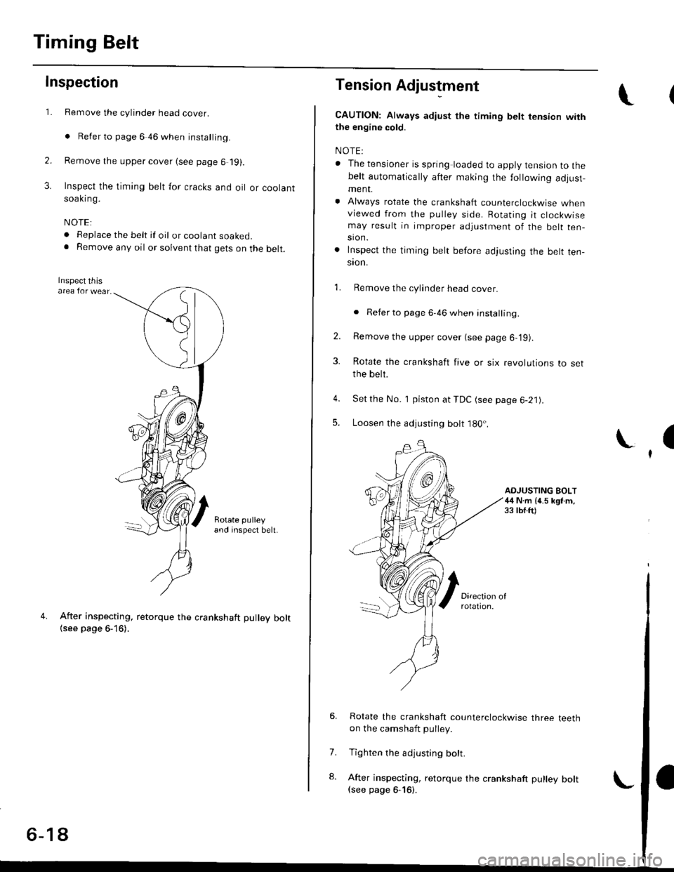
Inspection
1.
2.
3.
Remove the cylinder head cover.
. Refer to page 6 46 when installing.
Remove the upper cover (see page 6 19).
Inspect the timing belt for cracks and oil or coolantsoakrng.
NOTE:
. Replace the belt if oil or coolant soaKeo.. Remove any oil or solvent that gets on the belt.
Rotate pulleyand inspect belt.
After inspecting, retorque the crankshaft pullev bolt{see page 6- 16).
o- I6
Tension Adjustment
CAUTION: lt*ays aa;j"t the timing bett rension withthe engine cold.
NOTE:
. The tensioner is spring loaded to apply tension to thebelt automatically after making the following adjustment.
. Always rotate the crankshaft counterclockwise whenviewed from the pulley side. Rotating it clockwisemay result in improper adjustment of the belt ten-sion.
. lnspect the timing belt before adjusting the belt ten-ston.
1.Remove the cylinder head cover.
. Refer to page 6,46 when installing.
Remove the upper cover (see page 6,'19).
Rotate the crankshaft five or six revolutions to setthe belt.
Set the No. 'l piston at TDC (see page 6-21).
Loosen the adjusting bolt 180'.
2.
3.
4.
5.
\I
ADJUSTING BOLT44 N.m {4.5 kgt m,33 rbf.ft)
7.
8.
Rotate the crankshaft counterclockwise three teethon the camshaft pulley.
Tighten the adjusting bolt.
After inspecting, retorque the crankshaft pulley bolt(see page 6-16).
Page 130 of 2189
Removal
NOTE:
. Replace the timing belt at 105,000 miles (168.000 km)
according to the maintenance schedule (normal con-
ditions/severe conditions).
lf the vehicle is regularly driven in one or more of the
followlng conditions, replace the timing belt at 60.000
miles (U.S.A.) 100,000 km {Canada).
.In very high temperatures (over 110'F.43'C)
. In very low temperatures (under -20'F, -29"C)'
! Turn the crankshaft pulley so the No. 1 piston is at
top dead center (TDC) before removing the belt (see
page 6'21).
. Inspect the water pump before installing the timing
belt {see Page 10-14).
1. Remove the splash shield (see page 5-7).
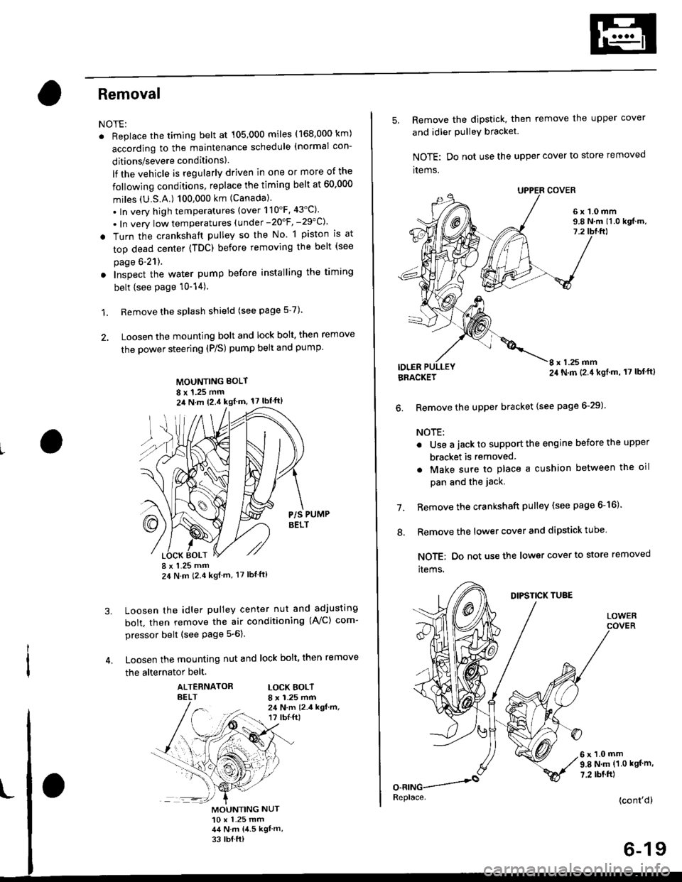
2. Loosen the mounting bolt and lock bolt. then remove
the power steering (P/S) pump belt and pump
MOUNTING BOLT
8 x 1.25 mm2il N m 12.4 kgl m, 17 lbf'ft)
P/S PUMPBELT
I x 1.25 mm24 N m (2.4 kgf m, 17 lbt ft)
Loosen the idler pulley center nut and adjusting
bolt, then remove the air conditioning (AVC) com-
pressor belt (see Page 5-6).
Loosen the mounting nut and lock bolt, then remove
the alternator belt.
ALTERNATORBELTLOCK BOLTI x 1.25 mm24 N.m 12.4 kgf.m,r? tbI.ft)
3.
MOUNTING NUT10 x 1.25 mm44 N.m 14.5 kgl m,
33 rb{ ft)
5. Remove the dipstick, then remove the upper cover
and idler PulleY bracket
NOTE: Do not use the upper cover to store removed
items.
6x1.0mm9.8 N.m 11.0 kgf.m,7.2
IDLERI x 1.25 mm24 N.m (2.4 kgl.m, 17 lbf'ft)BRACKET
6. Remove the upper bracket {see page 6-29)
NOTE:
. Use a jack to support the engine before the upper
bracket is removed
. Make sure to place a cushion between the oil
pan and the jack.
Remove the crankshaft pulley (see page 6-16).
Remove the lower cover and dipstick tube
NOTE; Do not use the lower cover to store removed
items.
1.
.'.
DIPSTICK TUBE
LOWER
6x1.0mm9.8 N.m (1.0 kgf m,
7.2 rbt.ft)
(cont'd)
6-19
Replace.
Page 132 of 2189
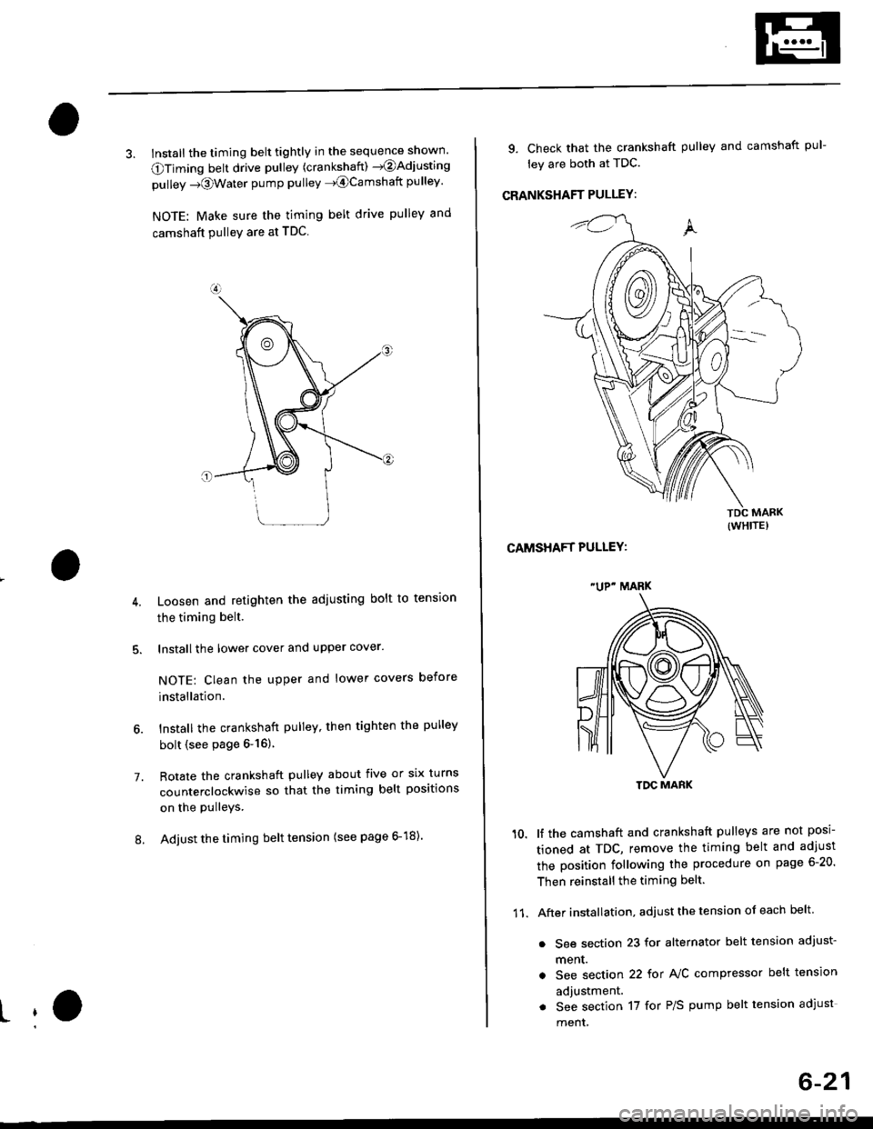
3. Install the timing belt tightly in the sequence shown'
OTiming belt drive pullev (crankshaft) )@Adjusting
pulley -towater pump pulley J@Camshatt pulley'
NOTE: Make sure the timing belt drive pulley and
camshaft PulleY are at TDC
7.
Loosen and retighten the adiusting bolt to tension
the timing belt.
lnstall the lower cover and upper cover.
NOTE: Clean the upper and lower covers before
installation.
lnstall the crankshaft pulley, then tighten the pulley
bolt (see page &16)
Rotate the crankshaft pulley about five or six turns
counterclockwise so that the timing belt positions
on the Pulleys.
Adjust the timing belt tension (see page 6-18).8.
L
9. Check that the crankshaft pulley and camshaft pul-
ley are both at TDC.
CRANKSHAFT PULLEY:
CAMSHAFT PULLEY:
lf the camshaft and crankshaft pulleys are not posi-
tioned at TDC, remove the timing belt and adjust
the position following the procedure on page 6-20'
Then reinstall the timing belt.
After installation, adjust the tension of each belt
. See section 23 for alternator belt tension adjust-
ment.
a See section 22 tot NC compressor belt tension
adjustment.
. See section 17 for P/S pump belt tension adjust
ment,
(wHrTE)
"UP" MARK
TDC MARK
11.
6-21
Page 134 of 2189
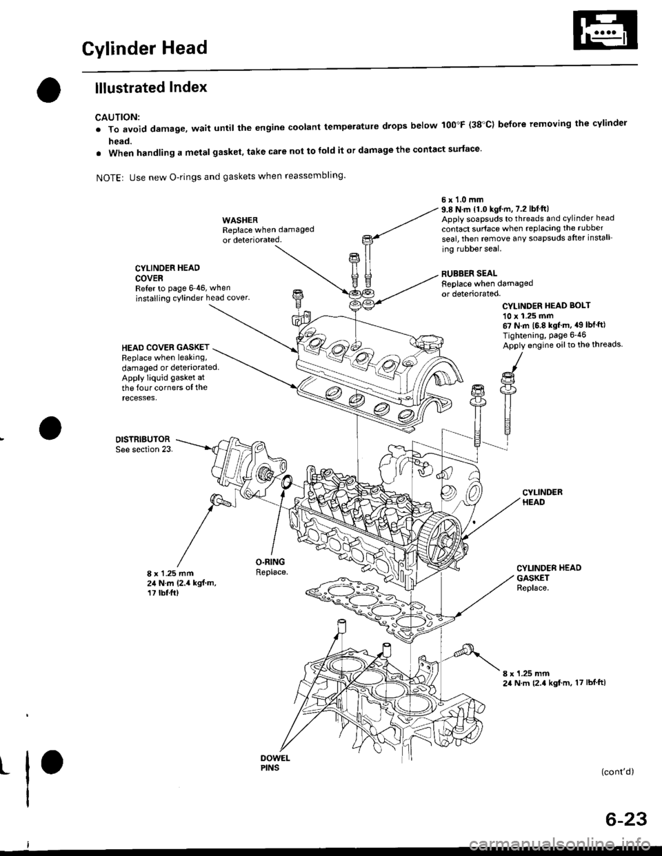
Gylinder Head
lllustrated Index
CAUTION:
. To avoid damage, wait until the engine coolant temperatule drops below 100"F (38'C) before removing the cylinder
head.
. When handling a metal gasket, take care not to fold it or damage the contact surface'
NOTEr Use new O-rings and gaskets when reassembling'
CYLINDER HEAD
COVERRefer to page 6 46, when
installing cylinder head cover.
WASHERReplace when damaged
or deteriorated.
O.RINGReplace.
6x1.0mm9.8 N.m 11.0 kgf.m, 7.2 lbfft)Apply soapsuds to threads and cylinder head
contact surface when replacing the rubber
seal, then temove any soapsuds after install
ing rubber seal.
RUBBER SEALReplace when damagedor deteriorated.
CYLINDER HEAD BOI-T
10 x 1.25 mm67 N.m 16.8 kgf m, a9 lbt'ft)
Tightening, Page 6-46
Apply engine oilto the threads.HEAD COVEB GASKETReplace when leaking,
damaged or deteriorated.Apply liquid gasket at
the four corners ol therecesses,
DISTRIBUTORSee section 23.
8 x 1 .25 mm24 N.m (2.4 kgf.m,17 tbt.ft)
CYLINDER HEADGASKETReplace.
8 x 1.25 mm24 N.m {2.4 kgf m, 17 lbf ftl
t(cont'd)
6-23
PINS
Page 138 of 2189
Removal
Engine removal is not required for this procedure
!!!s@ Make sure iacks and salety stands are
f ta"eata"ea propetty and hoist brackets are attached to the
correct positions on the engine.
CAUTION:
. Use tender covels to avoid damaging painted sul-
faces.
o To avoid damage, unplug the wiling connectors
carefully while holding the connector portion to
avoid damage.
. To avoid damaging the cylinder head, wait until the
engine coolant temperature drops below 100"F
{38"C} before loossning the tetaining bolts.
NOTE:
o Mark all wiring and hoses to avoid misconnectlon
Also, be sure that they do not contact other wiring or
hoses, or interfere with other parts.
. Inspect the timing belt before removing the cylinder
h ead.
. Turnthe crankshaft pu lley so that the No. lpistonisat
top dead center (see Page 6-21)
'1. Disconnect the negative terminal from the battery'
Drain the engine coolant (see page'10-7).
a Remove the radiator cap to speed draining.
Remove the intake air duct and air cleaner housing
(see page 5 3).
Remove the mounting bolt and lock bolt. then
remove the power steering (P/S) pump belt and
pump (see page 5'5).
Loosen the idler pulley center nut and adjusting
bolt' then remove the air conditioning (A'lc) com-
pressor belt (see Page 5-6).
Loosen the mounting nut and lock bolt. then
remove the alternator belt (see page 6-19).
Remove the P/S pump bracket (see page 5-12).
3.
4.
2.
6.
1.
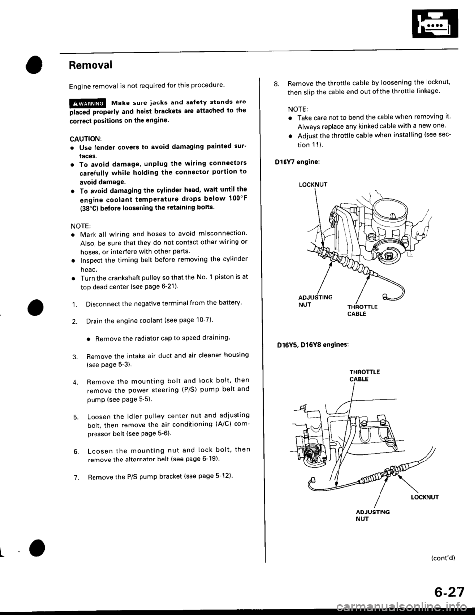
8. Remove the throttle cable by loosening the locknut,
then slip the cable end out of the throttle linkage
NOTE:
. Take care not to bend the cable when removing it
Always replace any kinked cable with a new one
. Adjust the throttle cable when installing (see sec-
tion 1 1).
D16Y7 engine:
Dl6Y5, Dl6Y8 engines:
THFOTTLECABLE
(cont'd)
6-27
LOCKNUT
CABLE
Page 140 of 2189
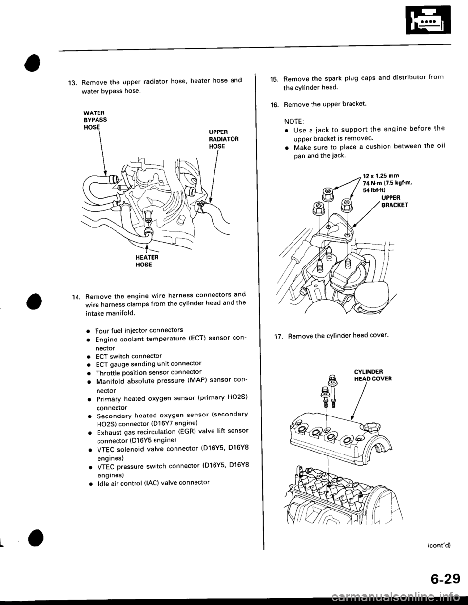
13. Remove the upper radiator hose' heater hose and
water bYPass hose
WATEREYPASSHOSEUPPERRADIATORHOSE
14.
HEATERHOSE
Remove the engine wire harness connectors and
wire harness clamps from the cylinder head and the
intake manifold.
o Four fuel injector connectors
. Engine coolant temperature (ECT) sensor con-
nector
a
a
a
ECT switch connector
ECT gauge sending unit connector
Throttle position sensor connector
Manitold absolute pressure (MAP) sensor con-
nector
Primary heated oxygen sensor (primary HO2S)
connector
Secondary heated oxygen sensor (secondary
HO2S) connector (D16Y7 engine)
Exhaust gas recirculation (EGR) valve lift sensor
connector (D16Y5 engine)
. VTEC solenoid valve connector (Dl6Y5, D16Y8
engrnes)
. VTEC pressure switch connector (D16Y5. D16Y8
engrnes,
. ldle air control (lAC) valve connector
15.Remove the spark plug caps and distributor from
the cylinder head.
Remove the uPPer bracket.
NOTE:
. Use a jack to support the engine before the
upper bracket is removed.
. Make sure to place a cushion between the oil
pan and the jack.
12 x 1.25 mm
74 N.m {7.5 kgf m.
sil lbl.ftl
UPPERBRACKET
'17. Remove the cylinder head cover'
CYLINDERHEAD COVER
(cont'd)
6-29
Page 146 of 2189
Rocker Arms and Shafts
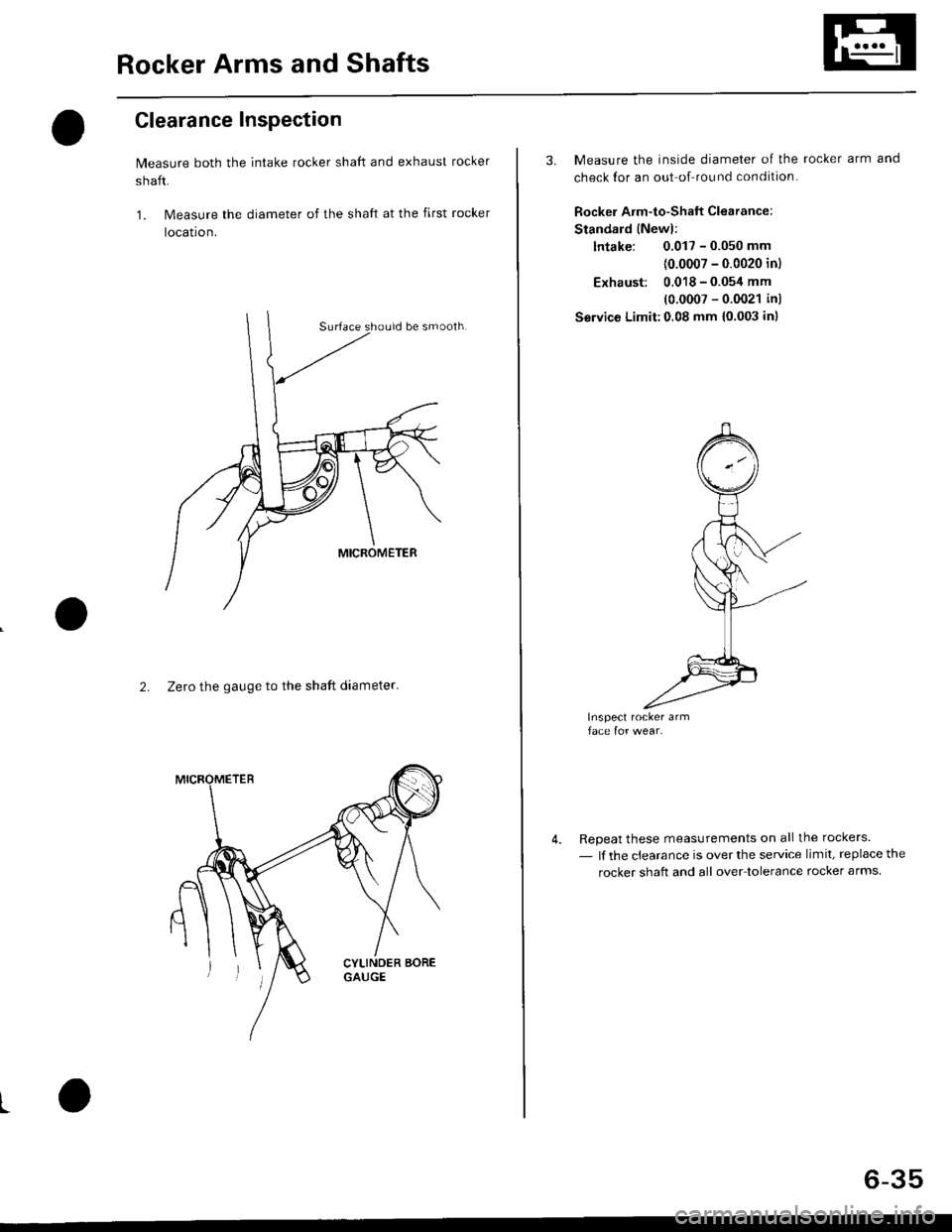
Clearance Inspection
Measure both the intake rocker shaft and exhaust rocker
shaft.
1. Measure the diameter of the shaft at the first rocker
locatron.
2. Zero the gauge to the shaft diameter'
I
3. Measure the inside diameter of the rocker arm and
check for an out of-round condition.
Rockel Arm-to-Shaft Clearance
Standard (Newl:
lntake: 0.017 - 0.050 mm
{0.0007 - 0.0020 inl
Exhaust: 0.018 - 0.054 mm
(0 0007 - 0 0021 in)
Service Limit:0.08 mm {0.003 inl
Repeat these measurements on all the rockers.
- lf the clearance is over the service limit, replace the
rocker shaft and all over tolerance rocker arms.
6-35
Page 149 of 2189
Valves, Valve Springs and Valve Seals
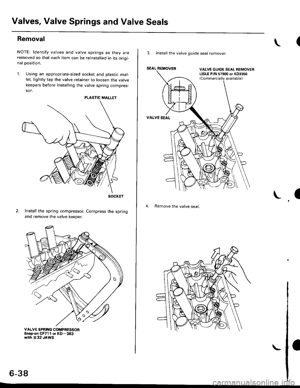
Removal
NOTE: ldentify valves and valve springs as they areremoved so that each item can be reinstalled in its orioi-nal oosition.
'1. Using an appropriate-sized socket and plastic mal-let. lightly tap the valve retainer to loosen the valve
keepers before installing the valve spring compres-
sor.
Install the spring compressor. Compress the spring
and remove the valve keeper.
PLASTIC MALLET
SOCKET
VALVE SPRII{G COMPRESSORSnlp-on CF711 or KD-383whh #32 JAWS
6-38
L
(
3. Install the valve guide seal remover.
SEAL REMOVER vat vF GI nF !
4. Remove the valve seal.
I
VALVE GUIDE SEAL REMOVERLISLE P/N 57900 or KD3350
Page 151 of 2189
Cylinder HeadValve Seats
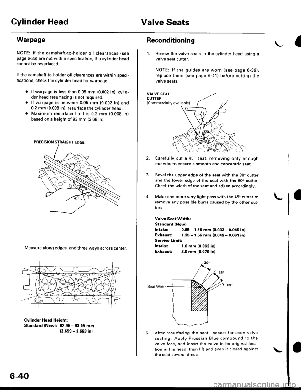
Warpage
NOTE: lf the camshaft-to-holder oil clearances (see
page 6-36) are not within specification, the cylinder head
cannot be resurfaced.
lf the camshaft-to-holder oil clearances are within sDeci,
fications, check the cylinder head lor warpage.
lf warpage is less than 0.05 mm (0.002 in), cylin-
der head resurfacing is not required.
lf warpage is between 0.05 mm (0.002 in) and
0.2 mm {0.008 in), resurface the cylinder head.
Maximum resurface limit is 0,2 mm (0.008 in)
based on a height of 93 mm (3.66 in).
Measure along edges, and three ways across center.
Cylinder Head Height:
Standard {Newl: 92.95 - 93.05 mm
{3.659 - 3.66:} in)
6-40
\
Reconditioning
'1. Renew the valve seats in the cylinder head using a
valve seat cutter.
NOTE: lf the guides are worn (see page 6-39).
replace them (see page 6-41) belore cutting the
valve seats.
VALVE SEATCUTTER(Commercially available)
2.
?
4.
Carefully cut a 45'seat, removing only enough
material to ensure a smooth and concentric seat.
Bevel the upper edge of the seat with the 30. cutter
and the lower edge of the seat with the 60' cutter.
Check the width of the seat and adjust accordingly.
Make one more very light pass with the 45" cutter to
remove any possible burrs caused by the other cut-
Iers.
Valve Seat Width:
Standard (N€w):
Intake: 0.85 - 1.15 mm 10.033 - 0.045 in)
Exhaust: 1.25 - 1.55 mm {0.049 - 0.061 in}
Sorvice Limit:
Intake: 1.6 mm (0.063 inl
Exhausl: 2.0 mm (0.079 in)
Seat Width
5. After resurfacing the seat, inspect for even valve
seatingr Apply Prussian Blue compound to the
valve face, and insert the valve in its original loca-
tion in the head, then liit and snap it closed against
the seat several times.