Connectors HONDA CIVIC 1997 6.G Workshop Manual
[x] Cancel search | Manufacturer: HONDA, Model Year: 1997, Model line: CIVIC, Model: HONDA CIVIC 1997 6.GPages: 2189, PDF Size: 69.39 MB
Page 37 of 2189
Llo
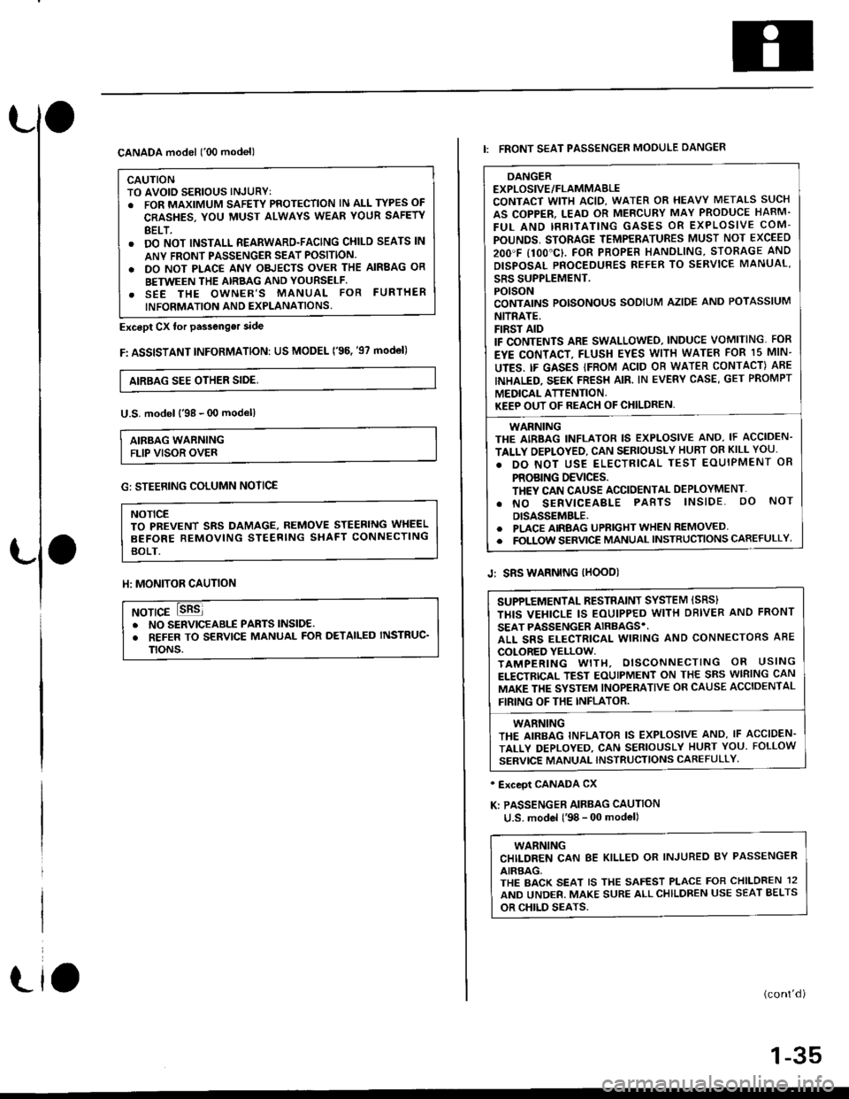
CANADA model ('00 model)
CAUTIONTO AVOID SERIOUS INJURYT. FOR MAXIMUM SAFETY PROTECTION lN ALL TYPES OF
CRASHES, YOU MUST ALWAYS WEAR YOUR SAFETY
BELT.. DO NOT INSTALL REARWARD-FACING CHILD SEATS lN
ANY FRONI PASSENGER SEAT POSITION.
. DO NOT PLACE ANY OBJECTS OVER THE AIRBAG OR
BETWEEN THE AIRBAG AND YOURSELF.. SEE THE OWNER'S MANUAL FOR FURTHER
INFORMATION AND EXPLANATIONS.
Except Cx tor passenger side
F: ASSISTANT INFoRMATION: US MODEL ('96. '97 mod€l)
AIRBAG SEE OTHER SIDE,
U.S. model l'98 - 00 modell
AIRBAG WARNINGFLIP VISOR OVER
Llo
G: STEERING COLUMN NOTICE
NOTICETO PBEVENT SRS DAMAGE, REMOVE STEERING WHEEL
BEFORE REMOVING STEERING SHAFT CONNECTING
BOLT.
ll: MONITOR CAUTION
NOTICE. NO SERVICEABIf PABTS lNSlDE.. REFER TO SERVICE MANUAL FOR DETAILED INSTRUC'
TtoNs.
DANGEREXPLOSIVE/FLAMMABLECONTACT WITH ACID, WATER OR HEAVY METALS SUCH
AS COPPER, LEAD OR MERCURY MAY PRODUCE HARM.
FUL AND IRRITATING GASES OR EXPLOSIVE COM-
POUNDS, STORAGE TEMPERATURES MUST NOT EXCEED
2OO'F I1OO"C}. FOR PROPER HANOLING, STORAGE AND
DISPOSAL PNOCEDURES REFER TO SERVICE MANUAL'
SRS SUPPLEMENT.POISONCONTAINS POISONOUS SODIUM AZIDE AND POTASSIUM
NITRATE.FIRST AIDIF CONTENTS ARE SWALLOWEO, INDUCE VOMITING. FOR
EYE CONTACT, FLUSH EYES WITH WATEB FOR 15 MIN-
UTES. IF GASES IFROM ACID OB WATER CONTACT) ABE
INHALED. SEEK FRESH AIR. IN EVERY CASE, GET PROMPT
MEDICAL ATTENTION.KEEP OUT OF REACH OF CHILDREN,
WARNINGTHE AIRBAG INFLATOR IS EXPLOSIVE AND, IF ACCIDEN-
TALLY OEPLOYED, CAN SERIOUSLY HUBT OR KILL YOU.
. DO NOT USE ELECTRICAL TEST EOUIPMENT OR
PROBING DEVICES.TH€Y CAN CAUSE ACCIDENTAL DEPLOYMENT'
. NO SERVICEABLE PABTS lNSlDE. oO NoT
DISASSEMBLE.. PLACE AIRBAG UPRIGHT WHEN REMOVED. FOLTOW SERVICE MANUAL INSTRUCTIONS CAREFULLY
I: FRONT SEAT PASSENGER MOOULE DANGER
Jr SRS WARNING IHOOD)
' Exceot CANADA CX
K: PASSENGER AIRBAG CAUTION
u.S. model l'98 - 00 model)
WARNINGCHILDREN CAN 8E KILLED OR INJUREO BY PASSENGER
AIRBAG,THE BACK SEAT IS THE SAFEST PLACE FOR CHILDREN 12
AND UNDER. MAKE SURE ALLCHILDREN USE SEAT BELTS
OR CHILD SEATS.
(cont'd)
1-35
SUPPLEMENTAL RESTRAINT SYSTEM ISRS}
THIS VEHICLE IS EOUIPPED WITH DBIVER AND FRONT
SEAT PASSENGER AIRBAGS'.ALL SRS ELECTRICAL WIRING AND CONNECTORS ABE
COLORED YELLOW.TAMPERING WITH, DISCONNECTING OR USING
ELECTRICAL TEST EOUIPMENT ON THE SRS WIRING CAN
MAKE THE SYSTEM INOPERATIVE OR CAUSE ACCIDENTAL
FIRING OF THE INFLATOR.
WARNINGTHE AIRBAG INFLATOR IS EXPLOSIVE AND, IF ACCIDEN.
TALLY DEPLOYED, CAN SERIOUSLY HURT YOU. FOLLOW
SERVICE MANUAL INSTRUCTIONS CAFEFULLY'
Page 96 of 2189
Engine RemovaUlnstallation
Removal
@@
1.
. Make sure iacks and salety stands are placed ploperly
and hoist brackets are attached to the correct posi-
tions on the engine.
. Make sure the vehicle will not roll off stands and fall
while you are working under it.
CAUTION:
. Use fender covers to avoid damaging painted sur-face.
. Unplug the wilin9 connectors caretully while holdingthe conngstor portion to avoid damage,. Mark all wiring and hosos to avoid misconnoction.
Also, be sure that they do not contact other wiring or
hoses or interfere with other parts,
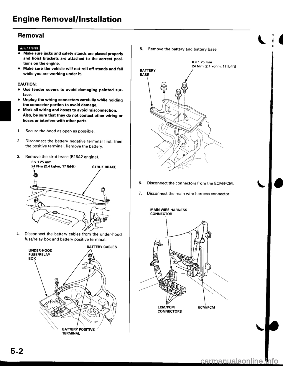
Secure the hood as open as possible.
Disconnect the battery negative terminal first. thenthe positive terminal. Remove the battery.
Remove the strut brace (B'16A2 engine).
8 x 1 .25 mm24 N.m {2.4 kgl.m, 17 lbf.ft}
Disconnect the battery cables from the under-hood
fuse/relay box and battery positive terminal.
STRUT BRACE
UNDER.HOODFUSE/RELAYBOX
BATTERY CABLES
5-2
ECM/PCM
(
5. Remove the battery and battery base.
8 x 1.25 mm24 N.m (2.4 kgf.m, 17 lbf ftl
7.
Disconnect the connectors from the ECM/pCM.
Disconnect the main wire harness connector.
MAIN WIRE HARNESSCONNECTOR
Page 99 of 2189
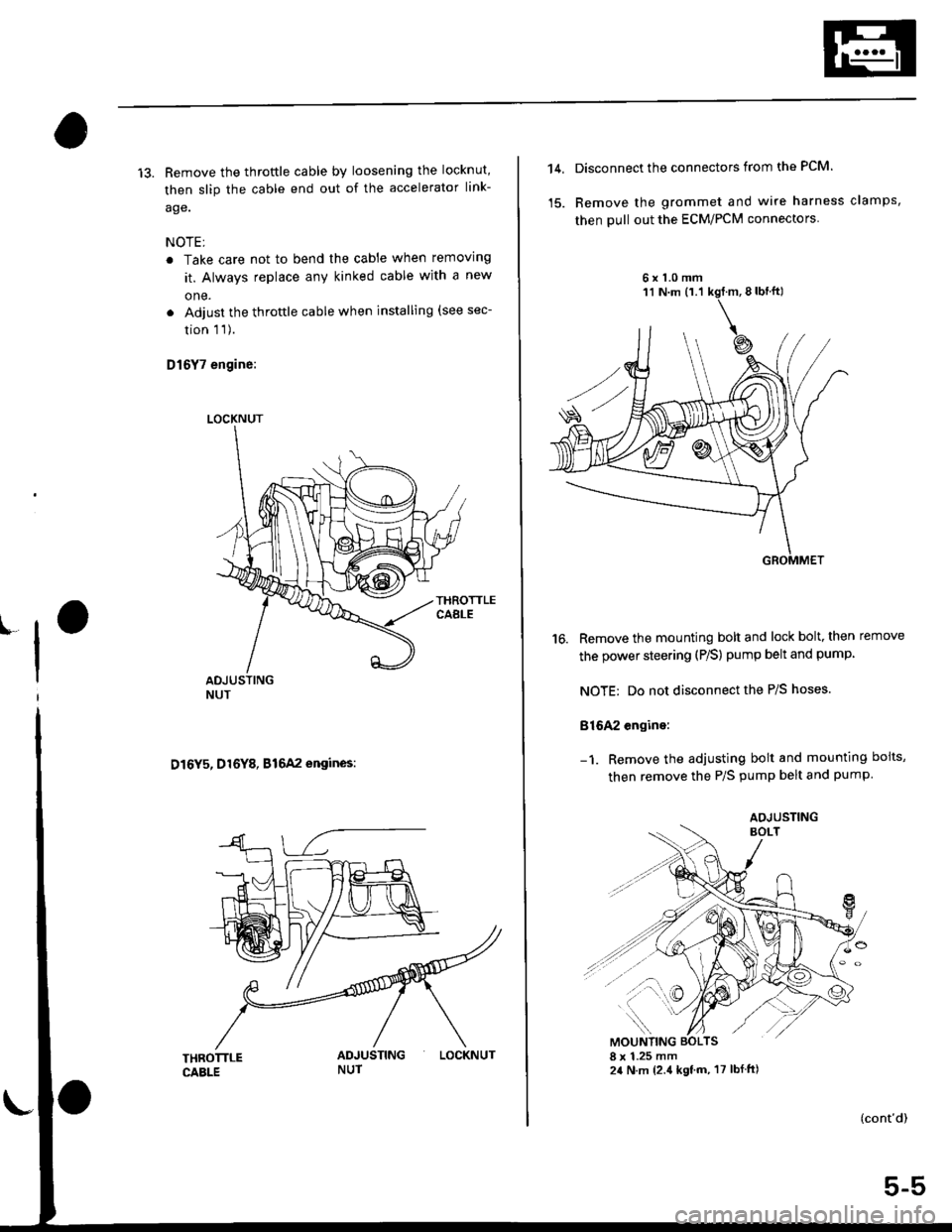
13. Remove the throftle cable by loosening the locknut,
then slip the cable end out of the accelerator link-
age.
NOTE;
. Take care not to bend the cable when removing
it. Always replace any kinked cable with a new
one.
. Adjust the throttle cable when installing (see sec-
tion 1 1).
D16Y7 engine:
D16Y5, D16Y8, B16A2 engines:
LOCKNUT
LOCKNUT
14,Disconnect the connectors from the PCM.
Remove the grommet and wire harness clamps,
then pull out the ECM/PCM connectors
6x1.0mm
16. Remove the mounting bolt and lock bolt, then remove
the power steering (P/S) pump belt and pump
NOTE: Do not disconnect the P/S hoses.
816A2 engine:
Remove the adjusting bolt and mounting boits,
then remove the P/S pump belt and pump
(cont'd)
5-5
AOJUSTING
Page 138 of 2189
Removal
Engine removal is not required for this procedure
!!!s@ Make sure iacks and salety stands are
f ta"eata"ea propetty and hoist brackets are attached to the
correct positions on the engine.
CAUTION:
. Use tender covels to avoid damaging painted sul-
faces.
o To avoid damage, unplug the wiling connectors
carefully while holding the connector portion to
avoid damage.
. To avoid damaging the cylinder head, wait until the
engine coolant temperature drops below 100"F
{38"C} before loossning the tetaining bolts.
NOTE:
o Mark all wiring and hoses to avoid misconnectlon
Also, be sure that they do not contact other wiring or
hoses, or interfere with other parts.
. Inspect the timing belt before removing the cylinder
h ead.
. Turnthe crankshaft pu lley so that the No. lpistonisat
top dead center (see Page 6-21)
'1. Disconnect the negative terminal from the battery'
Drain the engine coolant (see page'10-7).
a Remove the radiator cap to speed draining.
Remove the intake air duct and air cleaner housing
(see page 5 3).
Remove the mounting bolt and lock bolt. then
remove the power steering (P/S) pump belt and
pump (see page 5'5).
Loosen the idler pulley center nut and adjusting
bolt' then remove the air conditioning (A'lc) com-
pressor belt (see Page 5-6).
Loosen the mounting nut and lock bolt. then
remove the alternator belt (see page 6-19).
Remove the P/S pump bracket (see page 5-12).
3.
4.
2.
6.
1.
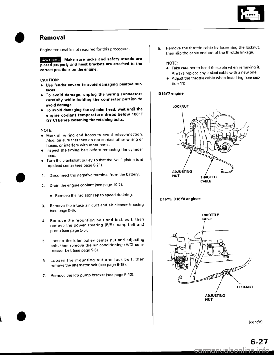
8. Remove the throttle cable by loosening the locknut,
then slip the cable end out of the throttle linkage
NOTE:
. Take care not to bend the cable when removing it
Always replace any kinked cable with a new one
. Adjust the throttle cable when installing (see sec-
tion 1 1).
D16Y7 engine:
Dl6Y5, Dl6Y8 engines:
THFOTTLECABLE
(cont'd)
6-27
LOCKNUT
CABLE
Page 140 of 2189
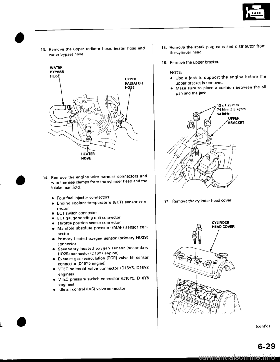
13. Remove the upper radiator hose' heater hose and
water bYPass hose
WATEREYPASSHOSEUPPERRADIATORHOSE
14.
HEATERHOSE
Remove the engine wire harness connectors and
wire harness clamps from the cylinder head and the
intake manifold.
o Four fuel injector connectors
. Engine coolant temperature (ECT) sensor con-
nector
a
a
a
ECT switch connector
ECT gauge sending unit connector
Throttle position sensor connector
Manitold absolute pressure (MAP) sensor con-
nector
Primary heated oxygen sensor (primary HO2S)
connector
Secondary heated oxygen sensor (secondary
HO2S) connector (D16Y7 engine)
Exhaust gas recirculation (EGR) valve lift sensor
connector (D16Y5 engine)
. VTEC solenoid valve connector (Dl6Y5, D16Y8
engrnes)
. VTEC pressure switch connector (D16Y5. D16Y8
engrnes,
. ldle air control (lAC) valve connector
15.Remove the spark plug caps and distributor from
the cylinder head.
Remove the uPPer bracket.
NOTE:
. Use a jack to support the engine before the
upper bracket is removed.
. Make sure to place a cushion between the oil
pan and the jack.
12 x 1.25 mm
74 N.m {7.5 kgf m.
sil lbl.ftl
UPPERBRACKET
'17. Remove the cylinder head cover'
CYLINDERHEAD COVER
(cont'd)
6-29
Page 158 of 2189
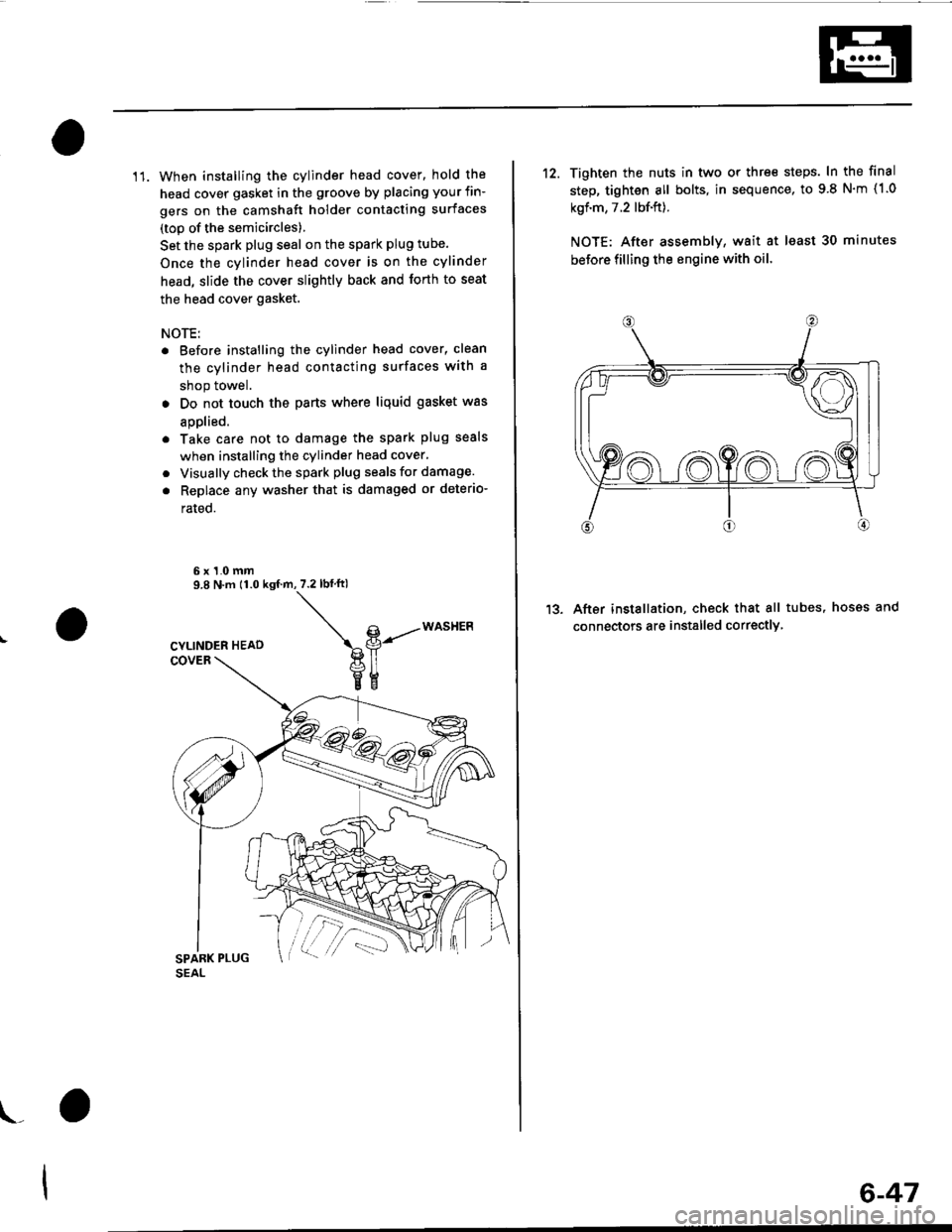
11. When installing the cylinder head cover, hold the
head cover gasket in the groove by placing your fin-
gers on the camshaft holder contacting surfaces
(top of the semicircles)
Set the spark plug seal on the spark plug tube.
Once the cylinder head cover is on the cylinder
head, slide the cover slightly back and forth to seat
the head cover gasket.
NOTE:
. Before installing the cylinder head cover, clean
the cylinder head contacting surfaces with a
shop towel.
. Do not touch the parts where liquid gasket was
aDolied.
. Take care not to damage the spark plug seals
when installing the cylinder head cover,
. Visually check the spark plug seals for damage.
. Replace any washer that is damaged or deterio-
rated.
6x1.0mm9.8 N.m 11.0 ksf.m,7.2lbf ftl
\g-----*o""t'Ptl
veEE
\_
6-47
12. Tighten the nuts in two or thre€ steps. In the final
step, tighten all bolts, in sequence, to 9 8 N'm (1.0
kgf.m, 7.2 lbf.ft).
NOTE: After assemblv, wait at least 30 minutes
before filling the engine with oil
After installation, check that all tubes, hosss and
connectors are installed correctlY
1?
Page 177 of 2189
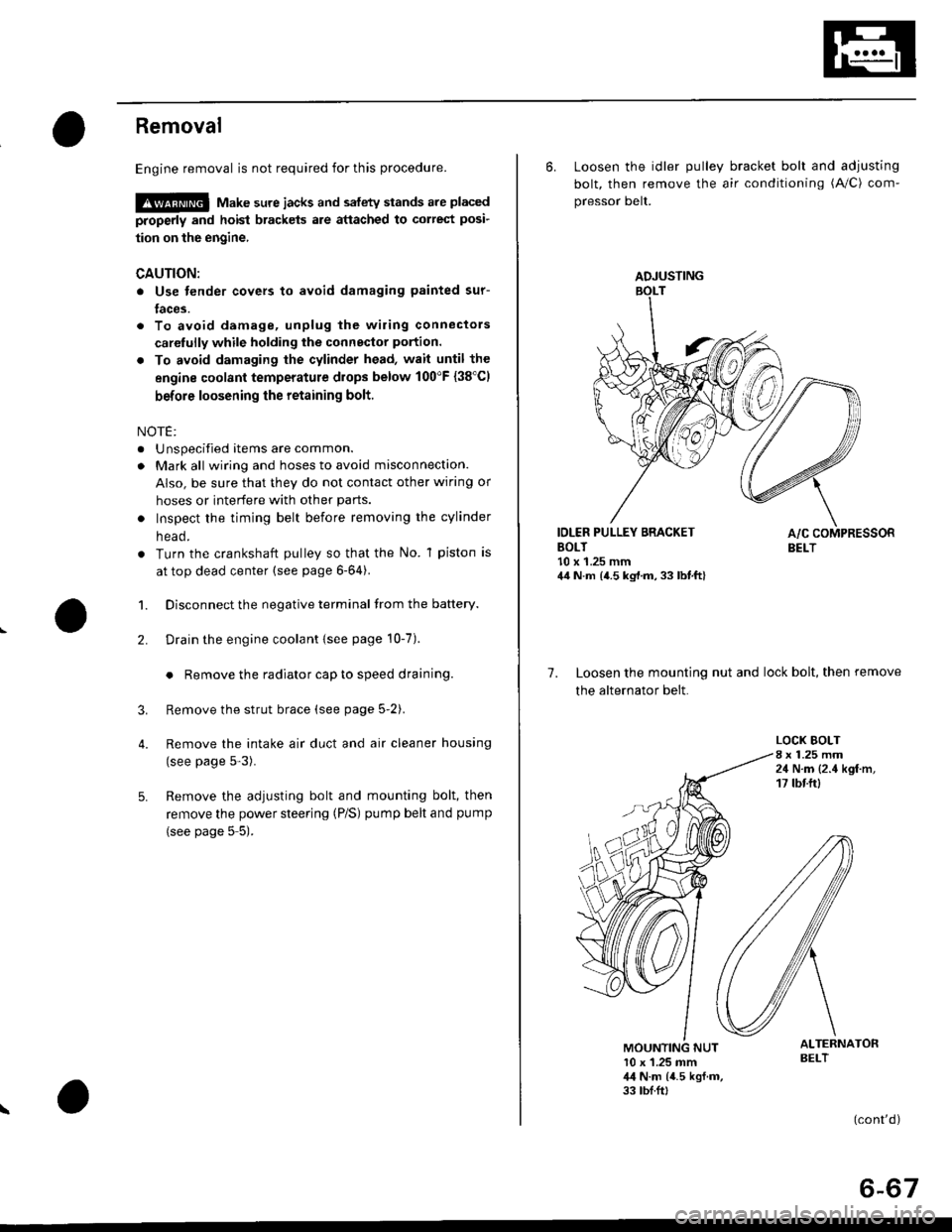
Removal
Engine removal is not required for this procedure.
!@@ Make sure jacks and safety stands are placed
properly and hoist brackels are attached to correst posi-
tion on the engine,
CAUTION:
o Use fender covers to avoid damaging painted sur-
faces.
To avoid damage, unplug the wiling connectors
carelully while holding the connector portion.
To avoid damaging the cylinder head, wait until the
engine coolant temperature drops below 100"F {38'Cl
before loosening the retaining bolt.
NOTE:
. Unspecified items are common.
. Mark all wiring and hoses to avoid misconnection.
AIso, be sure that they do not contact other wiring or
hoses or interfere with other parts.
o Inspect the timing belt before removing the cylinder
n eao.
. Turn the crankshaft pulley so that the No. 1 piston is
at top dead center (see page 6-64).
1. Disconnect the negative terminal from the battery.
Drain the engine coolant {see page 10-7).
. Remove the radiator cap to speed draining.
Remove the strut brace (see page 5-2).
Remove the intake air duct and air cleaner housing
(see page 5-3).
Remove the adjusting bolt and mounting bolt, then
remove the power steering (P/S) pump belt and pump
(see page 5 5).
2.
3.
4.
\
ADJUSTING
6. Loosen the idler pulley bracket bolt and adjusting
bolt, then remove the air conditioning (A/C) com-
pressor belt.
IDLER PULLEY BRACKETBOLT10 x 1.25 mm44 N.m {4.5 kg,l.m, 33 lbt.ft}
7. Loosen the mounting nut and lock bolt, then remove
the alternator belt.
LOCK BOLT8 x 1.25 mm24 N.m {2.4 kgf.m,17 tbtftl
ALTERNATORBELT10 x 1.25 mm,l,l N.m {4.5 kgf.m,33 tbf.ft,
(cont'd)
6-67
Page 179 of 2189
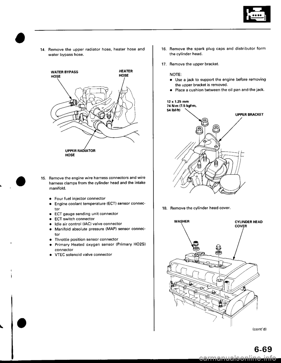
WATER BYPASS
HOSE
14. Remove the upper radiator hose, heater hose and
water bvpass hose.
HEATER
Remove the engine wire harness connectors and wlre
harness clamps from the cylinder head and the intake
manifold.
Four fuel injector connector
Engine coolant temperature (ECT) sensor connec-
tor
ECT gauge sending unit connector
ECT switch connector
ldle air control (lAC) valve connector
Manifold absolute pressure (MAP) sensor connec-
tor
Throttle position sensor connector
Primary Heated oxygen sensor (Primary HO2S)
connecror
VTEC solenoid valve connector
15.
a
a
a
a
a
\
16.
17.
Remove the spark plug caps and distributor form
the cylinder head.
Remove the upper bracket.
NOTE:
. Use a jack to support the engine before removing
the upp€r bracket is removed.
. Place a cushion between the oil panandthejack.
12 x 1.25 fin74 N.m 17.5 kgtm,
UPPER BRACKET
18. Remove the cylinder head cover.
{cont'd)
6-69
Page 270 of 2189

!
Fuel and Emrsslons
SoecialToofs .....,...."..,. 11-2
Component Locations
lndex ....................., ......... 11-3
Svstem Description
Vacuum Connections ................,,..,.. ......... 11-12
Electrical Connections ...............,.,.,... ....... 11-29
System Connectors ........,.,.,.......................... 1 1-51
Troubleshooting
Troubleshooting Procedures ................. .. 11-81
Engine Control Module/PowertrainControl Module TerminalAfiangement ....,.,..... 11-88
Diagnostic Trouble Code Chart .................,., 11.97
How to Read Flowcharts .,.......................... . 11-103
PGM-Fl System
System Description ...... 11-10,1
Troubleshooting Flowcharts
Engine Control Module/PowertrainContlol Module ........ 11-107
Manitold Absolute Pressure Sensor .....'. . ... 11-115
fntake Air Temperatuie Sensor ..... . . ., . 11'121
Engine Coolant Temperatuae Sensol ........., 11-128
Throttle Position Sensor ...................,........... 11-132
Primary Heated Orygen Sensor (Sensor 1l ... 11-139
Secondary Heated Oxygen Sensor(Sensor 21.................................................... 1 1-153
Heated Oxygen Sensor Heater ...................,. 11-157
Fuel Supply System ...... 11-164
Random Mislire ......., ..11-166
Misfire Detected in One Cylindsr ................. 11-167
Knock Sensor .,.,............ 11-170
CKP/TDC/CYP Sensor ................................... 11'172
Vehicle Speed Sensor ...........,......,...,.,........... 1t-176
Barometric Pressure Sensor ...............,......... I 1-178
Electrical Load Detector,.,,............................ 1 1-179
CKF Sensor .................... 11-183
ECM/PCM Internal Circuit ............................. I 1-188
A/T Signal {TMA/TMBI .................................. I 1-189
ldle Control System
System Doscriplion ............ 11-190
Troubleshooting Flowcharts
ldle Control System ...... 11-192
ldle Air Control Va1ve .................................... I 1-19i1
Starter Switch Signal .................................... 1 1'202
Air Conditioning Signal ................................. 11'201
Ahernator FR Signal .................................... . 1 1-208
BrakeSwitch Signal ..................................... f 1"210
Power Sleering Prossure Switch Signal ......11-212
A/T Gear Position Signal ............................... 11-216
Clutch Swiich Signal ................................-.... 11-214
ldte Speed Setting . .............11-220
Fuel Supply System
Fuel Lines .,...................,.,.,.,11-221
Fuef Tube/Ouick-Connect Fittings ..........,.,........ 11 -227
System Description ....'.... 11-230
Fuel Pressure .......,.,,........... 11-230
Fuef fniectors ......................11-232
Fu€f Pressure Regulator .....,.......................'...,. 11-231
Fuef Fifter ............................11-235
Fuel Pump .............'.......'.... 11-236
PGM-FI Main Relay .............11'237
Fuel Tank ................ ....,...'.'.' 11'211
Intake Air System
System Description ....-.-.....11-243
Air Cfeaner ...........,......."". .11-211
Throttle Cable .....................11-211
Throttfe Body ........ ..'... . . .,.11-211
Fuel Iniestion Air Control System ,.,.,....-........... 11-250
Emission Control System
System Description .-..........11-252
Taifpip€ Emission ...............11-252
Three Way Catafytic Convert€r ............,.,,.,.,.,.... 11 -252
Exhaust Gas Racirculaiion System ...,.,,,,.,.,.,.,,. 11'254
Positive Crankcas€ Ventilation System .... . . .. 11-266
Evaoorative Emission Controls ..................,,..,.,. 11 -267
Page 320 of 2189
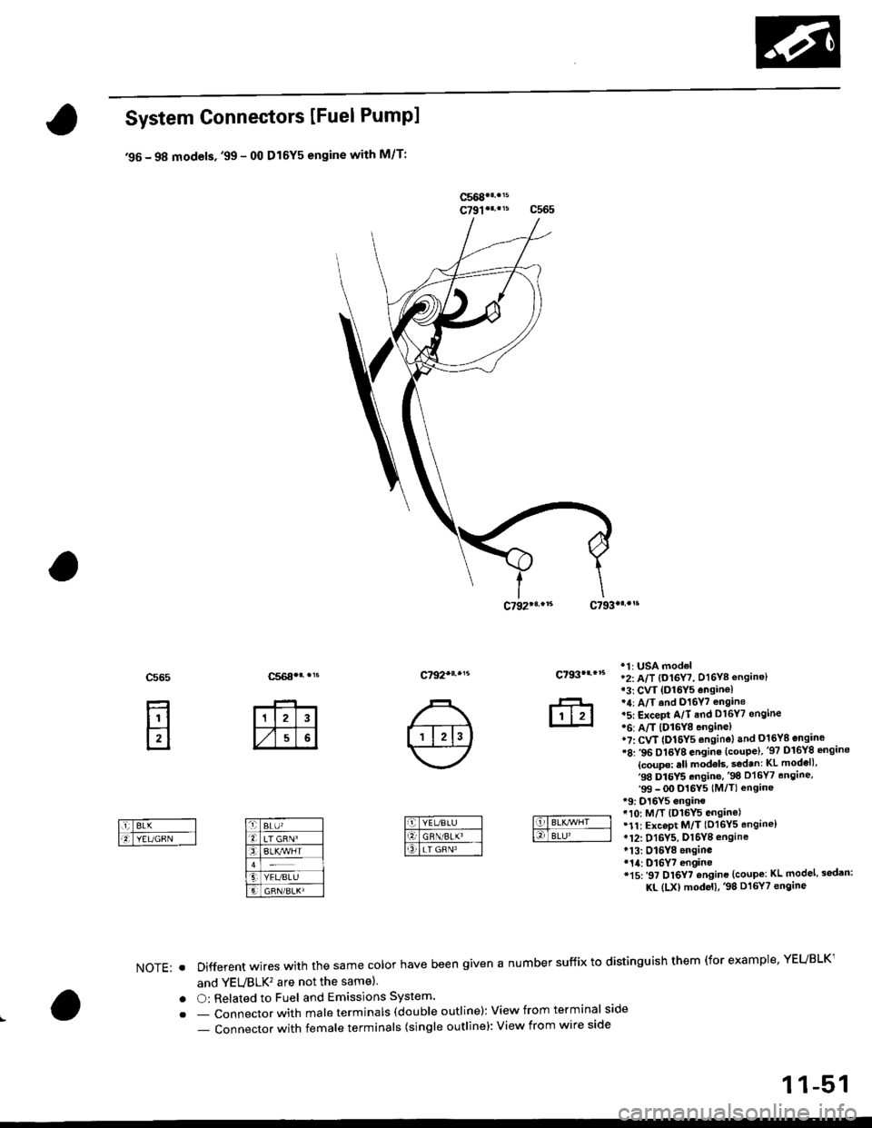
System Connectors [Fuel Pumpl
'95 - 98 models, '99 - 00 Dl6Y5 engine with M/T:
ffi
c565
E
c792*r,.'5c793|.,.s
*1r USA mod€l'2: A/T {O16Y7, D16Y8 ensine}13: CVT {O16Y5 ensin€l*4: A/T ind D16Y7 .ngane*5: ExceFt A/T end D16Y7 engine'6: A/T lDl6Y8 enginel*7: CvT (Dl6Y5 enginoland 016Yg engine'8: ,96 Dl6YB engine {coupe),'97 Dl6Y8 sngine
{coupe: sll models, s€d.nr KL modell,'98 Dl5Y5.ngine,'98 D16Y7 engine,'99 - OO Dl6Y5 (M/Tl enginer9: D16Y5 onginet10: M/T {D15Y5 ensinelr1t: ExceDt M/T (D16Y5 engine)tl2: D16Y5, Dl6Yg engine*13: Dl6Y8 enginer14: D16Y7 engine*15:'97 Dl6Y7 ensine {coupe: KL model, sodan:
KL (LX) modeu,'98 Dt6Y7 engine
NOTE: . Different wires with the same color have been given a number suffix to distinguish them (for example' YEUBLK1
and YEVBLK'� are not the samel.
. O: Related to Fuel and Emissions System'
. - Connector with male terminals (dou ble outline): View f rom term inal side
- Connector with female terminals (single outline): View from wire side
c7931...15
ffi
1 1-51