pink HONDA CIVIC 1997 6.G Workshop Manual
[x] Cancel search | Manufacturer: HONDA, Model Year: 1997, Model line: CIVIC, Model: HONDA CIVIC 1997 6.GPages: 2189, PDF Size: 69.39 MB
Page 207 of 2189

Main Bearing
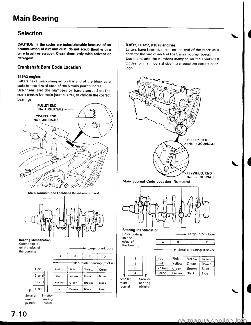
Selection
CAUTION: lf the codes are indecipherable because of anaccumulation of dirt and dust, do not scrub them with a
wire brush or scraper. Clean them only with solvent ol
deiergent.
Crankshaft Bore Code Location
81642 engine:
Letters have been stamped on the end of the block as acode for the size of each of the 5 main journal bores.
Use them, and the numbers or bars stamped on the
crank {codes for main journal size), to choose the correct
beaflngs.
Main JournalCode Locations {Nombers or Barc)
Eearing ldentificationColor code rson lhe edge ofthe bear ng.Larger crank bore
acD
-----------""' Smallerbeanngtlhrcker)
9""1B':""
Alack
Black
Alue
7-10
\
D16Y5, D16Y7, D16Y8 engines:
Letters have been stamped on the end of the block as acode for the size of each of the 5 main journal bores.
Use them, and the numbers stamped on the crankshaft(codes for main journal size), to choose the correct bear-
Ings.
Main Journal Code Location (Numbers)
\
Color codeon theedge ofthe bearing-
Ldrger crank bore
Smaller bea ng {th'cker)
lr-l
t#lt+,tlf l 4 tlf '- 't
Smaller Smallermaan bearingjournal {thicker)
RedPinkGreen
PinkGreenBrown
GreenBrownBlack
GreenBrownBlackElue
I
Bearing ldentification
BcD
Page 208 of 2189

Connecting Rod Bearings
Clearance
Remove the connecting rod cap and bearing half
Clean the crankshaft rod iournal and bearing half
with a clean shop towel.
Place plastigage across the rod journal.
Reinstall the bearing half and cap, and torque the nuts.
Torque
Bl6A2 engine:
40 N.m (4.1 kgl.m, 30 lbf'ft)
Dr6Y5, D16Y7, D16Y8 enginss:
31 N'm (3.2 kgf.m, 23 lbf ftl
NOTE| Do not rotate the crankshaft during inspection.
Remove the rod cap and bearing half and measure
the widest part of the plastigage.
Connecting Rod Bearing-to.Journal Oil Glearance:
816A2 engine:
Standard lNewl: 0.032 - 0.050 mm
10.0013 - 0.0020 in)
Service Limit: 0.06 mm 10.002 inl
D16Y5, D16Y7, D16Y8 engines:
Standard lNew): 0.020 - 0.038 mm
(0.0008 - 0.0015 in)
Service Limit 0.05 mm 10.002 inl
'1.
4.
lf the plastigage measures too wide or too narrow'
remove the upper half of the bearing, install a new,
complete bearing with the same color code (select
the color as shown in the right column), and
recheck the clearance.
CAUTION: Do not lile, shim, or scrape the bearings
or the caps to adiust clgarance.
lf the plastigage shows the clearance is still incorrect.
try the next larger or smaller bearing (the color listed
above or below that one), and check clearance again.
NOTE: lf the Droper clearance cannot be obtained
by using the appropriate larger or smaller bearings,
replace the crankshaft and start over.
PLASTIGAGE STRIP
\
7.
7-11
Selection
CAUTION: lf the codes are indecipherable because of
an accumulation of dirt and dust, do not sclub them
with a wile brush or scraper. Clean them only with sol-
vent or detergent,
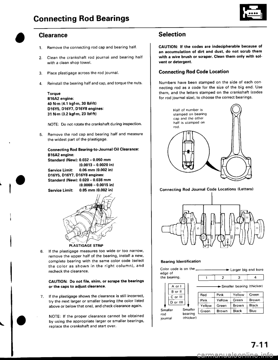
Connecting Rod Code Location
Numbers have been stamped on the side of each con
necting rod as a code for the size of the big end Use
them, and the letters stamped on the crankshaft (codes
for rod journal size), to choose the correct bearlngs
Half of number ls
stamped on bearingcap and the otherhalf is stamped onrod.
Bearing ldentilication
Color code is on theedge ofthe bearing.
lfA--;T] |
lle"'tt l;llcorlll ll
I lD;;ilril |l-l
Larger brg end bore
Smaller Smallerrod bearlngjournal (thicker)
---------------- Smallerbearing{thrcker)
RedPinkGreen
PinkGreen
GreenErownBlack
GreenBrownBlackBlue
1234
Connecting Rod Journal Code Locations (Lettels)
Page 1475 of 2189

t
Five-step Troubleshooting
2.
1.Verify The Complaint
Turn on all the components in the problem circuit to
verify the customer complaint. Note the symptoms.
Do not begin disassembly or testing until you have
narrowed down the problem area.
Analyze The Schematic
Look up the schematic for the problem circuit.
Determine how the circuit is supposed to work by
tracing the current paths from the power feed
through the circuit components to ground. lf several
circuits fail at the same time, the fuse or ground is a
likely cause.
Based on the symptoms and your understanding of
the circult operation, identify one or more possible
causes of the problem.
lsolate The Problem By Testing The Circuit
Make circuit tests to check the diagnosis you made
in step 2. Keep in mind that a logical, simple proce-
dure is the key to efficient troubleshooting. Test for
the most likely cause of failure first. Try to make
tests at points that are easily accessible.
Fix The Problem
Once the specific problem is identified, make the
repair. Be sure to use proper tools and safe proce-
dures.
Make Sure The Circuit Works
Turn on all components in the repaired circuit in all
modes to make sure you've fixed the entire prob-
lem. lf the problem was a blown fuse, be sure to
test all of the circuits on the fuse, Make sure no new
problems turn up and the original problem does not
recur.
3.
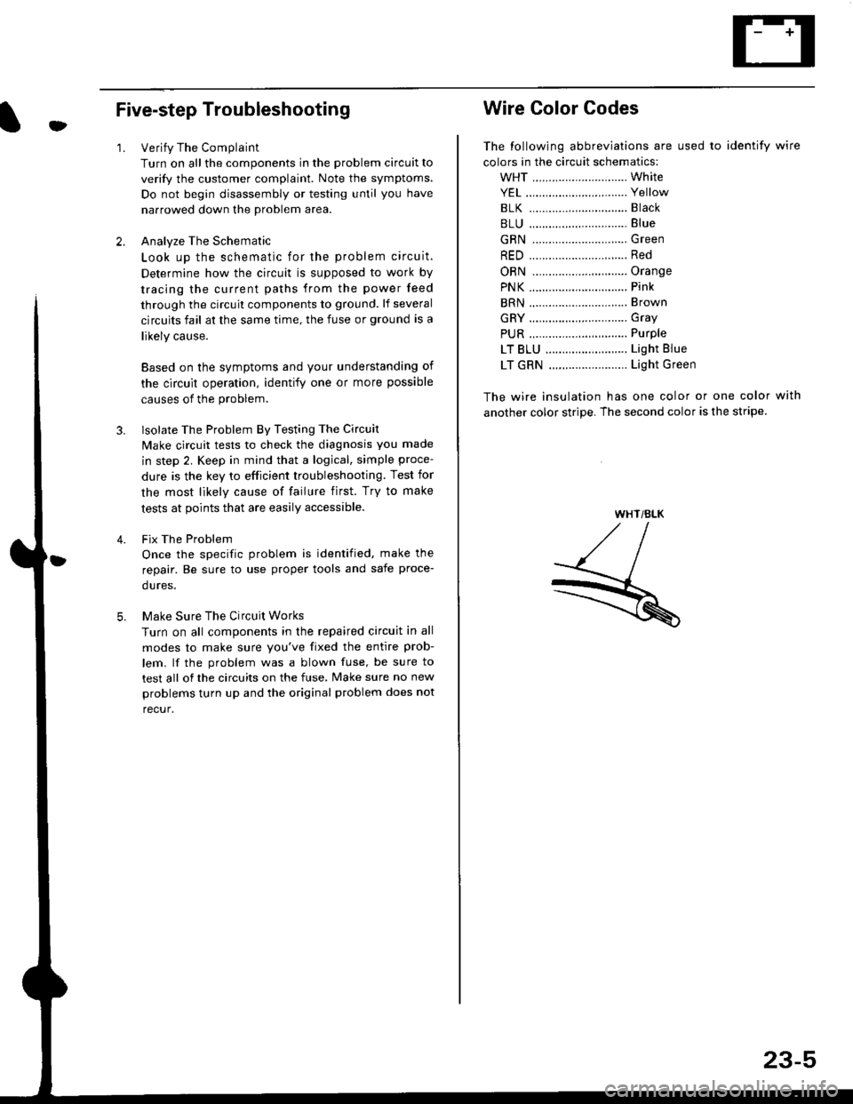
Wire Color Codes
The following abbreviations are used to identify wire
colors in the circuit schematics:
wHT ............................. White
YEL ............................... Yellow
BLK ............,.,...............81ack
BLU .............................. Blue
GRN .............................Green
RED .......................,...... Red
ORN ............................. Orange
PNK .............................. Pink
BRN .............................. Brown
GRY .............................. Gray
PUR .,.................,.,........ Purple
LT BLU ......................... Light Blue
LT GRN ........................ Light Green
The wire insulation has one color or one color with
another color stripe. The second color is the stripe.
WHT/BLK
23-5
Page 1825 of 2189

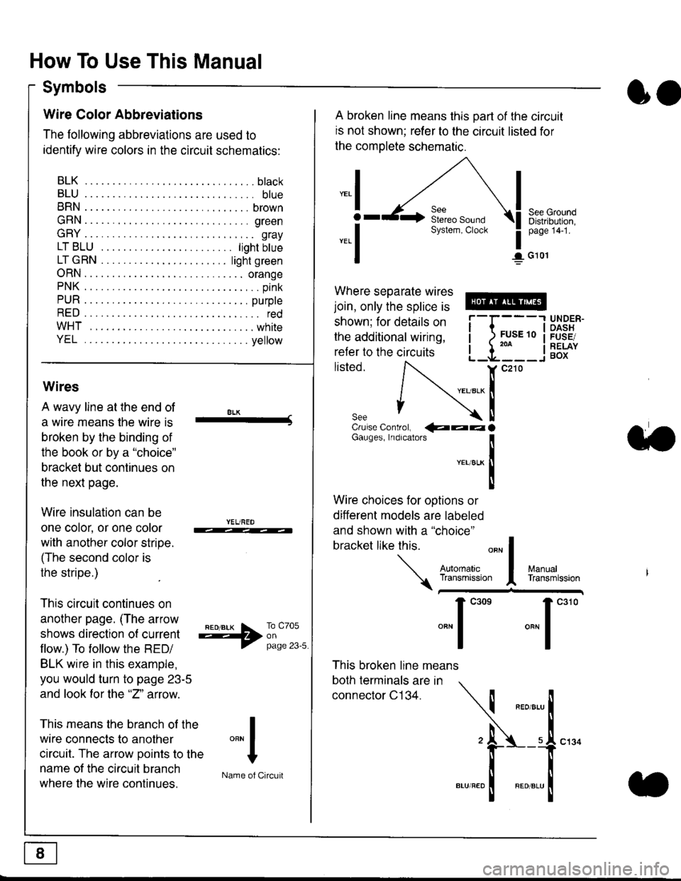
How To Use This Manual
Symbols
oo
Wire Color Abbreviations
The following abbreviations are used to
identify wire colors in the circuit schematics:
BLK.... .........b|ack
BLU.... ......... blue
BRN.... ,....... brown
GRN.... ........ green
GRY.... ......,.. gray
LTBLU . .....lightbtue
LTGRN. ....lightgreen
ORN.... ....... orange
PNK .... .......,.. pink
PUR .... ........ purple
RED .... .......... red
WHT... .........white
YEL .... ........ yellow
A broken line means this part of the circuit
is not shown; refer to the circuit listed for
the complete schematic.
"ral
o
-.1
See GroundDistribution,page 141.
I G101
Where separate wires
join, only the splice is
shown; for details on
the additional wiring,
refer to the circuits
listed.ili::i
{[
UNDER-OASHFUSE/RELAYBOX
Wires
A wavy line at the end of
a wire means lhe wire is
broken by the binding of
the book or by a "choice"
bracket but continues on
the next page.
Wire insulation can be
one color, or one color
with another color stripe.
(The second color is
the stripe.)
This circuit continues on
another page. (The arrow
shows direction o{ current
flow.) To tollow the RED/
BLK wire in this example,
you would turn to page 23-5
and look for the "2" anow.
This means the branch of the
wire connects to another
circuit. The arrow Doints to the
name of the circuit branch
where the wire continues.
8LK-Cruise Control, €�aaaGauges, Indrcalors
!YEUsLK
Ttl
Wire choices for options or
different models are labeled
and shown with a "choice"
bracket like this.
This broken line means
both terminals are in
connector C134.
a.
+##l:i""lManuallransmission
ryil;::,
.""1
""'
"""1".'0
I
""^l
:-lName of Circuit