main fi HONDA CIVIC 1998 6.G Workshop Manual
[x] Cancel search | Manufacturer: HONDA, Model Year: 1998, Model line: CIVIC, Model: HONDA CIVIC 1998 6.GPages: 2189, PDF Size: 69.39 MB
Page 686 of 2189
Description
Power Flow (cont'dl
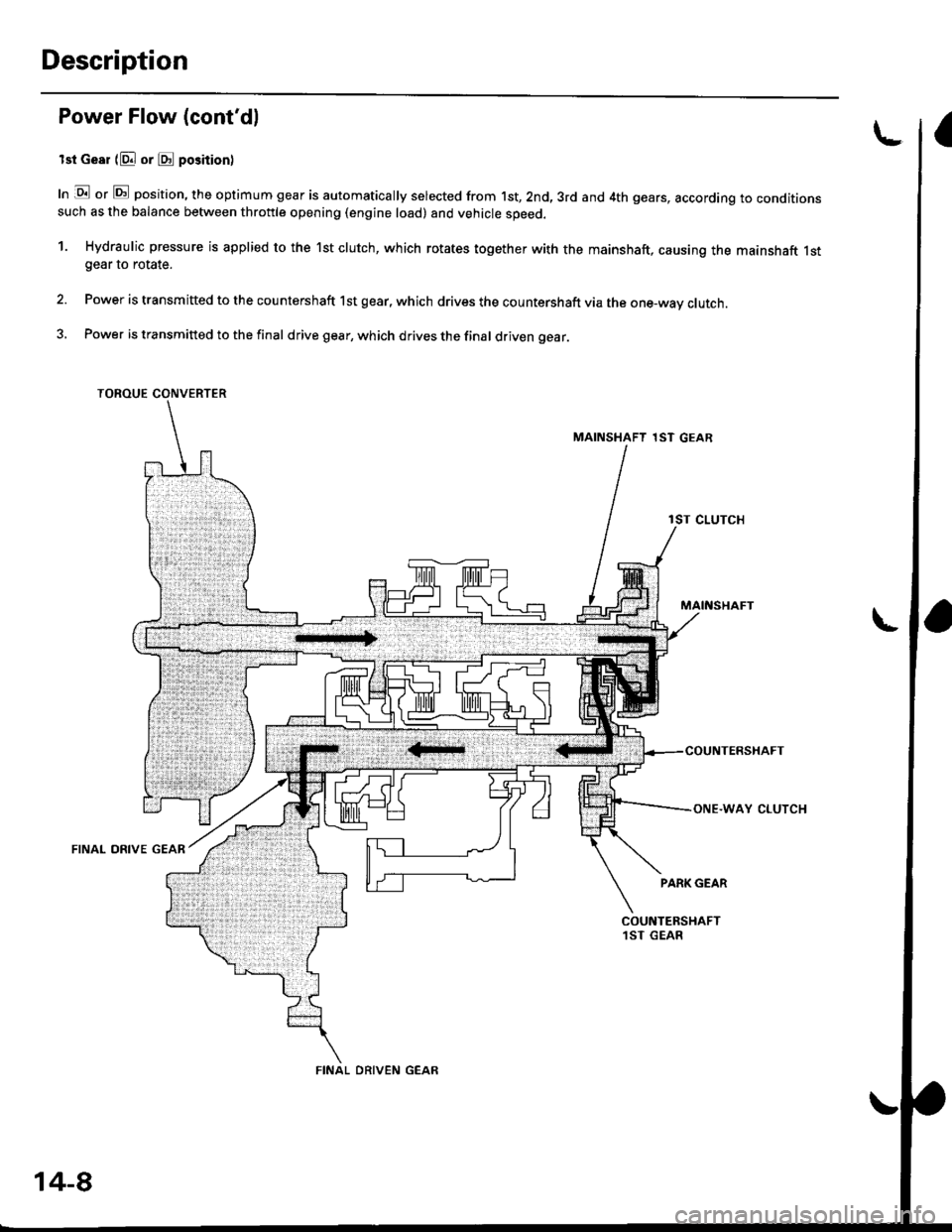
lst Gesr (E or @ position)
In lE or E position, the optimum gear is automatically selected from 1st,2nd,3rd and 4th gears, according to conditionssuch as the balance between throttle opening (engine load) and vehicle speed.
1. Hydraulic pressure is applied to the 1st clutch, which rotates together with the mainshaft, causing the mainshaft 1stgear to rotate.
Power is transmitted to the countershaft 1st gear, which drives the countershaft via the one-way clutch.
Power is transmitted to the final drive gear, which drives the final driven gear.
TOROUE CONVERTER
MAINSHAFT 1ST GEAR
lST CLUTCH
MAINSHAFT
AY CLUTCH
FINAL DRIVE GEAR
PARK GEAR
L
COUNTERSHAFT1ST GEAR
14-8
Page 687 of 2189
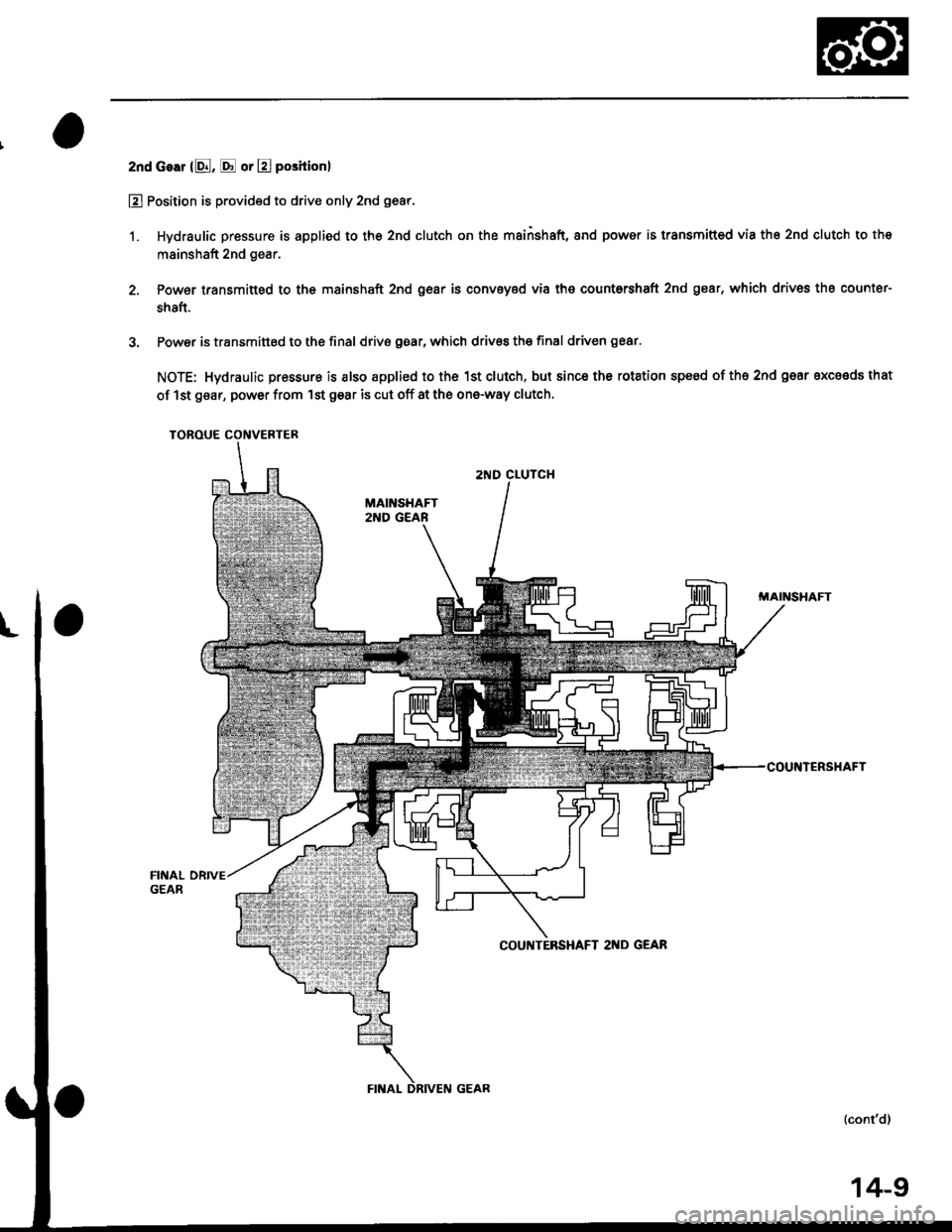
2nd Gear {8, E or E position)
E Position is provided to drive only 2nd gear.
1. Hydraulic pressure is applied to the 2nd clutch on the mainshaft, and power is transmifted via the 2nd clutch to the
mainshaft 2nd gear.
2, Powet transmitted to the mainshaft 2nd gear is conveyed via tho countorshaft 2nd gear, which drivos the counter-
shaft.
3. Power is transmined to the final drivB gear, which drives the final driven ge8r.
NOTE: Hydraulic pressure is also applied to the 1st clutch, but since the rotation speed of ths 2nd gear excaads that
of lst gear, power from 'lst gear is cut off at the one-way clutch.
TOROUE CONVERTER
2ND CLUTCH
MAII'ISHAFT
COUNTEBSHAFT 2I{D GEAR
(cont'd)
14-9
Page 688 of 2189

Description
Power Flow (cont'dl
3rd Gear (bl or bd positionl
1. Hydraulic pressure is applied to the 3rd clutch. Power from the mainshaft 3rd gear is transmitted to the countershaft3rd gear.
2. Power is transmitted to the final drive gear, which drives the tinal driven gear.
NOTE: Hydraulic pressure is also applied to the 1st clutch, but since the rotation speed of 3rd gear exceeds that of 1stgear, power from lst gear is cut off at the one-way clutch.
TOROUE CONVERTER
MAINSHAFT 3RD GEAR
MAINSHAFT
COUNTERSHAFT
3RD GEAB
3RD CLUTCH
14-10
DRIVEN GEAR
Page 689 of 2189
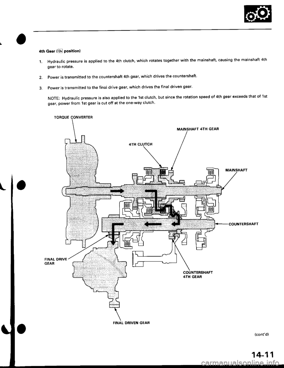
4th cear lE position)
1. Hydraulic pressure is applied to the 4th clutch, which rotates together with the mainshaft, causing the mainshaft 4th
gear to rotate.
2. Power is transmitted to the countershaft 4th gear' which drives the countershaft'
3. Power is transmitted to the final drive gear, which drives the final driven gear'
NOTE: Hvdraulic pressure is also applied to the lst clutch, but since the rotation speed of 4th gear exceeds that of 1st
gear, power from 1st gear is cut off at the one-way clutch
TOROUE
MAINSHAFT 4TH GEAR
COUNTERSHAFT
FINAL ORIVEN GEAR
14-11
Page 690 of 2189
Description
Power Flow (cont'd)
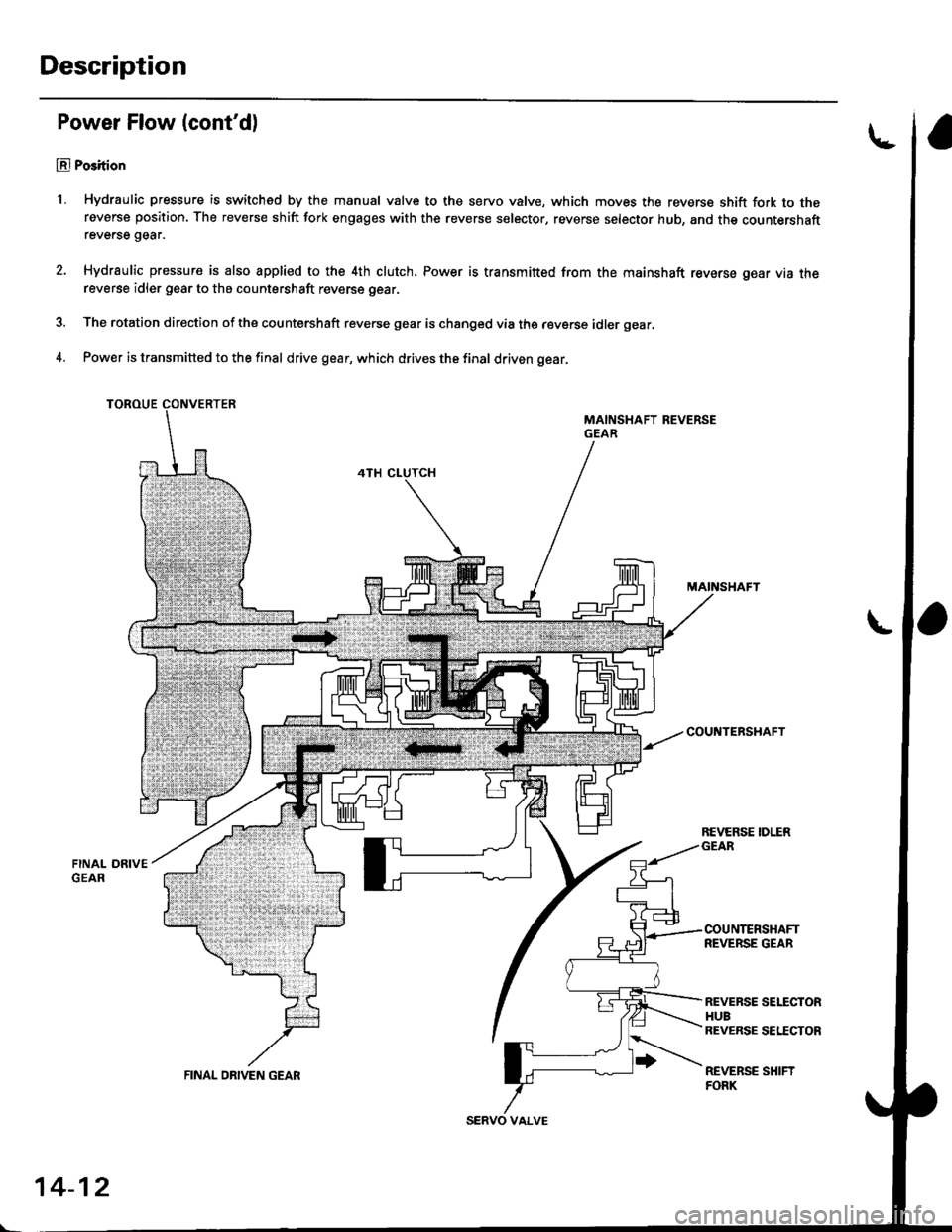
El Po3ition
1, Hydraulic pressure is switched by the manual valve to the servo valve, which moves the reverse shift fork to thereverse position. The reverse shift fork engages with the reverse selector, reverse selector hub, and the countershaftreverse gear.
Hydraulic pressure is also applied to the 4th clutch. Power is transmitt€d from the mainshaft reverse gear via thereverse idler gear to the countershaft reverse gear.
The rotation direction of the countershaft reverse gear is changed via the reverse idler gear,
Power is transmitted to the final drive gear, which drives the final driven gear.
TOROUE
MAINSHAFT
COU TERSHAFT
REVERSE SELECTORHUBREVERSE SETICTOR
REVERSE SHIFTFORK
REVERSE IDLER
14-12
FINAL ON|VEN GEAR
Page 697 of 2189
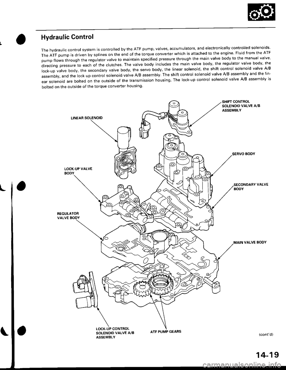
Hydraulic Control
The hydraulic control system is controlled by the ATF pump, valves, accumulators, and electronically controlled solenoids'
TheATFpUmpisdrivenbysp||nesontheendofthetorqueconverterWhichisattachedtotheengine.F|uidfromtheATF
pumpf|owsthroughtheregu|atorva|vetomajntainspecifiedpressurethroughthemainva|vebodytothemanuaIva|ve'
directingpressuretoeachofthec|utches.Theva|vebodyinc|udesthemainvaivebody,theregu|atorvalvebody,the
|ock-upva|vebody,thesecondaryVa|vebody,theservobody,theIinearso|enoid,theshiftcontro|so|enoidva|velVB
assembly, and the lock up control solenoid valve A/B assembly. The shift control solenoid valve Ay'B assembly and the lin-
ear solenoid are bolted on the outside of the transmission housing. The lock-up control solenoid valve A,/B assembly is
bolted on the outside of the torque converter housing
SHIFT CONTROLSOLENOIO VALVE A/8
ASSEMBLY
LINEAR SOLENOID
SERVO BOOY
REGULATORVALVE BODY
VALVE
VALVE BOOY
(cont'd)
CONTROLSOLENOID VALVE A/BASSEMBLY
ATF PUMP GEARS
14-19
Page 698 of 2189

Description
Hydraulic Control (cont'dl
Msin Valve Body
The main valve body houses the manual valve, the 1-2 shift valve, the 2nd orifice control valve, the cpB valve, the modu-lator valve' the servo control valve, and the relief valve. The primary functions of the main valve body are to swatch fluidpressure on and off and to control the hydraulic pressure going to the hydraulic control svstem.
2ND ORIFICE CONTROTVALVE
1-2 SHIFT VALVE
RELIEF VALVE
CPC VAL
3-4 SHTFT V
VALVE
Socondary Valve Body
The secondary valve body is located on the main valve body. The secondary valve body houses the 2-3 shift vatve, the 3-4shift valve, the 3-4 orifice control valve, the 4th exhaust valve, and the CpC valve.
CONTROL
2.3 SHIFT VALVE
4TH EXHAUST VALV€
VALVE
14-20
VALVE
Page 699 of 2189
\
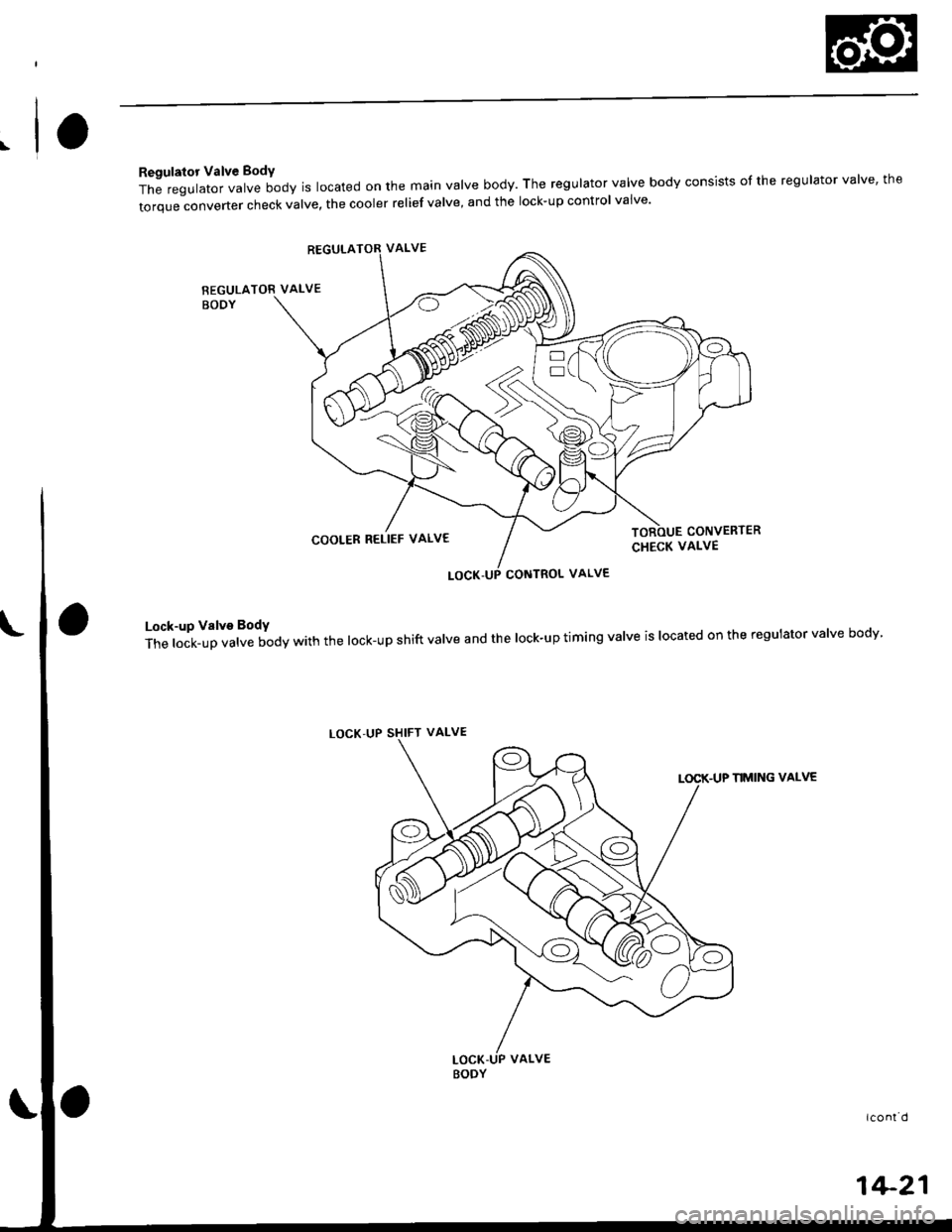
Regulator Valve BodY
The regulator valve body is located on the main valve body. The regulator valve body consists of the regulator valve' the
torque-converter check valve, the cooler relief valve, and the lock-up control vaive'
REGULATOR VALVE
BODY
REGULATOR VALVE
COOLER RELIEF VALV€
LOCK,UP SHIFT VALVE
CONVERIER
CHECK VALVE
CONTROL VALVE
Lock-up Valve BodY
The lock-up valve body with the lock-up shift valve and the lock-up timing valve is located on the regulator valve bodv
LOCK-UP NMING VALVE
icont d
1+21
Page 700 of 2189
Description
Hydraulic Control (cont'dl
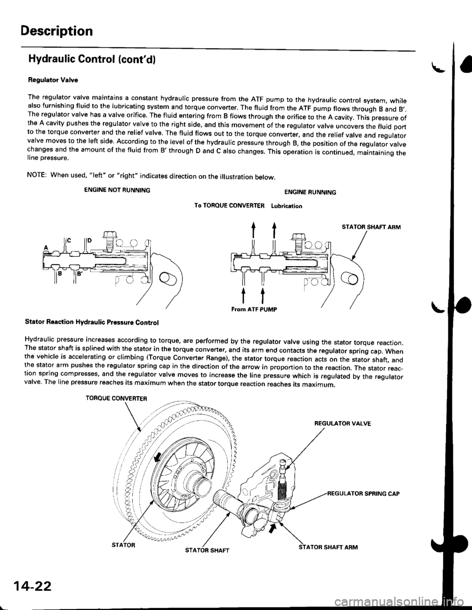
Regulator Valve
The regulator valve maintains a constant hydraulic pressure from the ATF pump to the hydraulic control system, whitealso furnishing fluid to the lubricating system and torque converter. The fluid from the ATF pump flows through B and 8,.The regulator valve has a valve orifice. The fluid entering from B flows through the orifice to the A cavity. This pressure ofthe A cavity pushes the regulator valve to the right side, and this movement of the regulator valve uncovers the fluid portto the torque converter and the relief valve. The fluid flows out to the torque converter, and the relief valve and regulatorvalve moves to the left side. According to the level of the hydraulic pressure through B, the position of the regutator vatvechanges and the amount of the fluid from B' through D and c also changes. This operation is continued. maantaining theline pressure,
NOTE: When used. "|eft" or "right" indicates direction on the illustration betow.
ENGINE NOT RUNNING
TOROUE CONVERTER
ENGINE RUNNING
To TOROUE CONVERTER Lubrication
Stator Roaction Hydraulic Prossur6 Control
Hydraulic pressure increases according to torque, are performed by the regulator valve using the stator torque reaction.The stator shaft is splined with the stator in the torque converter, and its arm end contacts the regulator sprang cap. whenthe vehicle is accelerating or climbing (Torque Convert€r Range), the stator torque reaction acts on the stator shaft, andthe stator arm pushes the regulator spring cap in the direction of the arrow in proponion to the reaction. Jne stator reac-tion spring compresses, and th€ reoulator valve moves to increase the line pressure which is regulated by the regulatorvalve. The line pressure reaches its maximum when the stator torque reaction reaches its maximum.
STATOR SHAFT ARM
REGULATOR VALVE
14-22
STATORATOR SHAFT ARM
SPRING CAP
Page 707 of 2189
I
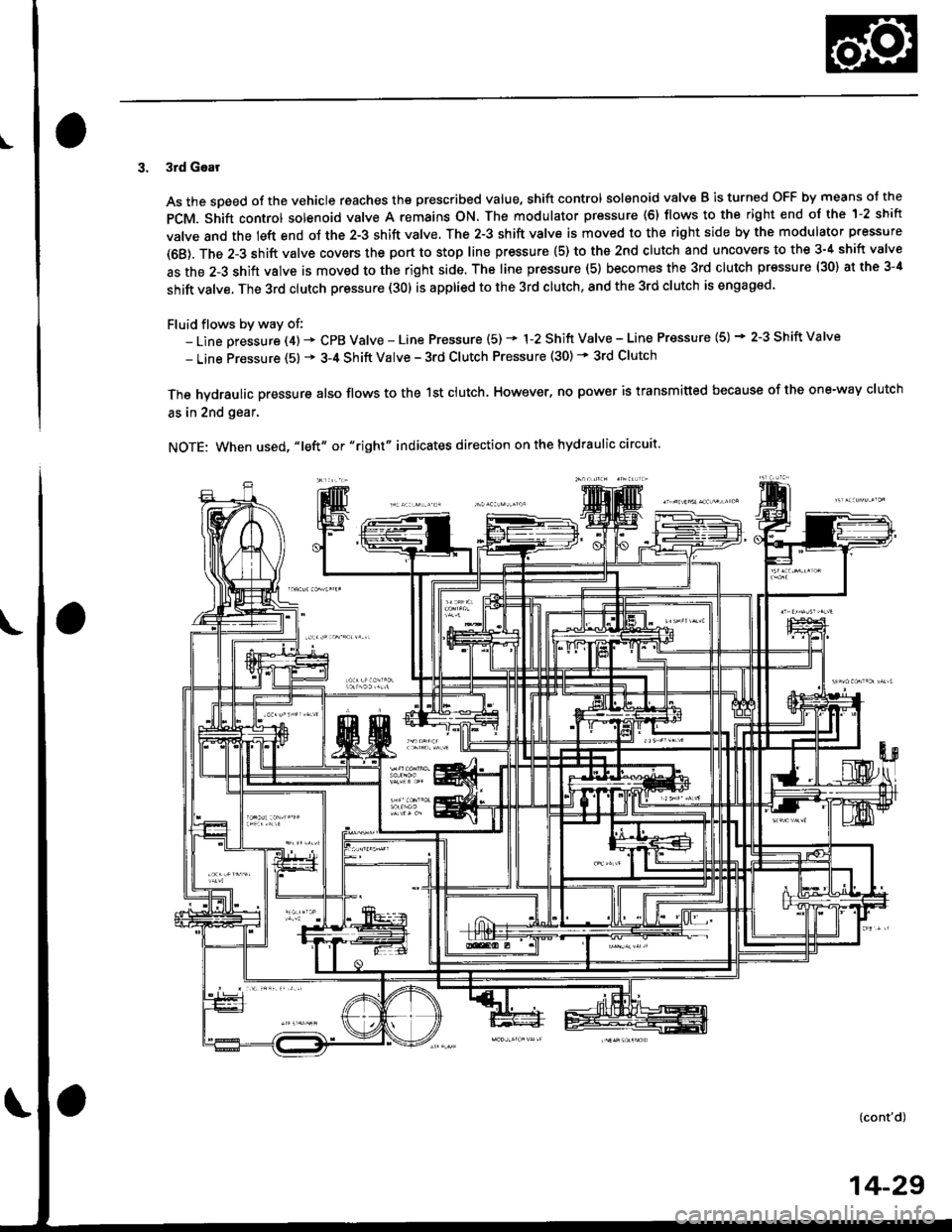
3. 3rd Gear
As the soeed of the vehicle reaches the prescribed value, shift control solenoid valve B is turned OFF by means ol the
pCM. Shift control solenoid valve A remains ON. The modulator pressure (6) flows to the right end of the 1-2 shift
valve and the left end oJ the 2-3 shift valve. The 2-3 shift valve is moved to the right side by the modulator pressure
(68). The 2-3 shift valve covers the port to stop line pressure (5) to the 2nd clutch and uncovers to the 3-4 shift valve
as the 2-3 shift valve is moved to the right side. The line pressure (5) becomes the 3rd clutch pressure (30) at the 3-4
shift valve. The 3rd clutch pressure (30) is applied to the 3rd clutch, and the 3rd clutch is engaged'
Fluid flows by way of:- Line Dressure (4) * CPB Valve - Line Pressure (5) * 1-2 Shift Valve - Line Pressure (5) * 2-3 Shift Valve
- Line Pressure (5) * 3-4 Shift Valve - 3rd Clutch Pressure (30) - 3rd Clutch
The hvdraulic pressure also flows to the 1st clutch. However, no power is transmitted because of the one-way clutch
as in 2nd gear.
NOTE: When used, "|eft" or "right" indicates direction on the hydraulic circuit.
14-29