d16y7 HONDA CIVIC 1998 6.G Workshop Manual
[x] Cancel search | Manufacturer: HONDA, Model Year: 1998, Model line: CIVIC, Model: HONDA CIVIC 1998 6.GPages: 2189, PDF Size: 69.39 MB
Page 856 of 2189
![HONDA CIVIC 1998 6.G Workshop Manual Transmission
_\,]ffil
Reassembly (contd)
TRANSMISSIONHANGER
MAINSHAFTSUB.ASSEMBLY
*
Ufln
$*U ./
TRANSMISSION HOUSINGMOUNTING BOLTS10 x 1.25 mm4{ N.m {4.5 kg{.m,33 lbI.ft)
TRANSMISSION HOUSING
REVER HONDA CIVIC 1998 6.G Workshop Manual Transmission
_\,]ffil
Reassembly (contd)
TRANSMISSIONHANGER
MAINSHAFTSUB.ASSEMBLY
*
Ufln
$*U ./
TRANSMISSION HOUSINGMOUNTING BOLTS10 x 1.25 mm4{ N.m {4.5 kg{.m,33 lbI.ft)
TRANSMISSION HOUSING
REVER](/img/13/6068/w960_6068-855.png)
Transmission
_\,]ffil
Reassembly (cont'd)
TRANSMISSIONHANGER
MAINSHAFTSUB.ASSEMBLY
*''
Ufln
$*U ./
TRANSMISSION HOUSINGMOUNTING BOLTS10 x 1.25 mm4{ N.m {4.5 kg{.m,33 lbI.ft)
TRANSMISSION HOUSING
REVERSE GEARCOLLAR
REVERSE GEAR
LOCK WASHER
SHIFT FORK
MAINSHAFT SPEEDSENSOR WASHER(D16Y7 engine)
MAINSHAFT
COUNTERSHAFTSUB.ASSEMBLY
OIFFER€NTIALASSEMBLY
SPEED
TRANSMISSIONHOUSING GASKET
TOROUE CONVERTERHOUSING
14-178
Page 864 of 2189
Transmission
Installation {cont'd)
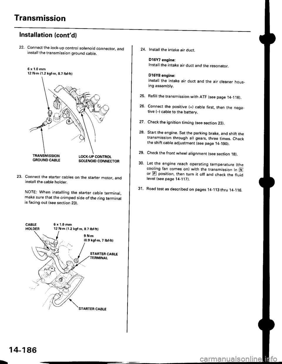
Connect the lock-up control solenoid connector. andinstall the transmission ground cable.
6 x '1.0 mm12 N.m {1.2 kgf.m, 8.7 lbl.ft}
LOCK.UP CONTROLSOLENOID CONNECTOR
Connect the staner cables on the staner motor. andinstall the cable holder.
NOTE; When installing the starter cable terminal.make sure that the crimped side of the ring terminalis facing out (see section 23).
6x1.0mm12 N.m 11.2 kg{.m.8.7 tbtftl
{0.9 kg'f.m, 7 lbf.ftl
TRANSMISSIONGROUND CABLE
b
14-186
STARTER CAELE
24. Installthe intake air duct.
D16Y7 engine:
Install the intake air duct and the resonaror.
D16Y8 engine:
lnstall the intake air duct and the air cleaner hous_ang assembly.
25. Refill the transmission with ATF (see page 14_1.18).
26. Connect the positive (+) cable first. then the nega-tive (-) cable to the battery.
27. Check the ignition timing (see section 23).
28. Start the engine. Set the parking brake, and shift thetransmission through all gears. three times. Checkthe shift cable adjustment (see page 14_190).
29, Check the front wheel alignment (see section 1g).
30. Let the engine reach operating temperature (thecooling fan comes on) with the transmission in Nor @ position, then turn it off and check the fluidlevel (see page 14- 7).
31. Road test as described on pages 14-113 thru ,14_116.
Page 1490 of 2189
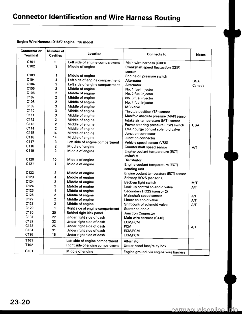
Gonnector ldentification and Wire Harness Routing
Engine Wire Harness {D16Y7 engine}: '96 model
Conneclor or
Terminal
Number ot
CavhiesLocationConnects toNotes
c101
c102
c 103
c104
c104
c105
c'r06
c107
c 108
c 109
c110
c111
c112
c l13
c't14
LttS
cl16
cl17
c118
cl19
c120
c121
c123
c124
c124
c125
c126
c't27
c12a
c129
c130
c131
c132
c133
c134
c135
10
1
4
5
'14
14
10
1
,,
2
2
1
22
31
16
No. 1 fuel injector INo. 2 fuel injector
No. 3 fuel injector INo,4 fuel injector
IAC valve l
Throttle position (TP)sensor IManifold absolute pressure (MAP) sensorIntake ai. temperature (lAT) sensor ]Power steering pressure (PSP) switch I USAEVAP purge control solenoid valve IJunction connector
Junction connector IVehicle speed sensor (VSS) |Countershaft speed sensor AlTEngine coolant temperature (ECT) I
Main wire harness (C303)
Crankshaft speed fluctuation (CKF)
sensor
Engine oil pressure switch
Alternator
Alternator
switch A
Distributor
Engine coolant temperature (ECT)
sending unit
Engine coolant temperature lECT) sensor
Primary H02S (sensor 1)
Back-up light switch
Lock-up control solenoid valve
Secondary HO2S (sensor 2)
Mainshaft speed sensor
Linear solenoid valve
Shift control solenoid valve
Staner solenoid
Junction Connector
Main wire harness {C446)ECM/PCM
PCM
ECM/PCM
ECM/PCM
Left side of engine compartment
Middle of engine
Middle of engine
Left side of engine compartment
Left side of engine compartment
Middle of engine
Middle of engine
Middle of engine
Middle of engine
Middle of engine
Middle of engine
Middle of engine
Middle of engine
Middle of engine
Middle of engine
Middle of engine
Middle of engine
Left side of engine compartment
Middle of engine
Middle of engine
Middle of engine
Middle of engine
Middle of engine
Middle of engine
Middle of engine
Middle of engine
Middle of engine
Middle of engine
Middle of engine
Middle of engine
Right side of engine compartment
Behind right kick panel
Under right side of dash
Under right side of dash
Under right side of dash
Under right side of dash
Under right side of dash
USA
Canada
M/T
AtJ
Afi
T101
T102
Left side of engine compartment
Right side of engine compartment
Alternator
Under-hood fuse/relay box
G101Middle of engineEngine ground, via engine wire harness
23-20
Page 1545 of 2189
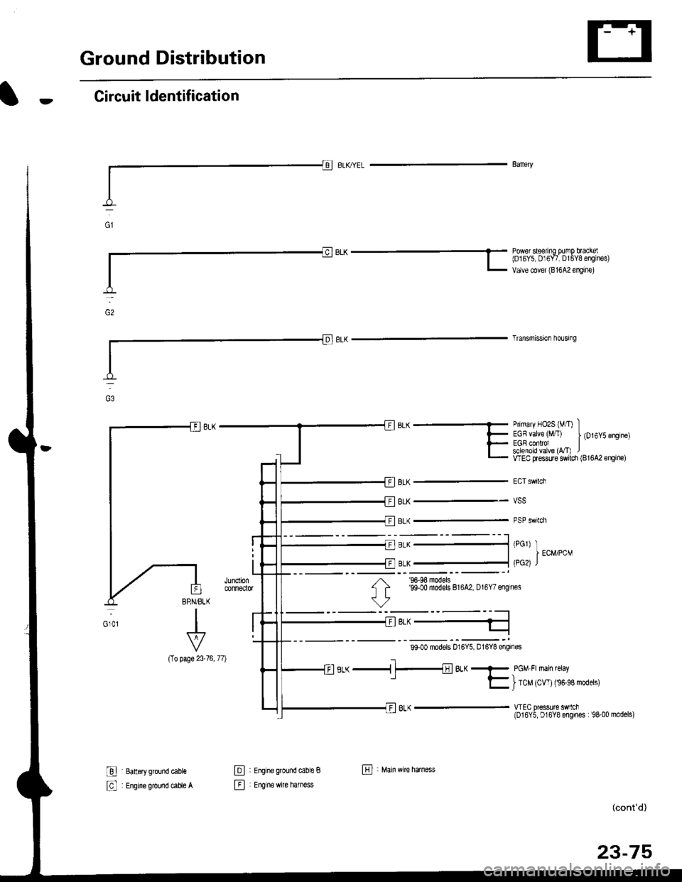
Ground Distribution
Circuit ldentification
(To
I 8an6ry ground cable
: Engine ground caue A
Primary HO2S (M/I) IEGR valve (,tffT) | {Ot6y5 engtne)EGB conrol Isllenoid va ve (vT) lwEc flessure switdr (Bl6A2engine)
vss
PSP swtch
Baaery
BLK -* bqiu"trl'ff lso",ilE o;l?f ;".,L ur,u" "ou.,,r,oo, "*'n",
Trlnsmission ho!gng
BLK
BLK
BLK
BRN/BLK
I
I
Vp?oe 23-76, 77)
'96-98 models'99-00 models 816A2, D16Y7 engines
99-00 modors D16Y5, D16Y8 engines
s,-( -i-t;lBL(- pcM Frman reray' E ) tc" 't*' tn''n''*t'''
wEC pressurc sMch(016Y5, D16Y8 engines : 98-00 models)
@
E
Efal
i Engine grcund cable B
: Engrne wire hamess
(cont'd)
23-75
El , M"in ttire hatn"."
Page 1546 of 2189
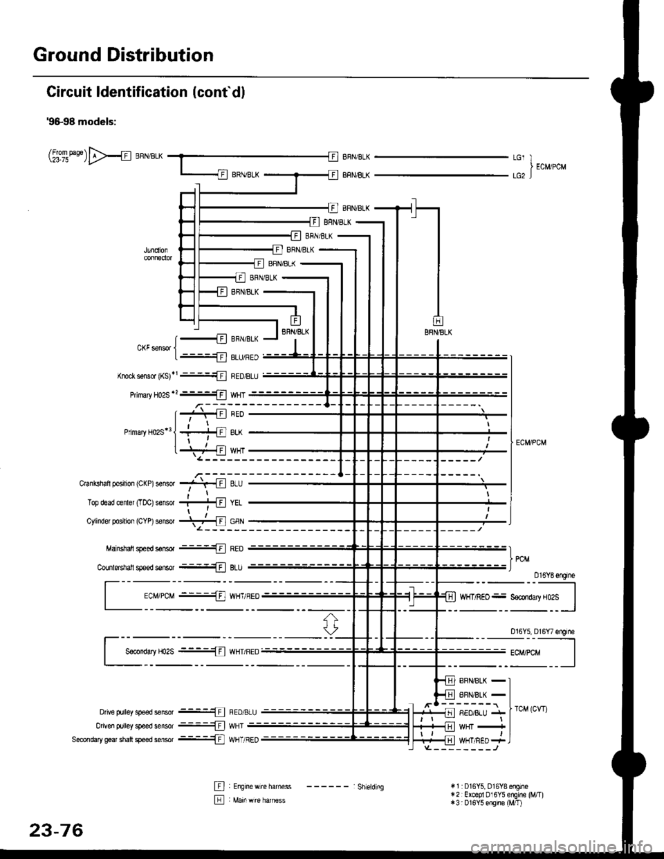
Ground Distribution
Circuit ldentification (conf dl
'9&98 models:
(t[oileas6)>{ BRN/BLKLGl II EcM/PcMlcz J
[..........{ BFNaLKCKF sensor jL .-!l 8LU/FED
Knoct s€rlsor (KS)r' ::{ REDtsLU
PimaryH02S*?- wHT
Matnsnafi g]€eo sdnsoa -'1 t I HEL)
Counlersiall speed sensor --={Fl BIU
Ecr#PcM ----Tal WHT/BED
Dive trjiley speed seftsor -1ll FED,ALU
0 ven pulley speed sensor .-lJ WHT
Seconftry gear shalt speed sansor .-!.1 WHT/RED
44:lil
ECIVPCM
)*"Dl6YBengine
Dl6Y5, D16Y7 sngine
vtl
8BM/BLK - IBBi1/BLK _ I^l^1ll'. I rcu rcwr
**' -i IWHT/RED + ]
El , Engln" *lr" h"rn""" - - - - - - : Shietorns
E : Main *re harness
23-76
* 1 :D16Y5,016Y8 engino* 2 : Excepl Dl 6Y5 engine (i//T)+3: D16Y5 engine (Mfi)
Page 1547 of 2189
![HONDA CIVIC 1998 6.G Workshop Manual rt
99-00 models:
(5i%ease)E>4 BRNiBLK
i.,.,].,,-
ERNi BtK
BRIVBLK
BFN/BLK
BRN/BLK
BRN]BLK
BRIl/8LK
BFN/BLK
r * s r;l ao^r,qt r
CKF s€nsor 1t -1ll ELU/FEU
Knoq( sonsor (r15J -l !l r{EUl6LU
P maryH HONDA CIVIC 1998 6.G Workshop Manual rt
99-00 models:
(5i%ease)E>4 BRNiBLK
i.,.,].,,-
ERNi BtK
BRIVBLK
BFN/BLK
BRN/BLK
BRN]BLK
BRIl/8LK
BFN/BLK
r * s r;l ao^r,qt r
CKF s€nsor 1t -1ll ELU/FEU
Knoq( sonsor (r15J -l !l r{EUl6LU
P maryH](/img/13/6068/w960_6068-1546.png)
rt
'99-00 models:
(5i%ease)E>4 BRNiBLK
i.,.,].',,-
ERNi BtK
BRIVBLK
BFN/BLK
BRN/BLK
BRN]BLK
BRIl/8LK
BFN/BLK
r * s r;l ao^r,qt r
CKF s€nsor 1t -1ll ELU/FEU
Knoq( sonsor (r15J '-l !l r{EUl6LU
P maryHo2s*?H wHT
Mainshafl speeo ssnsor -1ll fiEU
Coutershall sp€ed sensor -+F ] BLU) ..",r.u,.0n
016Y7, Dl6Y5 (CW) ongines
;;=-"r,i,-l
Ly"::::::::
I Secondary Ho2s :{ WHT/RED-;'4:v-..1
RED/BLU - I
wHT - f rau,rru (an )
pgTpse- J
*1i016Y5, Dl6Y8engines *4:016Y7, Bl6AzerEines lcont'd)*2: Excepl DI6YSengino ([VT) *5: D16Y5, D16Y7, D16Y8Bngines* 3:Dl6Y5 sngine ([VT) *6:B16M, D16Y8,016Y5 (CW)engines
015Y5 (LVT) sngine
41-.1
Dfiv6 prirEy speeo sonsot -1l l hEL,bLU
Driven gr ley sp€ed sensor -- F I WHT
Secondary gea sian sp€ed sensor .-ll WHT/RED
E : Engine w re harness E : Rear h€al6d orygen sensor sLlb harness
IIJ : Main wire harnsss ------ shielding
816A2, Dl6Ygengiftes
23-77
Page 1575 of 2189
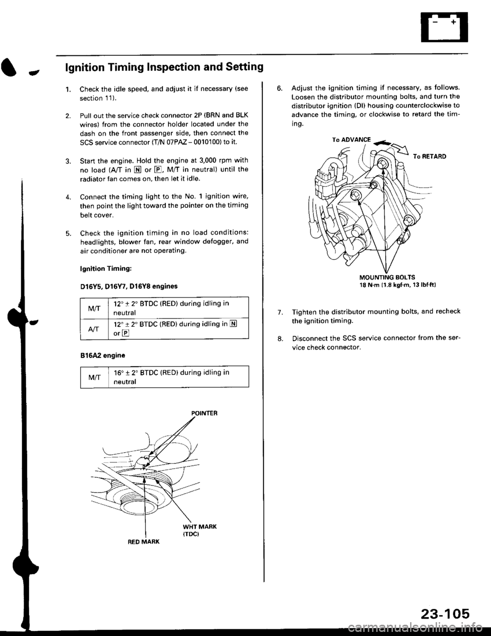
-lgnition Timing Inspection and Setting
1.Check the idle speed, and adjust it it necessary (see
section 'l '1 ).
Pull out the service check connector 2P (BRN and BLK
wires) from the connector holder located under the
dash on the front passenger side, then connect the
SCS service connector (T/N 07PAZ - 0010'100) to it.
Start the engine. Hold the engine at 3.000 rpm with
no load {A,/T in E or E. M/T in neutral) until the
radiator fan comes on, then let it idle.
Connect the timing light to the No. 1 ignition wire,
then point the light toward the pointer on the timing
belt cover.
Check the ignition timing in no load conditions:
headlights. blower fan, rear window defogger, and
air conditioner are not operating.
lgnhion Timing:
D15Y5. D16Y7, Dl6Yg engines
816A2 engine
MIT16" 12' BTDC (RED) during idling in
neutral
M/T12't 2" BTDC (RED) during idling in
neutral
l2'r 2" BTDC {RED) during idling in S
orE
POINTEB
RED MARK
23-105
ro ADVANCE -<;,
6. Adjust the ignition timing if necessary, as follows.
Loosen the distributor mounting bolts. and turn the
distributor ignition (Dl) housing counterclockwise to
advance the timing, or clockwise to retard the tim-
ing.
MOUNTING BOLTS18 N'm (1.8 kgfm, 13lblftl
Tighten the distributor mounting bolts, and recheck
the ignition timing.
Disconnect the SCS service connector from the ser-
vice check connector.
7.
Page 1581 of 2189
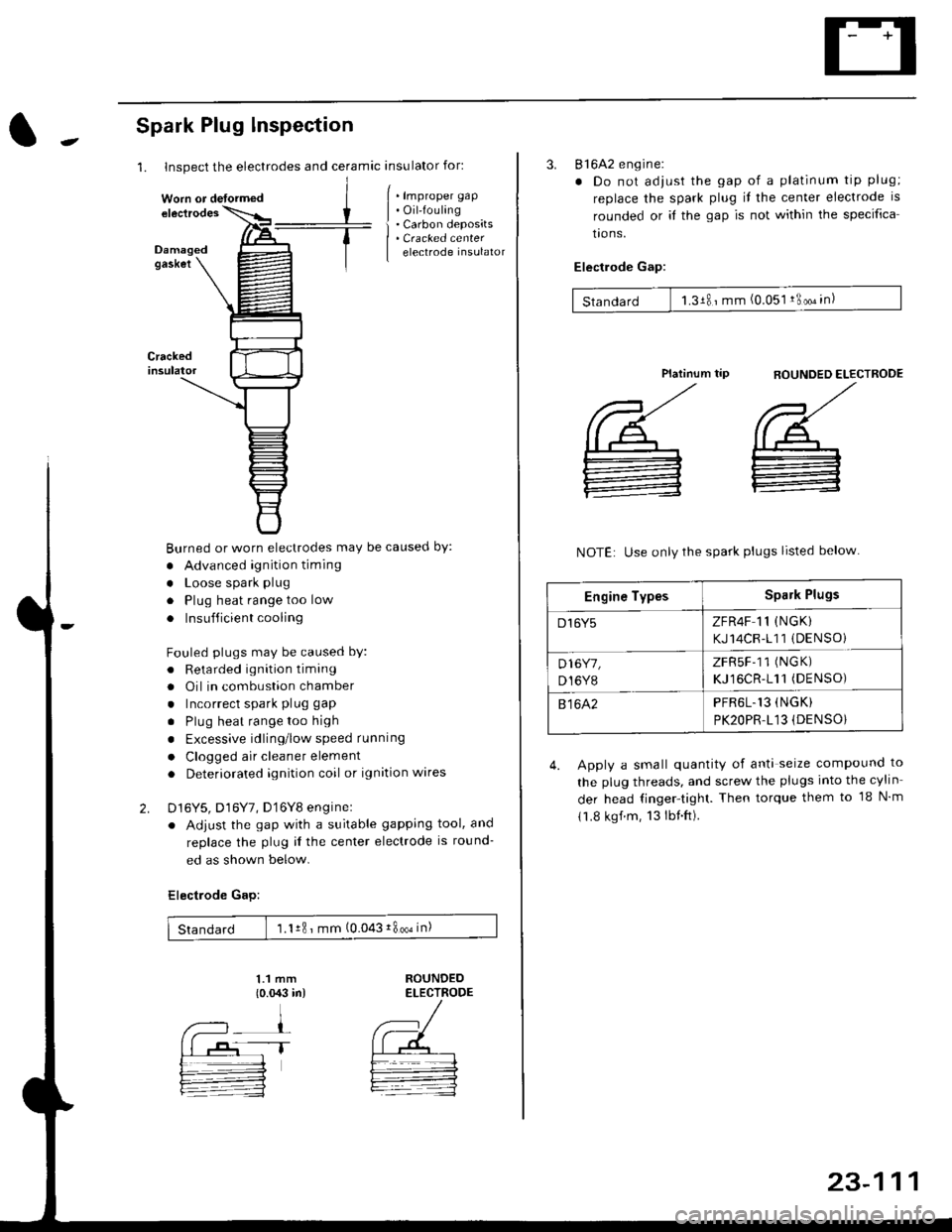
1. Inspect the electrodes and ceramic insulator for:
Spark Plug lnspection
Crackedinsulator
2.
[ . t.p,op", grp
| . Oil-fouling
i . Carbon deposits
| . Cracked center
I electrode insulator
Burned or worn electrodes may be causecl by:
. Advanced ignition timing
. Loose spark plug
. Plug heat range too low
. Insufficient cooling
Fouled plugs may be caused bY:
. Retarded ignition timang
. Oil in combustion chamber
. Incorrect spark plug gap
. Plug heat rangetoo high
. Excessive idling/low speed running
. Clogged air cleaner element
. Deteriorated ignition coil or ignition wares
D16Y5, D16Y7, D'16Y8 enginel
. Adjust the gap with a suitable gapping tool, and
replace the plug il the center electrode is round-
ed as shown below.
Electrode Gap:
1.1 mm
{o.{X:l in)ROUNDEDELECTRODE
Standard 1.1r8 ' mm (0.043i800oin)
Worn or detormed
1T
23-111
3. 816A2 engine:
. Do not adjust the gap of a platinum tip plug;
replace the spark plug il the center electrode is
rounded or it the gap is not within the specifica
tro ns.
Electlode Gap:
Standard 1.3181mm (0.051 !3oo" in)
flOUNDED ELECTROOE
',/
@_
:
Platinum tip
NOTE: Use only the spark plugs listed below
4. Apply a small quantity of anti seize compound to
the plug threads, and screw the plugs into the cylin
der head finger-tight. Then torque them to 18 N m
11.8 kgf.m, 13lbnft).
Engine TypesSpark Plugs
D16Y5ZFR4F 11 (NGK)
KJ14CR-111 (DENSOi
D16Y7,
D,I6Y8
ZFRSF-11 (NGK)
KJ16CR-111(DENSO)
81642PFR6L.13 (NGK)
PK2OPR.L13 (DENSO}
Page 1840 of 2189

Ground-to-Components I ndex
f.,lONOTE: All ground wires are BLK unless otherwise noted.
GroundPageComponents or Circuit Grounded
Battery (BLKYEL)
Steering pump bracket
t+-rg ITransmission housing
l
G101
(-1)
G101
(-2)
14-2
and
14-3
ano
14-1
Powertrain or engine control module (PG1 and pG2 are BLK: LG1 and LG2 are
BRN/BLK), EGR control solenoid valve (CW, EGR valve and lift sensor (Dt6yS enginewith M,/T), Engine coolant temperature switch, pGM-Fl main relay, power steeringpressure switch (USA), Primary HO2S (D16Y5 engine with l\/,/T), Vehicle speed sensor,VTEC pressure switch (D16Y5/D16Y8 engines), CKF sensor (BRN/BLK), Transmission
control module (CYf) (Pc1 is BLK: LG1 is BRN/BLK)
Shielding betvveen the PCM or ECM and these components (all have BRN/BLK wires):
CKF sensor, TDC/CKP/CYP sensor. Primary and secondary heated oxygen sensors.
Knock sensor (CWDl6YB engine), Mainshaft speed sensor (AiT except CVT),
I Countershaft speed sensor (A/T except CVf)
Shielding between the TCM and these components (CVT) (all have BRN/BLK wires):
Drive pulley speed sensor, Driven pulley speed sensor, Secondary gear shaft
speed sensor
Powertrain or engine control module (PG1 and pG2 are BLK; LG1 and LGz are
BRN/BLK), EGR control solenoid valve (D16Y5 engine), EGR valve (Dt685), Engine
coolant temperature switch, Fuel pressure regulator shut-off solenoid valve (D1685),
PGM-FI main relay, Power steering pressure switch (USA), Vehicle speed sensor, VTECpressure switch (All except D16Y7 engine), CKF sensor (A
except 81642) (BRN/BLK)
Shielding between the PCM or ECM and these components (all have BRN/BLK wires):
CKF sensor, TDC/CKP/CYP sensor, Primary and secondary heated oxygen sensors,
Knock sensor (All except D16Y7 engine), i/ainshaft speed sensor (Arf except CW),
Countershaft speed sensor (A,/T except CVf), Drive pulley speed sensor (CW), Drivenpulley speed sensor (CVT), Secondary gear shaft speed sensor (CVf)
I Badiator fan motor, Right front parking/turn signat tight, Right headtight
G20214-4I Cruise control actuator, Left front parking/turn signal lights, Left headlight, Rear window
I washer motor, Windshield washer motor, Washer fluid level switch (,99-'00 Canada)
G401| +-o
and
14-7
Accessory power socket, Brake fluid level switch, Clutch interlock switch (M/T), Clutchswitch (lillT with cruise/D16Y5 engine with MfD, Combination wiper switch (Z wires),
Cruise control main switch, Cruise control unit, Dash lights brightness controller, Data
link connector, Daytime running lights control unit (Canada), Gauge assembly, Horn('96-'97 models), Integrated control unit, Interlock control unit (ArI), Keyless door lock
control unit ('99-'00 models with keyless), Moonroof close and open relays, Moonroof
switch, Park pin switch (A/r), Power window relay, Rear window defogger relay, Rear
window defogger switch ('96-'98 models), Steering lock, Stereo radio tuner (,96-,98
USA: LX, EX, and HX), Turn signal/hazard relay, Windshield wiper motor.....plus
everything grounded through G402
6-6
Page 1843 of 2189
I
t
I
UNDER-HOODFUSE/RELAY BOXFUSE 52HO3 ,9IO? LTt3a
FUSE 53SATAAD10A
T102PHOTO 9l--
S€e PowerDistrib$ion,page 10-13.
WHT/REDT101PI1oIO 25
I
IJ
I
I
FUSEofiro{{oa
ALTEBNATORPage 22
nI
I
t
--1 UNDER.
sFUSE 55IIEATER MOTONatla
r^-::r BLowER| t,omacl I MoToR
i lF5:ftL--J or 50-1Ptaofo9
FUSE 55(co{DEtsER fAx}204
FUSE 57cooutag FAr204
r^-::I RADIATOR
l*"*!F*x.L--J paoro p
HOODFUSE/NELAYBOX
UNDER-DASHFUSE/RELAY BOXPHO|O 58
FUSE 19AACK UPLlalni75A
FUS€ 15ALIIFI.IATORsF sErson7.5A
\
I
I
If
r--1 coN- r--11'/C COM-lContactt DENSER I Contactl PFESSOR
i i[f*, i iFLug"L--J Page 63 L--J Page 62
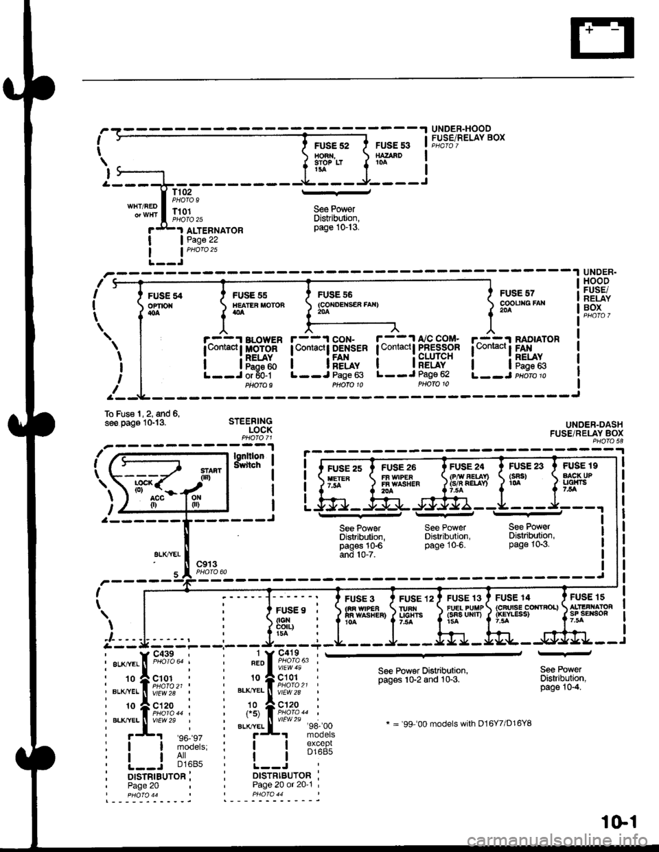
To Fus€ l, 2, and 6,see oaos lGl3. STEERINGLOCK
\
l,ut-a--- ---------J
gLXTYEI
FUSE 23(sRs)1(rA
Phofo 10
See PowerDistribdion,pagos 10€and 10-7.
FUSE 3tm w|PEain wAsr{ER}10A
PHOTO 10
See PowerDistribution,page 10-6.
FUSE 24(P,ry AEUn(s/n QELAY)
FUSE 13FU€L PUIIP(sns uRrT)15A
See PowerDisaibution,page 10-3.
FUSE 14{cFrrsE corrtRoL}{rcYLESS)
c913I
I
FUSE9 ,
FUSE 12IURI{UCHTS7,trA
) | , i ]si"ii:-' r|r::::---'--- J/--_-r
i::{;iil i i".ii.l ,#,;:|'-
i-:'ff1tu;.,,, i *=ft;;***
See Powsr Distribution,pages 10-2 and 10-3.
* = '99-'00 models with D16Y7/D16YB
Sea PowerDistribuiion,page 10-4.
:! iii'^': i i lB1%"f;
i L-=r -','lo' i !.---i..-^- ii orsrnrauron i i DtsrRtBUroR :' Page 20 Page 20 or 20'1 '
%[-#
I pHOfO 44 PHO|O 44
1Gl