relay HONDA CIVIC 1998 6.G Workshop Manual
[x] Cancel search | Manufacturer: HONDA, Model Year: 1998, Model line: CIVIC, Model: HONDA CIVIC 1998 6.GPages: 2189, PDF Size: 69.39 MB
Page 1620 of 2189
![HONDA CIVIC 1998 6.G Workshop Manual A/T Gear Position Indicator
UNDER.DASHFI.JSE/FELAY BOXIGNITIONswrrcH
Circuit Diagram
CW:
UNDER HOOD FUSE/RELAY BOX
6; |-;,,r&l \o3o75A
rr,/-TPLK+r,,rirac coJ-aL("E1.<\c-t]
---
IY. PCM"
:i3M)
V
I HONDA CIVIC 1998 6.G Workshop Manual A/T Gear Position Indicator
UNDER.DASHFI.JSE/FELAY BOXIGNITIONswrrcH
Circuit Diagram
CW:
UNDER HOOD FUSE/RELAY BOX
6; |-;,,r&l \o3o75A
rr,/-TPLK+r,,rirac coJ-aL("E1.<\c-t]
---
IY. PCM"
:i3M)
V
I](/img/13/6068/w960_6068-1619.png)
A/T Gear Position Indicator
UNDER.DASHFI.JSE/FELAY BOXIGNITIONswrrcH
Circuit Diagram
CW:
UNDER HOOD FUSE/RELAY BOX
6; |-;,,'r&l \o3o'75A
rr,/-TPLK+r,,'rirac coJ-aL("E1.<\c-t]
---
IY. PCM"
:i3M)''
V
ILT GRN
TqM 'l
f7v
tlYEL GFN
8LK
G401G442
*1 : 96'98 modeis+2 i '99t0 models
No 30 {7.5A)
V
IRED/BLK
t,
||l
| ,k sfi0f, |Itg)coNsotEl
I Y i1?ri I
tll
t'RED
I
I
vDASI| L GHTSERIGHTNESSCONTNOLLER
l./TGEAR POSITION INDICAToR (h lhe gauge assembty)
YYYY
A/TGEARPostTtoNswrTcH
A'/T GEAB POSITION NDICATOR OIMMING C]RCUIT
23-150
Page 1623 of 2189
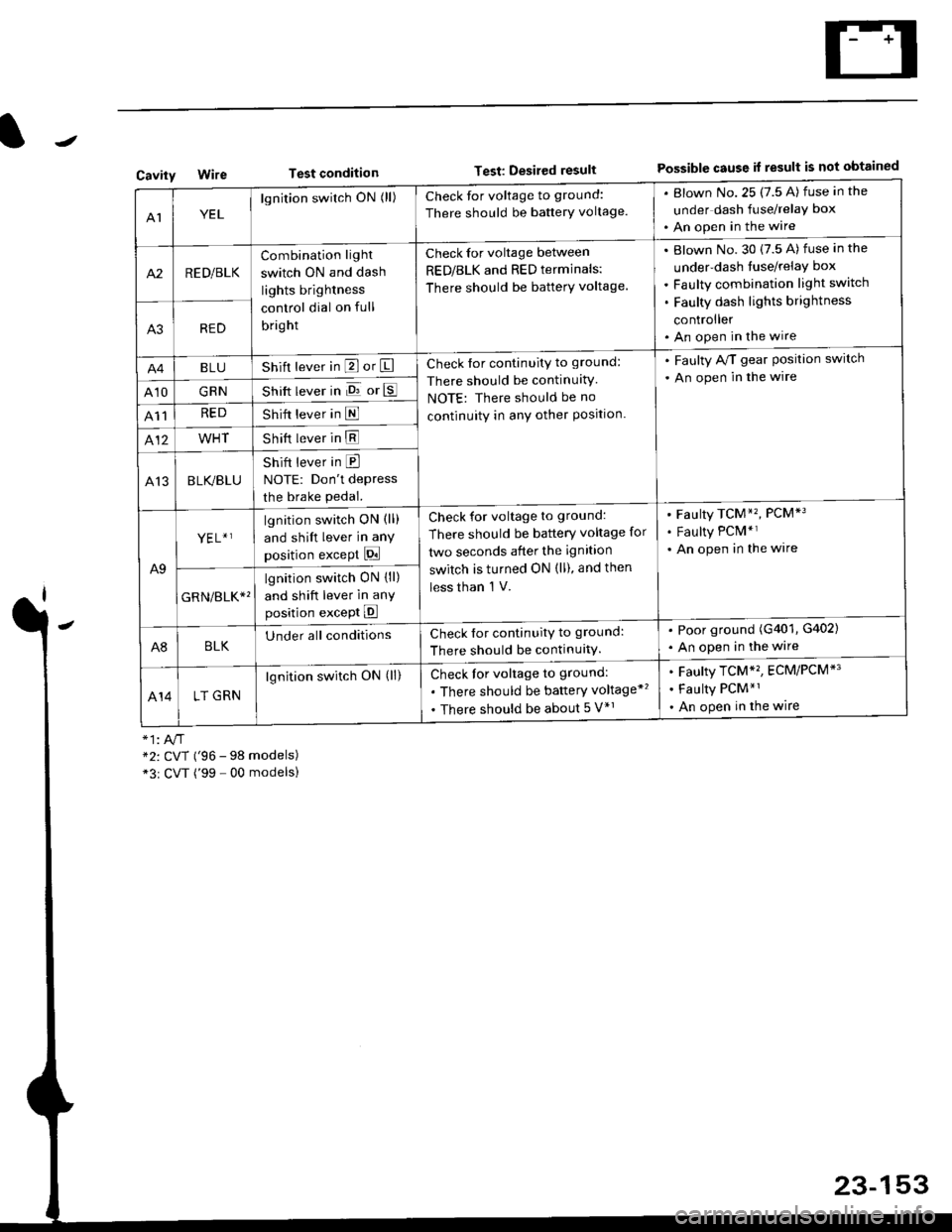
Test conditionTest: Desired resultPossible cause it result is not obtainedCavity
AIYEL
lgnition switch ON (ll)Check for voltage to ground:
There should be banerY voltage.
. Blown No.25 (7.5 A) fuse in the
under dash fuse/relay box
. An open in the wire
A2RED/BLK
Combination light
switch ON and dash
lights brightness
control dial on full
bright
Check for voltage between
RED/BLK and RED terminals:
There should be batterY voltage.
Blown No. 30 {7.5 A) fuse in the
under-dash tuse/relay box
Faulty combination light switch
Faulty dash lights brightness
controller
An open in the wireA3RED
BLUShift lever in P or ICheck for continuity to ground:
There should be continuitY
NOTE: There should be no
continuity in anY other Position.
. Faulty A/T gear Position switch
. An open in the wire
A10GRNShift lever in E or E
A11REDShift lever in E
412WHTShift lever in E
A13BLK/BLU
Shift lever in E
NOTE: Don't depress
the brake pedal.
A9
YEL+ ]lgnition switch ON (ll)
and shift lever in any
position except Pi
Check for voltage to ground:
There should be battery voltage for
two seconds after the ignition
switch is turned ON (ll), and then
less than 'l V.
Faulty TCM*'�, PCM*3
Faulty PCM*r
An open in the wire
GRN/err*'
lgnition switch ON {ll)
and shift lever in anY
position except E
A8BLKUnder all conditionsCheck for continuitv to ground:
There should be continuitY.
. Poor ground (G401, G402)
. An open in the wire
414LT GRN
lgnition switch ON (ll)Check for voltage to ground:
. There should be baftery voltage*'�
. There should be about 5 V*r
Faulty TCM*'�, ECM/PCM*'
Faulty PCM*1
An open in the wire
*2: CVT ('96 - 98 models)*3r CVT ('99 - 00 modelsl
23-153
Page 1626 of 2189
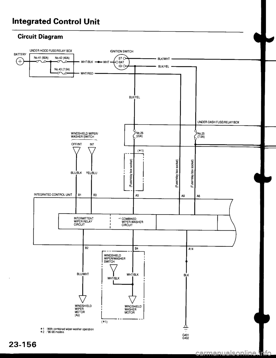
Integrated Control Unit
UNDER,DASH FUS€/RELAY 8OX
IGNITION SWITCH
I wNDSHTELD II wrPEtuwAsHEF II swrTcH I
i Y **i,,*I wHT,tsLK II t_+
JV
Circuit Diagram
INTEGRATED CONTROL UNIT
8LK
G40tG402
WINOSHIELD WIPER/WASHER S-W|iCI.] ,
OFF/INT INT
f7 Y7
IIlltl
ttBLU/BLK YEUELU
ELUMHT
I
I
WINDSHIELDWIPEBMOTOH(As)
* 1 : Wilh mmbrned wiper washer operalion*2 : 96-98 models
UNDES H@O FUSE/RELAY BOX
6
,8-q
INTEEMITTENTWIPER RELAYCIRCUIT
"J COMBINEOWIPER.WASHENctncutT
WINOSHIELDWASHERMOTOR
23-156
Page 1627 of 2189
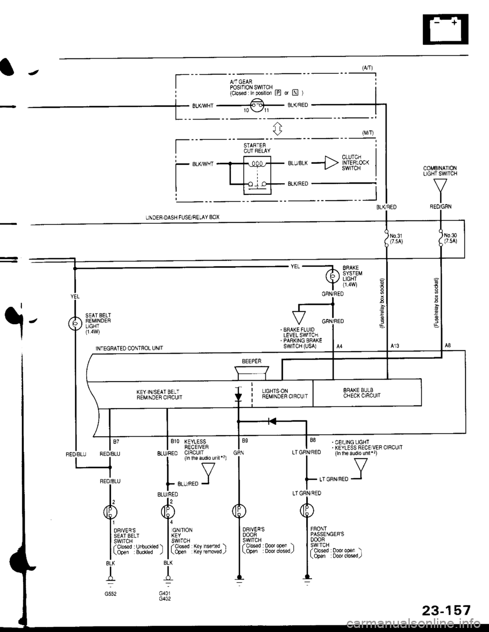
(A,4)
A,T GEARPosrfloN swlrcH _ _(Closed h posilon l?l ot [!l )
BLU/BLK -> [h'#f- |COMEINATIONLIGHT SWITCH
V
IREO/GRN
UNDEF.DASH FUSEi RELAY BOX
a
E
YEL
I
A iEi,I,B"'T
vll".i,l
| ,rr.nrorro .orrro, ,*,,
tt-
t(
rffi
|
BEMI\DEB crqcurl
lm
| /t I
tffinEoTsru REDTBLU BLIJ/RED clnculr
-neoieru | ,,-,r.0 J
l, "ulTo
/fP /Itr\
YVI onrveqs I or rtor
l3fifl&''' l5frl'.'
l (3'&T' 8iytr") l
(3&Y fiti'fJ"fl )
BLK BLK
TT
c552 G401
I
. BRAKE FLUIDLEVEL SWITCH. PARKING ERAKEswrTcH (usA)
' CEILING LIGHT. KEYLESS RECE VER CIRCUIT(ln lhe audio unil")
..aorr,rro Y
A
Iu$ut,""'
I3fif'�3#3trr,)-::
DRIVER'SDOOFswtTcHfolosed : Door open )(Open :Doordosed/
STARTERCUT FELAY
a
-
GFNi RED
23-157
Page 1628 of 2189
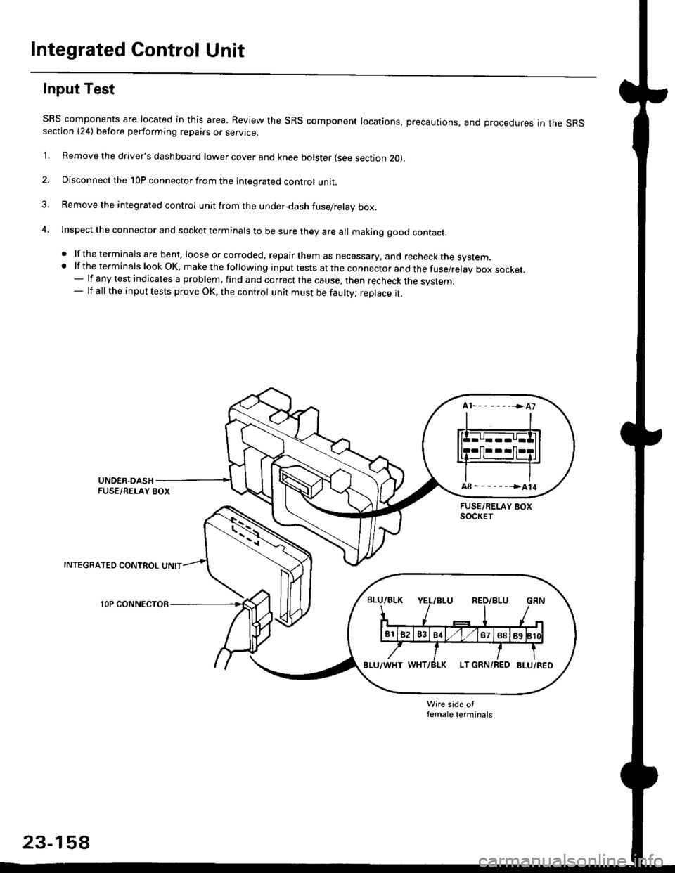
Integrated Control Unit
Input Test
SRS components are located in this area. Review the SRS component locations, precautions, and procedures in the SRSsection {24) before performing repairs or service.
1. Remove the driver's dashboard lower cover and knee bolster (see section 20),
2. Disconnect the 10P connector from the integrated control unit.
3. Remove the integrated control unit from the under,dash fuse/relay box.
4. lnspect the connector and socket terminals to be sure they are all makjng good contact.
. lf the terminals are bent, loose or corroded, repair them as necessary, and recheck the system..lftheterminalslookOK,makethefollowinginputtestsattheconnectorandthefuse/relayboxsocket.
- lf any test indicates a problem, find and correct the cause, then recheck the system.- lf all the input tests prove OK, the control unit must be faulty; replace it.
INTEGRATED CONTROL UNIT
lOP CONNECTOR
Wire side otfemale terminals
23-158
Page 1629 of 2189
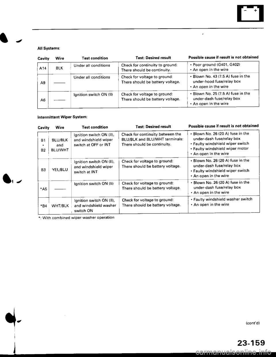
All Systems:
Cavity Wire
Cavity Wire
Intelmittent Wiper System:
Test condilion
Test condition
Test: Desired resultPossible cause il rgsull is not obtained
Test: Desired resultPossible cause if result is not obtained
Al4BLKUnder all conditionsCheck for continuity to ground:
There should be continuity.
. Poor ground (G401, G402). An open in the wire
A9
Under all conditionsCheck for voltage to ground:
There should be battery voltage.
. Blown No. 43 (7.5 A) fuse in the
under-hood fuse/relay box
. An open in the wire
A6
lgnition switch ON (ll)Check for voltage to ground:
There should be baftery voltage.
. Blown No. 25 (7.5 A) fuse in the
under-dash fuse/relay box. An open in the wire
B1
82
BLU/BLK
and
BLU,^/VHT
lgnition switch ON (ll),
and windshield wiper
switch at OFF or INT
Check for continuity between the
BLU/BLK and BLU/WHT terminals:
There should be continujty.
Blown No. 26 {20 A) fuse in the
under-dash fuse/relay box
Faulty windshield wiper switch
Faulty windshield wiper motor
An open in the wire
B3YEUBLU
lgnition switch ON (ll),
and windshield wiper
switch at INT
Check for voltage to ground:
There should be battery voltage.
Blown No.26 (20 A) fuse in the
under-dash fuse/relay box
Faulty windshield wiper switch
An open in the wire
*A5lgnition switch ON (ll)Check tor voltage to ground:
There should be battery voltage.
. Blown No.26 (20 A) fuse in the
under-dash fuse/relay box. An open in the wire
WHT/BLK
lgnition switch ON { ll),
and windshield washer
switch ON
Check for voltage to ground:
There should be battery voltage.
. Faulty windshield washer switch
. An open in the wire
*: With combined wiper'washer operatlon
{-(cont'd)
Page 1630 of 2189
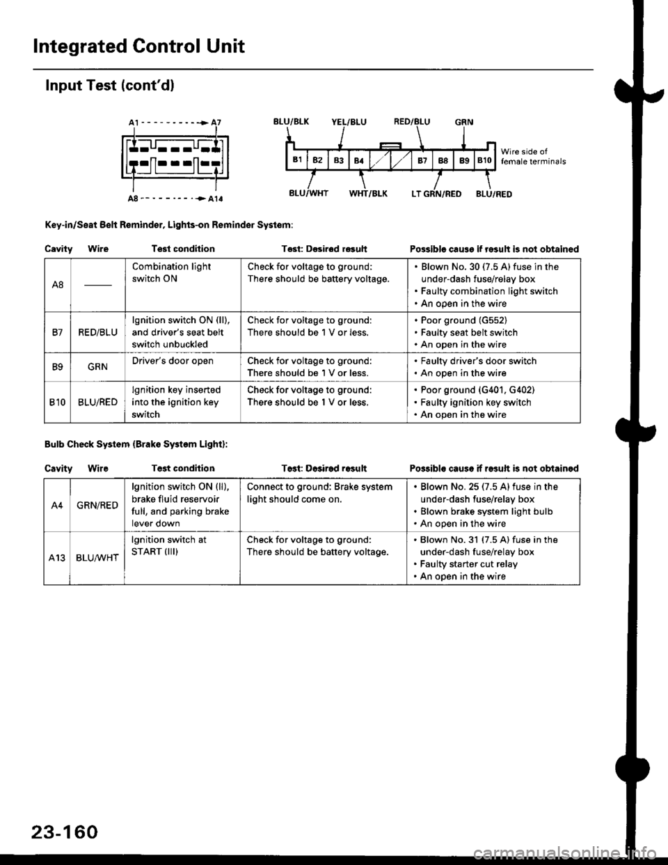
Integrated Gontrol Unit
Input Test (cont'dl
A8--------.--all
Key-in/Seat Belt R€mind€r, Lights-on Reminder Systom:
Cavity WireTest condhion
Bulb Check System (Brako System Light):
Cavity WireTest condilion
Tost: D€sirod r€guh
T6st: Dosirad result
Possible cause if result is not obtained
Possibls cause if rasuft b not obtainod
A8
Combination light
switch ON
Check for voltage to ground;
There should be battery voltage.
Blown No.30 (7.5 A)fuse in the
under-dash fuse/relay box
Faulty combination light switch
An open in the wire
B7RED/BLU
lgnition switch ON (ll),
and driver's seat belt
switch unbuckled
Check for voltage to ground:
There should be 1 V or less.
Poor ground (G552)
Faulty seat belt switch
An open in the wire
B9GRNDriver's door openCheck for voltage to ground:
There should be 1 V or less.
. Faulty driver's door switch. An open in the wire
Bl0BLU/RED
lgnition key inserted
into the ignition key
switch
Check for voltage to ground:
There should be 1 V or less.
Poor ground (G401. G402)
Faulty ignition key switch
An open in the wire
A4GRN/RED
lgnition switch ON {ll),
brake fluid reservoir
full, and parking brake
tever oown
Connect to ground: Brake system
light should come on.
Blown No.25 (7.5 Alfuse in the
under-dash fuse/relay box
Blown brake system light bulb
An open in the wire
A13BLUA/1r'HT
lgnition switch at
START (III)Check for voltage to ground:
There should be battery voltage.
Blown No.31 (7.5 A) fuse in the
under-dash fuse/relay box
Faulty starter cut relay
An open in the wire
23-160
Page 1632 of 2189
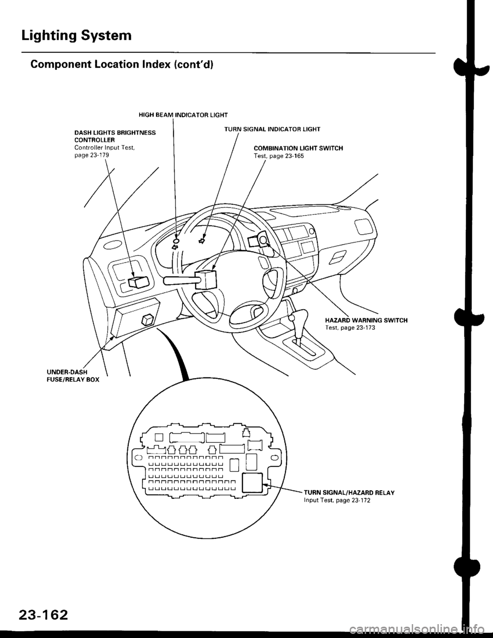
Lighting System
Gomponent Location Index (cont'dl
TURN SIGNAL INDICATOR LIGHTDASH LIGHTS BRIGHTNESSCONTROLLERController Input Test,page 23-119COMBINATION LIGHT SWITCHTest, page 23'165
TURN SIGNAL/HAZARD RELAYInput Test, page 23-'172
HIGH BEAM INOICATOR LIGHT
L ILI LILI LT
rr Lr rJ|r LJ Lr Lr rr !.r rr Lr rr I l-nnr1nr1r1r1r1|-1nn L JJ
r1 n11t'1n Ttr1 r1 - 11 t-1Tt-l T1r-t L.l Lt r-t r-t LJ ! ! LJ LJ ! LJ !J r-l
23-162
Page 1633 of 2189
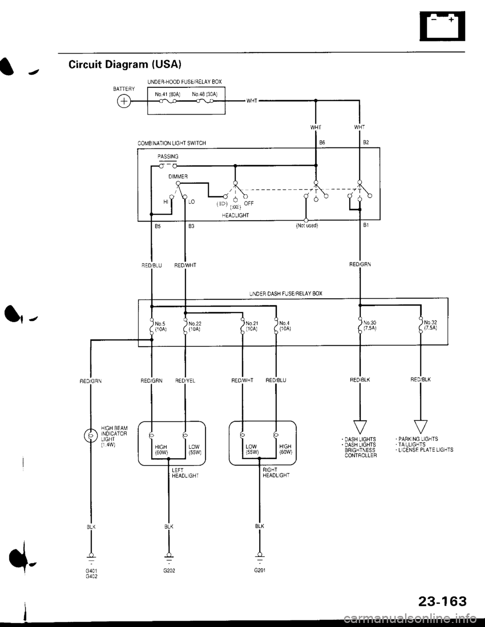
Circuit Diagram (USA)
l|-
RED/BLK
II
I
\?
PABK NG LIGHTSTA LL GHTSL CENSE PLATE L GHTS
RED/ELK
III
I
r'
DASH LIGHTSDASH LIGHTSERIGHTNESSCONTROLLER
HIGH BEAMIND CATORLIGHT(r 4w)
REDiGRN
I
BLK
I
G401G4A2
UNDER,HOOD FUSEi NELAY 8OX
'------ --.-r ----.'r
-T
I" T,,: i.. T
o
UNDER DASH FUSE/RELAY 8OX
No5(104)No.4004)No 30(7.5A)
I)N0.32A {7.5A)
I
No 22(r0A)
AT
lilffl (
II
BLK
I
G201
8LK
I
:
G202
23-163
Page 1634 of 2189
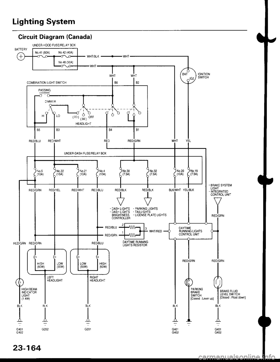
Lighting System
Circuit Diagram (Canada)
UNDER.HOOD FUSEi RELAY BOXBATTERY
BFAKE SYSTEMLIGHTNTEGRATEDCONTROL UNIT
f-7
I
IFED/GRN
REDiGFN
II
o
Yro*, ,,r'oI LEVEL SW TCH
t |
lclosed : Floal downl
BLK
I
-L..
G401G402
T
.:
BLK
n:
G40lG402
BLK
I
G201
RED/GRN RED/GBN
| .+_
ttL
| | las*,
| \_i-f
Alr
Y,o" r.o" I
liiqff'- |BLK BLK
tl
dT--
G401 G202G402
l\------tr -1
d,$,E" T d
RED/BLU RED/REDiGEN
UNDEF DASH FUSE/RELAY BOX
I
)) N0.20tl0Al)'
No.1g(7.5A)No.50 0A)
, ll-l
llltti /i[ii i,II
ll
llri, zll",ll iu"x
TT
FEDiGRN R€D
tl
!-tl--l
ttuLj
il]-
YEL REDTWHT FED/BLU FED/8LK RED/ BLK
tt++
IIVV| | .DASF L.GHTS . oAB(^rG -TGHTSI I .DAS-LGH'S.TALL'GCTS
| | 33''9+il4[','o L.ENSEoLATELTG'TS
I l-,ro,u,rffl,
^-^^-.*^,{*"'"0-
tlI qsnlq,rr DAYT'ME qUNNINGLIGHTS FES STOF
nd--f)
irt* | | Trt* Iorr Itt I---J \---J-------J
-rGHr
lt*"','
I
I
YEL/BLK
DAYTIMERUNNING LIGHTSCONTROL UNIT
RED/GHN R
I
5
[i.mi:-",,,