d16y5 HONDA CIVIC 1998 6.G User Guide
[x] Cancel search | Manufacturer: HONDA, Model Year: 1998, Model line: CIVIC, Model: HONDA CIVIC 1998 6.GPages: 2189, PDF Size: 69.39 MB
Page 66 of 2189
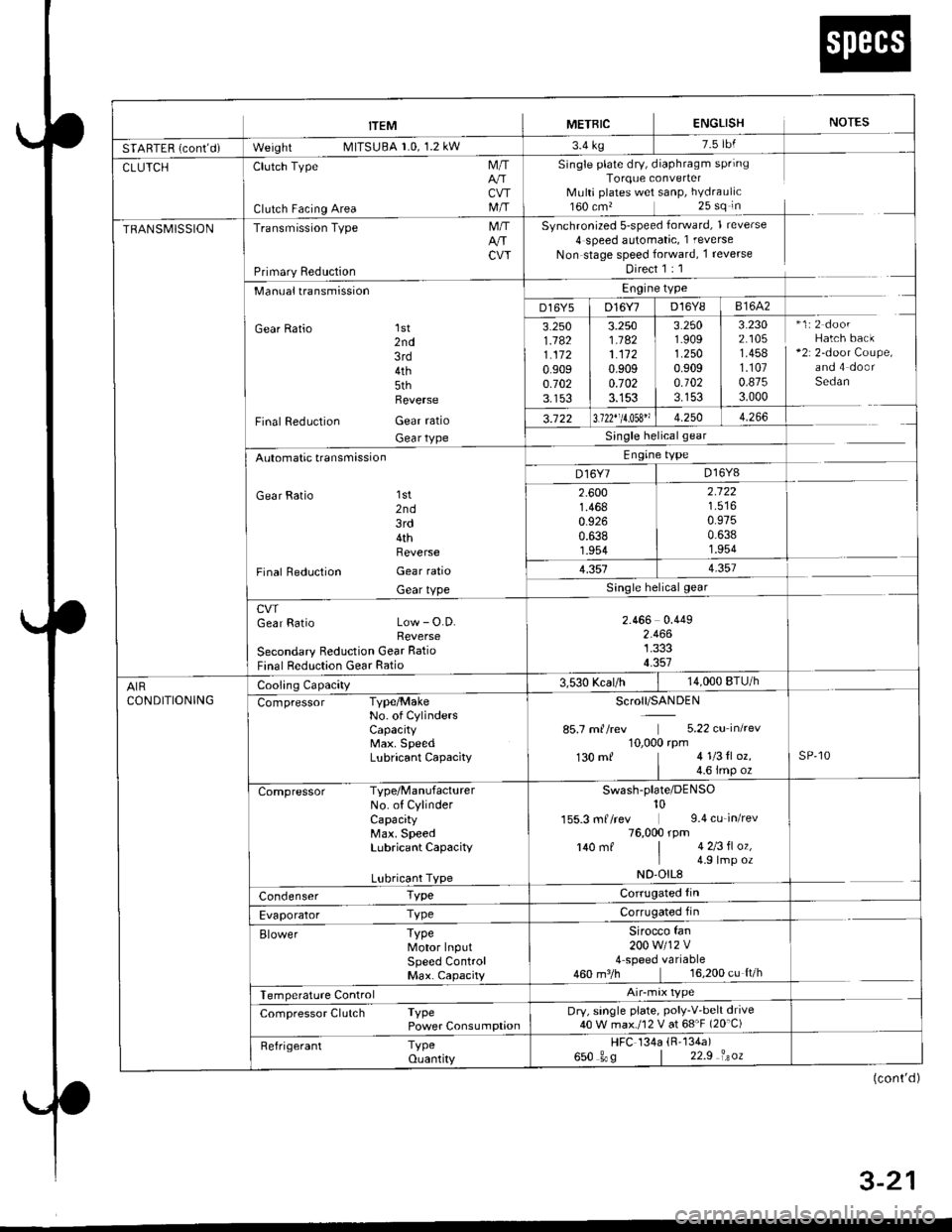
trEM I merntc ENGLISH NorEs
SfAnff n i*nt-i- W"'gf,t MllSUBA r.u, l.z kw r'4 rg
CLUTCHClutch Type
Clutch Facing Area
M/T
CVTM/T
Single plate dry, diaphragm springTorque converterMulti plates wet sanP, hYdraulic160 cm,25 sq in
Synchronized 5-speed forward, 1 reverse
4 speed automatic, 1 reverse
Non stage speed forward, 1 reverse
Direct 1 : 1
TRANSMISSIONTransmission Type
Primary Reduction
M/TArrCW
Manualtransmission
Gear Ratio 1st2nd3rd4th5thReverse
Final Reduction Gear ratio
Gear tYPe
Engine type
D16Y5 | D16Y7 D16Y8 I 81642
3.2501.1821.1120.9090.7023.153
3.2501.1821.1120.9090.7023.153
3.2501.9091.2500.9090.1023.153
3.2302.1051.4581.1070.8753.000
*1:2 doorHatch back+2r 2-door Coupe,and 4 doorSedan
3.122 13.122"11.053" 1 4.250 | 4.266
Single helicalgear
Engine type
D16Y7 | D16Y8Automatic transmission
Gear Ratio 'lst
2nd3rd4thReverse
Final Reduction Gear ratio
Gear tYPe
2.6001.4680.9260.6381.954
2.122
0.9750.6381.954
1.3514.357
cwGear Ratio Low - O.D.Reverse
Secondary Reduction Gear Ratio
Final Reduction Gear Ratio
2.466 0.4492.4661.3334.357
AIRCONDITIONING
Cooling Capacity3,530 Kcal/h14,000 BTU/h
Compressor Type/MakeNo. of CYlindersCaPacitYMax. SpeedLubricant CaPacitY
Scroll/SANDEN
85.7 m//rev 5.22 cu inkev10,000 rpm130 mf 41l3tl oz.
| 4.6 imp ozsP,10
Compressor Type/ManufacturerNo. of CylinderCapacityMax. SpeedLubricant CaPacitY
Lubricant TYPe
Swash-plate/DENso10155.3 mf /rev 9.4 cu_in/rev76,000 rpm140 mf | 4 2l3fl oz,I 4 9lmp ozND'OIL8
Condenser TypeCorrugated fin
Evaporator TyPeCorrugated fin
Elower TyPeMotor InputSPeed ControlMax. CaPacity
Sirocco fan200w112v4 speed variable460 m3/h 16,200 cu ft/h
Temperature Control
Compressor Clutch TyPePower ConsumPtionDry, single plate, PolY-V'belt drive40 W max./12 V at 68'F (20'C)
Refrigerant TyPeouantity
HFC 134a (R'134a)
650 gos | 22.9 isoz
(cont'd )
4 . J-Z I
Page 98 of 2189
Engine Removal/lnstallation
Removal (cont'dl
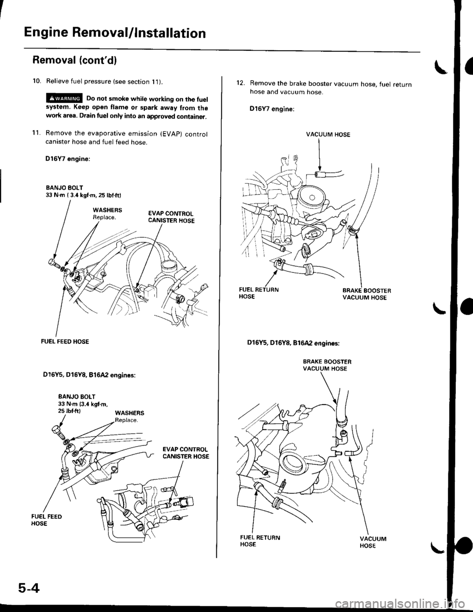
10. Relieve fuel pressure (see section l1).
!@ Do not smoke while working on the fuelsystem, Keep open flame or spark away from thewolk area. Drain fuel only inlo an approved container.
11. Remove the evaporative emission (EVAP) controlcanister hose and fuel feed hose.
D16Y7 engine:
BANJO BOLT33 N m ( 3.it lgt m, 25 lbt.ft)
FUEI- FEED HOSE
D16Y5, D16Y8, Bt642 engines:
5-4
I
12. Remove the brake
hose and vacuum
D16Y7 engine:
booster vacuum hose, fuel returnhose.
VACUUM HOSE
Dl6Y5, D16Y8, Bl642 enginos:
BRAKE BOOSTERVACUUM HOSE
Page 99 of 2189
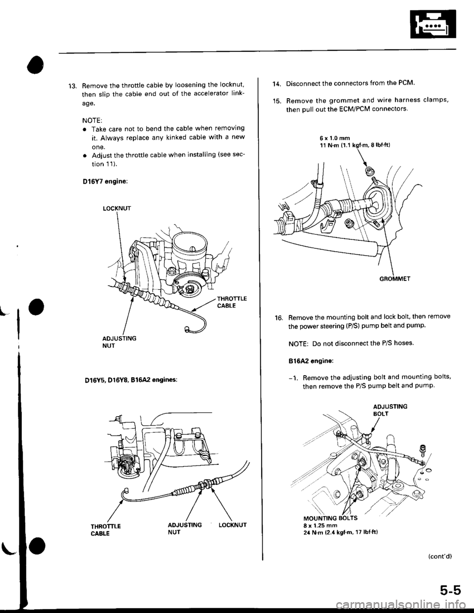
13. Remove the throftle cable by loosening the locknut,
then slip the cable end out of the accelerator link-
age.
NOTE;
. Take care not to bend the cable when removing
it. Always replace any kinked cable with a new
one.
. Adjust the throttle cable when installing (see sec-
tion 1 1).
D16Y7 engine:
D16Y5, D16Y8, B16A2 engines:
LOCKNUT
LOCKNUT
14,Disconnect the connectors from the PCM.
Remove the grommet and wire harness clamps,
then pull out the ECM/PCM connectors
6x1.0mm
16. Remove the mounting bolt and lock bolt, then remove
the power steering (P/S) pump belt and pump
NOTE: Do not disconnect the P/S hoses.
816A2 engine:
Remove the adjusting bolt and mounting boits,
then remove the P/S pump belt and pump
(cont'd)
5-5
AOJUSTING
Page 106 of 2189
Engine RemovaUlnstallation
Installation
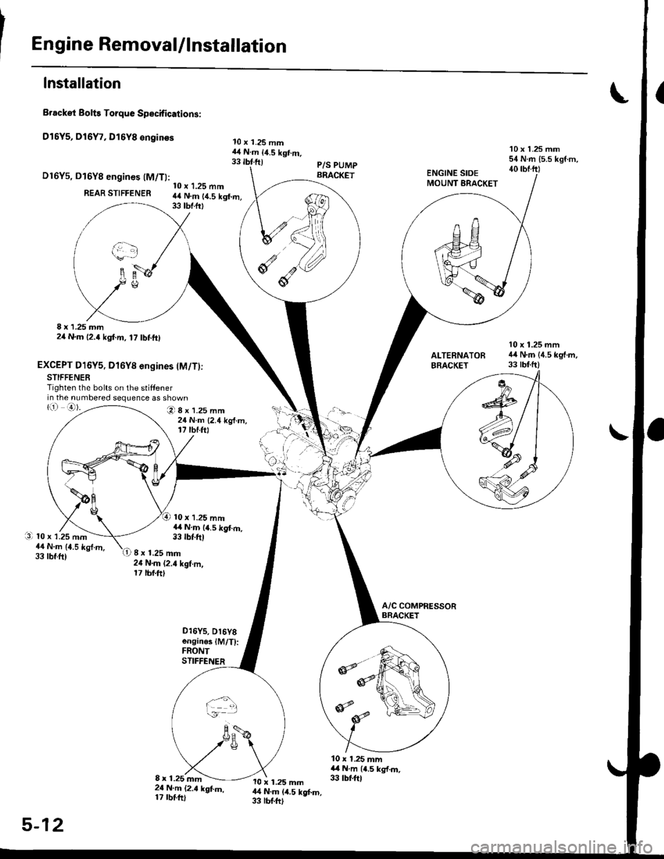
Brackei Bolts Torque Specifications:
Dl5Y5, Dl6Y7, Dl6Y8 €nginss
D16Y5, D16Y8 engines (M/Tl:
REAR STIFFENER
8 x 1.25 mm2/t N.m 12.4 kgf.m, 17 tbf.ftl
EXCEPT D16Y5, Dl6Yg engines lM/T)jSTIFFENERTighten the bolts on the stiffenerin the numbered sequence as shown
10 x 1.25 mm44 N.m 14.5 kgf.m,33 tbf.frt
O8x1.25mm24 N.m {2.4 kg{.m,17 tbr.ftt
10 x 1.25 mm14 N.m 14.5 kgt m,33 tbf.ft)
10 x 1.25 mm44 N.m {4.5 kgt m,33 tbr.ftl
10 x 1.25 mm54 N.m {5.5 kgf.m,40 rbf.ftl
10 x 1.25 mm44 N.m {4.5 kg'f.m,33 tbtftlALTERNATOFBRACKET
li) o).
l3l 10 x 1.25 mm44 N.m {1.5 kgt.m,33 tbt.ft)8 x 1.25 mm24 N.m (2.4 kgf.m,17 tbf.ft)
o16Ys, D16Y8enginoslM/T):FRONTSTIFFENER
10 x 1.25 mm4,4 N.m {4.5 kg{.m.33 tbf.ftl8 x 1.25 mm2{ N.m (2.t kgtm,17 rbtft)
10 x 1.25 mm14 N.m (4.5 kgf.m,33 lbf.ftl
5-12
Page 112 of 2189
Cylinder Head/Valve Train
Dl6Y5, D16Y7, Dl6Y8 engines
Special Tools ............. G2
VTEC Control System
Troubleshooting Flowchart .........." 6-3
VTEG Solenoid Valve
Inspection ............" 6-6
VTEC Rocker Arms
Manual lnspection
(D16Y5 engine) ............................. 6-7
Manual Inspection
(D16Yg enginel ................'............ 6-7
Inspection Using Special Tools
{D16Y5 engine} .....................""'... 6-8
Inspection Using Special Tools
(D16Y8 engine) .........................'.'. 6-10
Valve Clearance
Adiustment ..."".....6-12
Valve Seals
Replacement (Cylinder head removal
not requiredl ................................ 6-1tl
Crankshaft Pulley and PulleY Bolt
Replacement ."...... &16
Timing Selt
lllustrated Index ............................... 6-17
Inspection .............. 6-18
Tension Adjustment ........................ 6- 1 I
Removal ......,,......... 6-19
lnstallation ............. 6-20
Crankshaft Speed Fluctuation (CKF) Sensor
Repf acement .........6'22
Cylinder Head
lllustrated Index ............................... 6-23
Removal ................. 6-27
Warpage ................ 6-40
lnstallation ............. 6-45
Rocker Arms
Removal ................. 6-30
Disassembly/Reassambly ............... 6-31
Rocker Arms and Lost Motion Assemblies
Inspection (D16Y5, D16Yg
enginesl "..........' 5-34
Rocker Arms and Shafts
Glearance Inspection ....................... 6-35
Camshaft
Inspection .............. 6-36
Valves, Valve Springs and Valve Seals
Removal ........""..... 6-38
Valve Guides
Valve Movement .............................. 6-39
Replacement .........6-41
Reaming .......'......'.' 6-43
Valve Seats
Reconditioning .'....6'40
Valves
lnstallation ............. 6-tt3
Camshaft/Rocker Arms and
Camshaft Seal/Pulley
lnstallation ............. 6-44
Page 114 of 2189
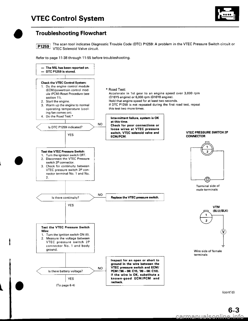
VTEC Control System
Troubleshooting Flowchart
tFtrsrl #ilH:::lj1t:"J:T,?ffnostic
rrouble code (Drc) Pr25e: A probrem in the vrEc Pressure switch circuit or
Reter to page 1 l-38 th roug h 1 1-55 before trou bleshooting.
* Road Test:Accelerate in 1st gear to an engine speed over 3,000 rpm(D16Y5 engine) or 6,000 rpm (D'16Y8 engine).Hold that engine speed for at least two seconds.It DTC P1259 is not repeated during the first road test, repeatthis test two more tames.
VTEC PRESSURE SWITCH 2PCONNECTOR
Terminal side ofmale terminals
Wire sid6 ol femalerermtnats
VTM
l1 (BLu/BLK)
f;-) |I
I
Y
I
The MIL has been reoorted on.DTC P1259 is sto.ed.
Check the VTEC Cont.ol Syst6m:1. Do the engine control module(ECM)/powertrain control module lPCM) Reset Procedure (see
section 11).2. Stan the engine.3. Warm up the engine to normaloperating temperature (cool-
ing fan comes on).4. Do the Boad Test.*Intermittont tailura, 3y3t.m is OKat thia time.Check for ooor connoctionr o.loose wirea at VTEC oiassurclwitch, VTEC solonoid valvo .ndECM/PCM,
ls OTC P1259 indicated?
Test rhe VTEC Prensure Switch:1. Turn the ignition switch OFF.2. Disconnect the VTEC Pressureswitch 2P connector.3. Check for continuity betweenVTEC pressure switch 2P con-nector terminal No. 1 and No.2.
Replace the VTEC preasure 3witch.ls there continuity?
Te3t the VTEC Pressure SwitchWire:1. Turn the ignition switch ON lll).2. Measure the voltage betweenVTEC press u re switch 2Pconnector No. l and bodyground.
In3poct for en opon or shod toground in thG wi.. bctwoon thoVTEC pro$ur6 switch rnd ECM/PCM l'96 - 9a: C15,'99 - 00: C101.lf tha wiro i3 OK,3ubrtitute aknown-good ECM/PCM andrecheck.
ls there battery voltage?
{To page 6'4i
Page 115 of 2189
I
VTEC Control System
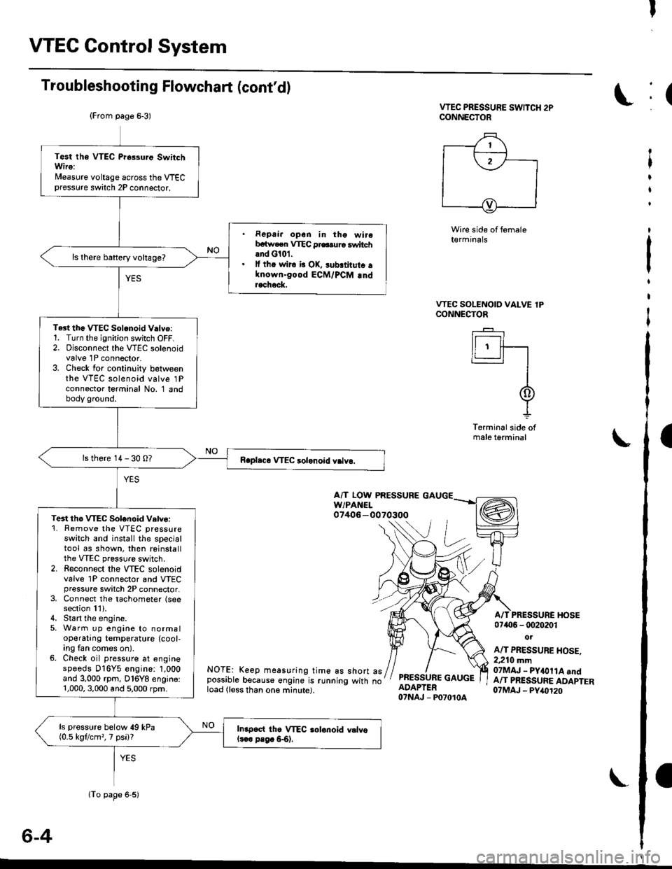
Troubleshooting Flowchart (cont'd)
VTEC PRESSURE SwlTCH 2PCONNECTOR
Wire side of female(€rmrnats
VTEC SOLENOID VALVE lPCONNECTOR
I r----'t I
ll ' ff---r'�-'�1
I
I
-L
Terminal side ofmale terminal
A/T LOW PRESSUREw/PAt{EL07406-0070300
NOTE: Keep measuring time as short aspossible because engine is running with noload (less than one minute).
PRESSURE GAUGEADAPTER07NAJ - P07010A
A/T PRESSURE I{OSE07406 - 0020201
ot
A/T PRESSURE HOSE.2,210 mm07MAJ - PY&llA andA/T PRESSURE ADAPTER07MAJ - PY,()120
6-4
(From page 6-3)
(To page 6-5)
Test the VTEC Pr6suro SwitchWiro:Nleasure voltage across the VTECpressure switch 2P connector.
. Rcpai. opon in tho wirebrtw.en VTEC pr6.urc switchand G101.. lf th. wir6 b OK, sub.thuto alnown-good ECM/PCM !ndracheck.
ls there baftery voltage?
Te3t the VTEC Solonoid V.lve:1. Turn the ignition switch OFF.2. Disconnect the VTEC solenoidvalve 1P connector.3. Check for continuity betweenthe VTEC solenoid valve 1Pconnector terminal No. 1 andbody ground.
ls there 14 - 30 0?
Te3t tho WEC Solonoid Vatvo:'1. Remove the VTEC pressureswatch and install the specialtool as shown, then reinstallthe VTEC pressure switch.2. Reconnoct the VTEC solenoidvalve 1P connector and VTECpressure switch 2P connector.3, Connect the tachometer (seesection 11).4. Stan the engine.5, Warm up engine to normaloperating temperature (cool,ing fan comes on).6. Check oil pressure at enginespeeds D16Y5 engine: 1,000and 3.000 rpm, D16Y8 engine:1,000,3,000 and 5,000 rpm.
ls pressure below 49 kPa(0.5 kgflcm,, 7 psi)?In.poct the VTEC aolonoid vllvols.c p.g. &6).
:(
t
I
t
:
t
I
I
Page 118 of 2189
VTEC Rocker Arms
2.
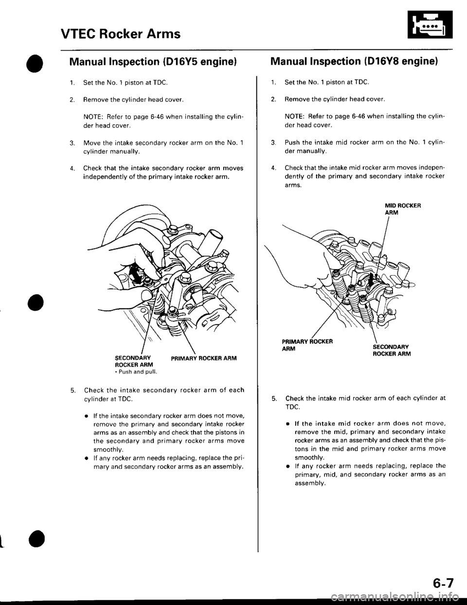
Manual Inspection (D16Y5 engine)
3.
1.
4.
Set the No. 1 piston at TDC.
Remove the cylinder head cover.
NOTE: Refer to page 6-46 when installing the cylin-
der head cover.
Move the intake secondary rocker arm on the No. 'l
cylinder manually.
Check that the intake secondary rocker arm moves
independently of the primary intake rocker arm,
SECoNDARY PtROCKER ARM. Push and pull.
Check the intake secondary
cylinder at TDC.
rocker arm of each
a lf the intake secondary rocker arm does not move,
remove the primary and secondary intake rocker
arms as an assembly and check that the pistons in
the secondary and primary rocker arms move
smoothly.
a lf any rocker arm needs replacing, replace the pri-
mary and secondary rocker arms as an assembly.
PRIMARY ROCKER ARM
4.
Manual Inspection (D16YB engine)
1.Set the No. 1 piston at TDC.
Remove the cylinder head cover.
NOTE: Reter to page 6-46 when installing the cylin-
der head cover.
Push the intake mid rocker arm on the No. 1 cylin-
der manually.
Check that the intake mid rocker arm moves indepen-
dently of the primary and secondary intake rocker
arms.
MID ROCKERARM
Check the intake mid rocker arm of each cylinder at
TDC,
lf the intake mid rocker arm does not move.
remove the mid, primary and secondary intake
rocker arms as an assembly and check that the pis-
tons in the mid and primary rocker arms move
smoothly.
lf any rocker arm needs replacing, replace the
primary, mid, and secondary rocker arms as an
assemory.
5,
6-7
Page 136 of 2189
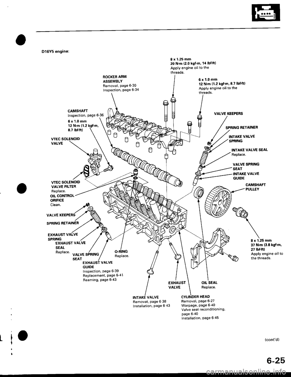
D16Y5 engine:
I x 1.25 mm20 N.m (2,0 kgf m, 14 lbf ft)
Apply engine oilto the
threads.ROCKEB ARMASSEMBLYFemoval, page 6-30
Inspection, Page 6-34
6x1.0mm12 N.m 11.2 kgf m, 8.7 lbf'ftl
Apply engine oilto the
threads.
VALVE KCEPERS
SPRING RETAINER
CAMSHAFTInspection, page 6-36
6x1.0mm12 N,m 11.28.7 tbf.ft)
WEC SOLENOIDVALVEBINTAKE VALVESPRING
INTAKE VALVE SEAL
Replace.
VALVE SPRINGSEAT
INTAKE VALVEGUIDE
CAMSHAFTPUL|'IY
VTEC SOLENOIDVALVE FILTERReplace.
OIL CONTROLORIFICEClean.
VALVE
SPRING RETAINEB
EXHAUST V
SPRING
VE
EXHAUST VALVE
SEALt"o'""".uoau,
SEATReplace.
GUIDEInspection, page 6-39Replacement, Page 6-41
Reaming, page 6-43EXHAUSTVALVEOIL SEALReplace.
HEAD
8 x 1.25 mm
37 N.m 13.8 kgf.m,
27 tbf.frlApply engine oiltothe lhreads.
(cont'd)
6-25
INTAKE VALVERemoval, page 6 38
Installalion, Page 6 43Removal, page 6-27Warpage, Page 6 40
Valve seat reconditioning'page 6-40lnstallation, page 6_45
Page 139 of 2189
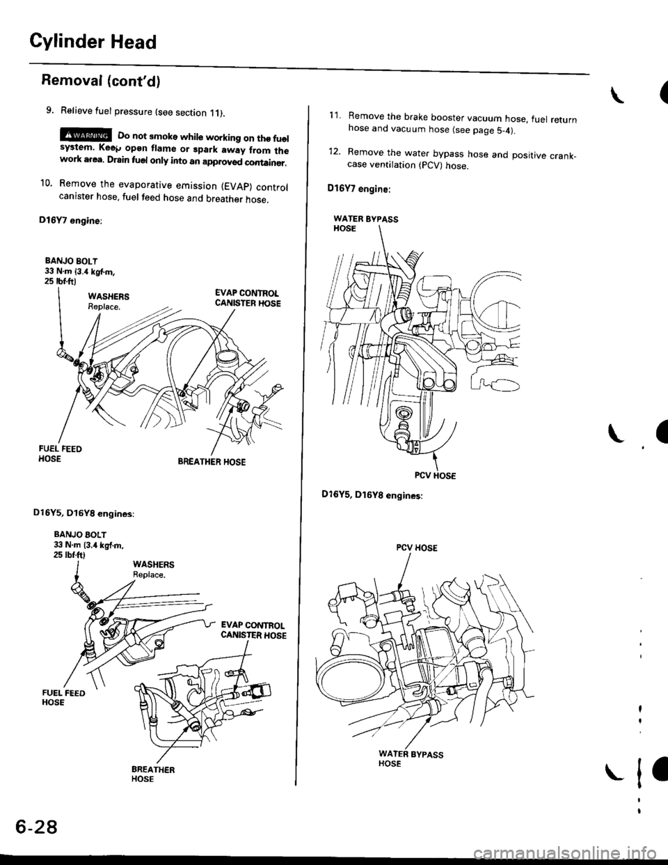
Cylinder Head
Removal (cont'd)
9. Relieve fuel pressure (see section 11),
E@E Do not smoke while working on tho fuelsystem. Ke6p opgn flame or gpark away from lhework area, Drain fuel only into an app.oved containgr.
10. Remove the evaporative emission (EVAP) controlcanister hose, fuel feed hose and breather hose.
D16Y7 engine:
BANJO BOLT33 N.m {3.4 kgt m,25 tbf.ftt
BREATHER HOSE
D15Y5, Dl6YB engines:
BANJO AOLT33 N.m (3.4 kgf.rn,25 tbf.ftt
EVAP CONTROLCANISTER HOSE
6-28
(
1 1. Remove the brake booster vacuum hose. fuel returnhose and vacuum hose (see page S_4).
12. Remove the water bypass hose and positive crank_case ventilation (pCV) hose.
016V7 engine:
PCV HOSE
D16Y5, D16Y8 engines:
\a
I
WATER EYPASS
PCV HOSE