d16y5 HONDA CIVIC 1998 6.G Repair Manual
[x] Cancel search | Manufacturer: HONDA, Model Year: 1998, Model line: CIVIC, Model: HONDA CIVIC 1998 6.GPages: 2189, PDF Size: 69.39 MB
Page 247 of 2189
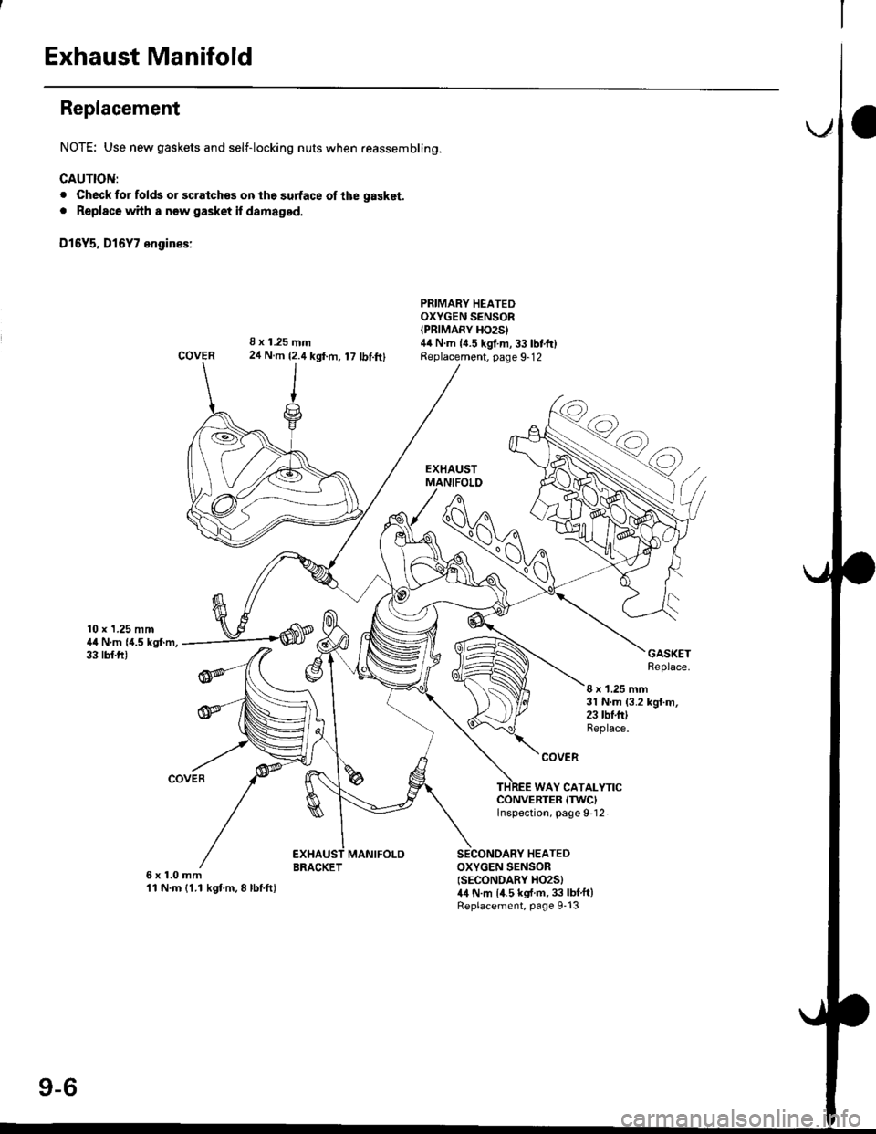
Exhaust Manifold
Replacement
NOTE: Use new gaskets and self-locking nuts when reassembling.
CAUTION:
. Check for folds or scratch€s on the surface of the gasket.
. Replace with a new gasket it damaged.
D16Y5. D16Y7 engines:
I x 1.25 mm24 N.m {2.4 kgt.m, 17 tbtft}
MANIFOLDBRACKET
PRIMARY HEATEDOXYGEN SENSORIPRIMAFY HO2SI44 N.m {4.5 kgf m, 33 lbtft)Replacement, page 9-12
GASKETReplace.
I x 1.25 mm31 N.m (3.2 kgf.m,23 tbf.ft)Beplace.
WAY CATALYTICCONVERTER {TWCIlnspection, page 9'12
6x1.0mm11 N.m {1.1 kgt m,8 lbf.ft)
SECONDARY HEATEDOXYGEN SENSOR(SECONDARY HO2S}44 N.m 14.5 kgf.m,33 lbf.ft)Replacement, page 9-13
9-6
Page 250 of 2189
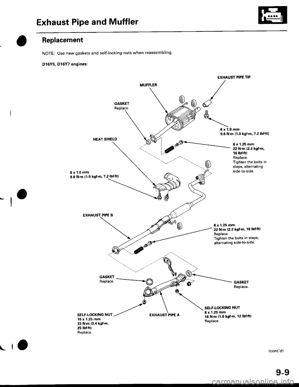
Exhaust Pipe and Muffler
\
Replacement
NOTE: Use new gaskets and self-locking nuts when reassembling
D16Y5, D16Y7 engines:
HEAT SHIELO
6x1.0mm9.8 N.m tl.0 kgf'm,7.2lbf'ft)
EXHAUST PIPE B
EXHAUST PIPE TIP
/
O
6x1.0mm9.8 N.m 11.0 kgt m, 7.2 lbf'ftl
oP----------------8 x 1.25 mm22 N.m 12.2 kg .m,
16 tbf.f Replace.Tighlen the bolts insteps, alternatingside to-side.
8 x 1.25 mm22 N.m 12.2 kgl'm, 16lbl'ttl
Replace.Tighten the bolts in steps,
alternating side-to-side
GASKETReplace.
SELF-LOCKING NUT
8 x 1.25 mm16 N.m 11.6 kgt m, 12 lbt'ftl
Replace.
(cont'd)
9-9
MUFFLER
neOlace. ----------"+@
SELF.LOCKING NUT10 x 1.25 mm33 N.m (3.4 ksd.m,25 lbf.frlReplace.
Page 253 of 2189
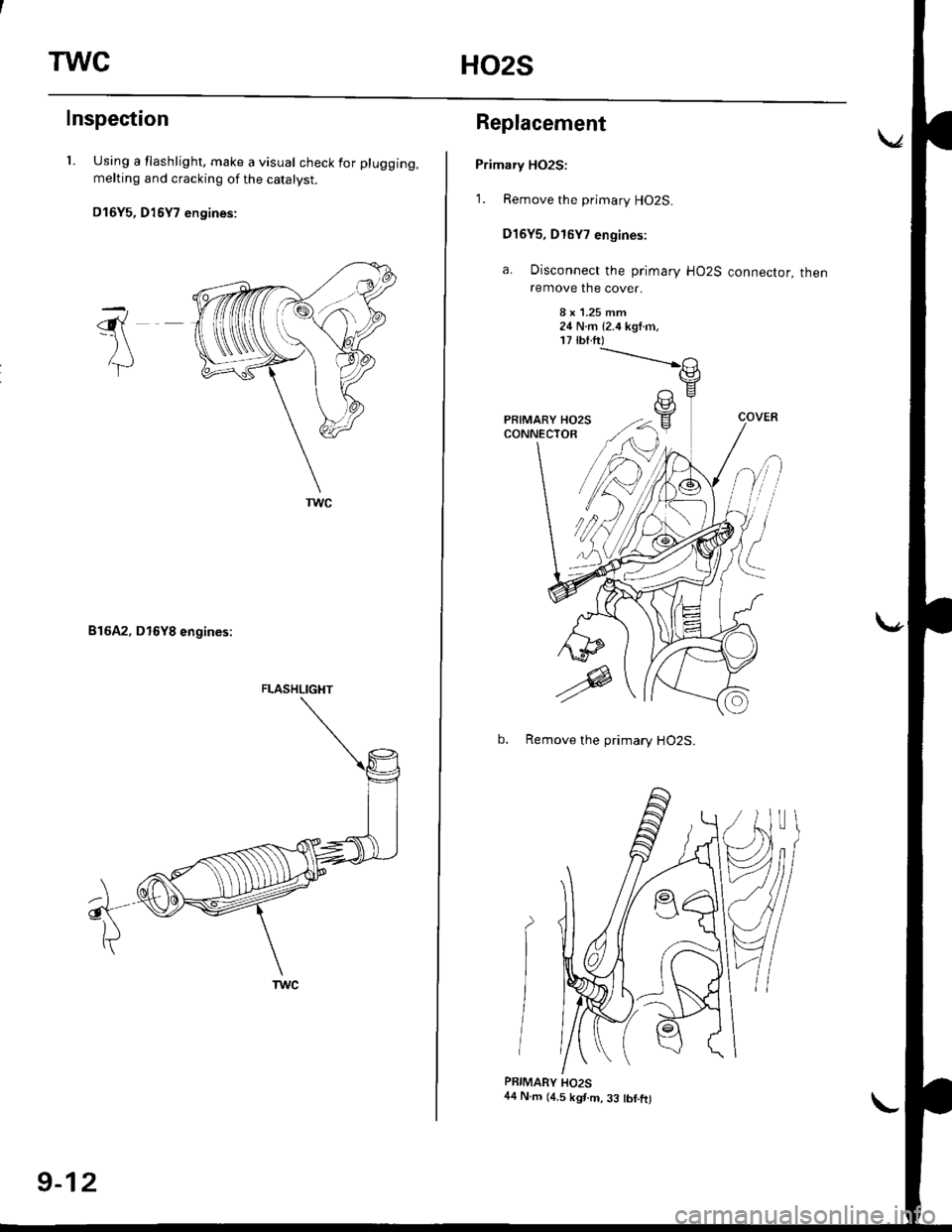
TWCHO2S
Inspection
l. Using a flashlight, make a visual check for plugging,
melting and cracking of the catalyst.
D16Y5, D16Y7 engines:
816A2, D16Y8 engines:
-\6{-)\
lT
a
A
FLASHLIGI{T
9-12
Replacement
Primary HO2S:
1. Remove the primary HO2S.
D16Y5, D15Y7 engines:
a. Disconnect the primary HO2S connector, thenremove the cover.
8 x'1.25 mm24 N.m {2.4 kgl.m,
PRIMARY H02SCONNECTOR
b. Remove the primary HO2S.
| \l ,l(
I bK/l
l llw.
/
(
PBIMARY HO2S44 N m (4.5 kgf.m, 33 tbI.ft)
Page 257 of 2189
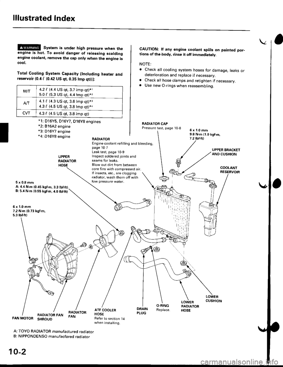
lllustrated Index
@@ system is under high pressure when theengine is hot. To avoid dangsr of rsleasing scaldingengine coolant, removo the cap only when the engine iscoot.
Total Cooling System Capacity flncluding heater andfoservoir (0.4 f (0.42 US qt, 0.35 tmp qt)ll:
*2: 81642 engine*3: D16Y7 engine*4: D16Y8 engine
CAUTION: lf any engine coolant spills on painted por-tions of the body, rinse it off immediately.
NOTE:
. Check all cooling system hoses for damage, leaks ordeterioration and replace if necessary.. Check all hose clamps and retighten if necessary.. Use new O-rings when reassembling.
RADIATOR CAPPressure test, page '10 86x1.0mm9.8 N.m {1.0 kgtm,7.2 tbt.ltl
UPPERRADIATORHOSE
UPPER BRACKETAND CUSHION
COOLANT
RAOIATOREngine coolant refilling and bleeding,page 10 7Leak test, page 10-9Inspect soldered joints andseams for leaks,Blow out dirt Irom betweencore fins with compressed air.lf insects, etc,, are cloggingradiator, wash them off withrow pressure water.
RESERVOIR
5x0.8mmA: ,1.4 N.m {0.45 kgf.m, 3.3 tbtftlg: 5.4 N.m (0.55 kgtm.4.0 tbf.ft)
6x1.0mm7.2 N.m (0.73 kgt.m,5.3 tbtftl
LOWERCUSHION
RADIATOR FANBADIATORFAN
DRAINPLUG
O-RINGReplace.
LOWEBRADIATORHOSE
FAN MOTOR SHROUD
Ar TOYO RADIATOR manufactured radiatorB: NIPPONDENSO manufacfared raoraror
10-2
Refer to section 14when installing.
Mt-|-4.2 f (4.4 US qt,3.7 tmp qt)*j
5.0 / (5.3 U$ q1, 4.4 16p q11*z
4.1 f (4.3 US qt, 3.6 lmp q0*3
4.31 (4.5 US qt, 3.8 tmp qt)*a
CVT4.3 f (4.5 US qt,3.8 Imp qt)
*1i D16Y5, D16Y7, D16Y8 engines
iil
Page 259 of 2189
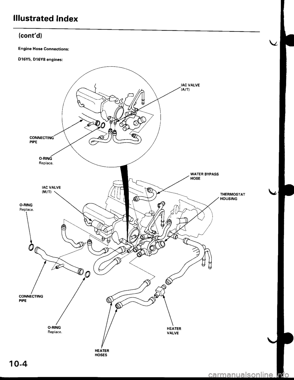
lllustrated Index
(cont'd)
Engine Hose Connections:
D16Y5, D16Y8 engines:
Replace.
IAC VALVE(M/TI
IAC VALVE{A/T)
WATER BYPASSHOSE
THERMOSTATHOUSING
O.RINGReplace.
\
\
\
\h
CONNECTINGPIPE
HEATERVALVE
HEATERHOS€S
10-4
Page 262 of 2189
tl
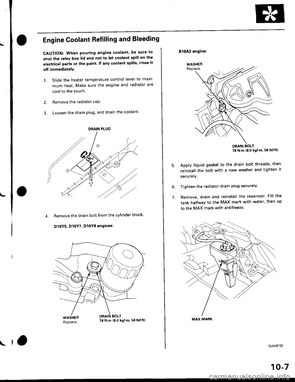
Engine Coolant Refilling and Bleeding
CAUTION: when pouring engine coolant, be sure to
shut the relay box lid and not to lst coolant spill on the
eleqtrical parts or the paint. lf any coolant spills, rinse it
off immediately.
1. Slide the heater temperature control lever to maxl-
mum heat. Make sure the engine and radiator are
cool to the touch.
Remove the radiator caP.
Loosen the drain plug, and drain the coolant'
Remove the drain bolt from the cylinder block'
D16Y5. D16Y7, Dl6Yg sngines:
DRAIN PLUG
0d
I ro
78 N.m {8.0 kgl m.58lbt'ft)
6.
1.
B1642 engin€:
WASHERReplace.
DRAIN BOLT78 N m (8 0 kgf m' 58lbfft)
Apply liquid gasket to the drain bolt threads, then
reinstall the bolt with a new washer and tighten 't
securely.
Tighten the radiator drain plug securely
Remove, drain and reinstall the reservoir' Fill the
tank halfway to the MAX mark with water, then up
to the MAX mark with antitreeze.
(cont'd)
10-7
MAX MARK
Page 263 of 2189
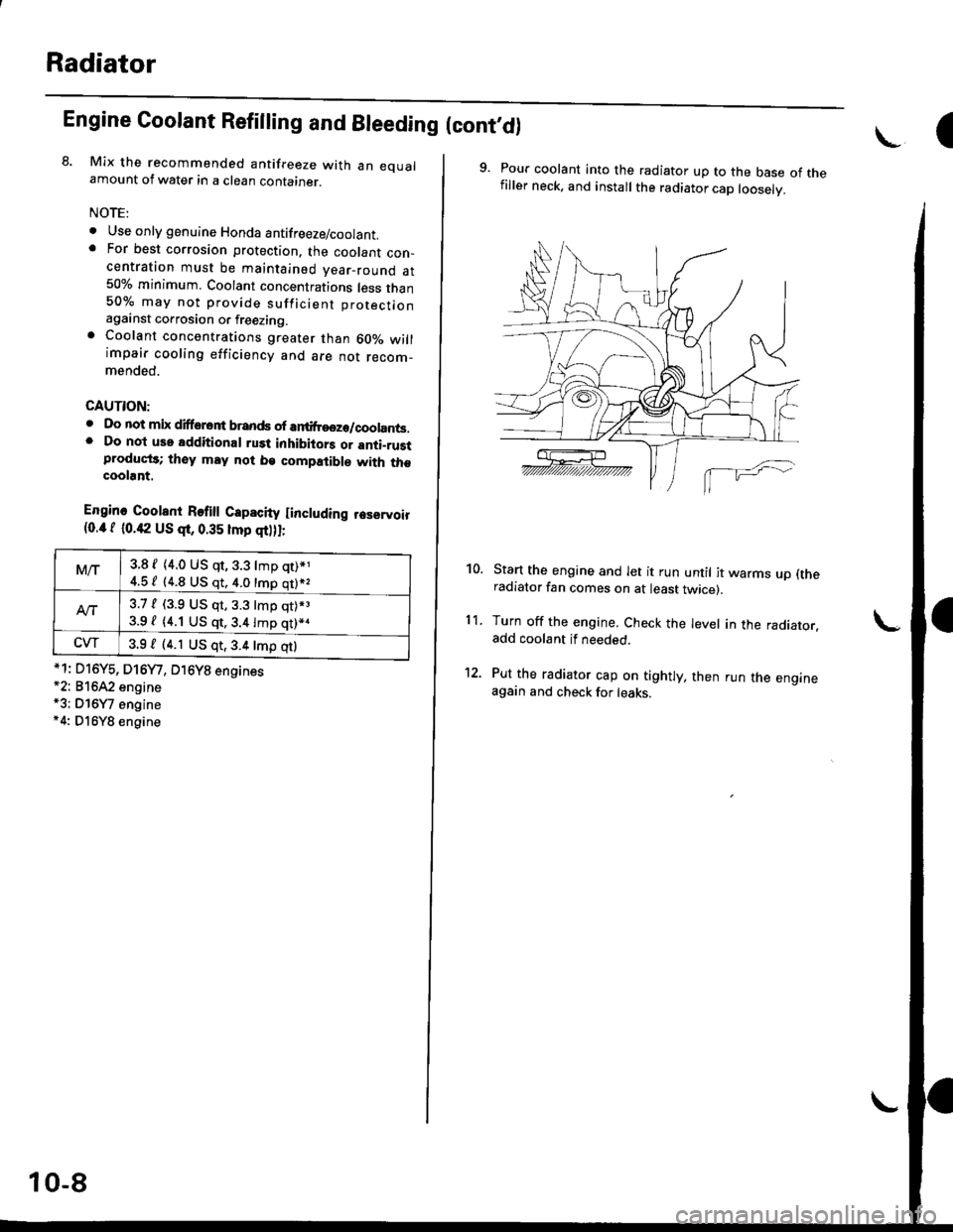
Radiator
Engine Coolant Refilting and Bleeding (cont,dl
8. Mix the recommended antifreeze with an eoualamount of water in a clean container.
NOTE:
o Use only genuine Honda antifreeze/coolant.. For best corrosion protection. the coolant con_centration must be maintained year_round at50% minimum. Coolant concentrations less than50% may not provide sufficient protectionagainst corrosion or freezing.. Coolant concentrations greater than 60010 willimpair cooling efficiency and are not recom_mended.
CAUTION:
. Do not mix difforont brands ofar ilreeze/coolants.. Do not use additional rust inhibiiors or anti_rustproduqt3; they may not be compatible with thecoolant.
Engine Coolent Refi
Capacity Iincluding reservoir{0.4 f 10.42 US qr, 0.35 lmp qt),I;
*1: D16Y5, D16Y/, O16Y8 engines*2: 81642 engine*3; Dl6Y7 engine*4: Dl6Y8 engine
M/r3.8 f {4.0 US qt, 3.3 lmp qt)*1
4.5 / (4.8 US qt. 4.0 tmp qt)*,
Att3.7, (3.9 US qr,3.3 tmp qt).3
3.9 / (4.1 US qt,3.4lmp qt)*.
CW3.9 / (4.1 US qt,3.4 tmp qtl
10-8
\.-I
9. Pour coolant into the radiator up to the base of thefiller neck. and install the radiator cap looselv.
Start the engine and let it run until it warms up (theradiator fan comes on at least twicer.
Turn off the engine. Check the level in the radiator.add coolant if needed.
Put the radiator cap on tightly, then run the engineagain and check for leaks.
10.
11.
Page 269 of 2189
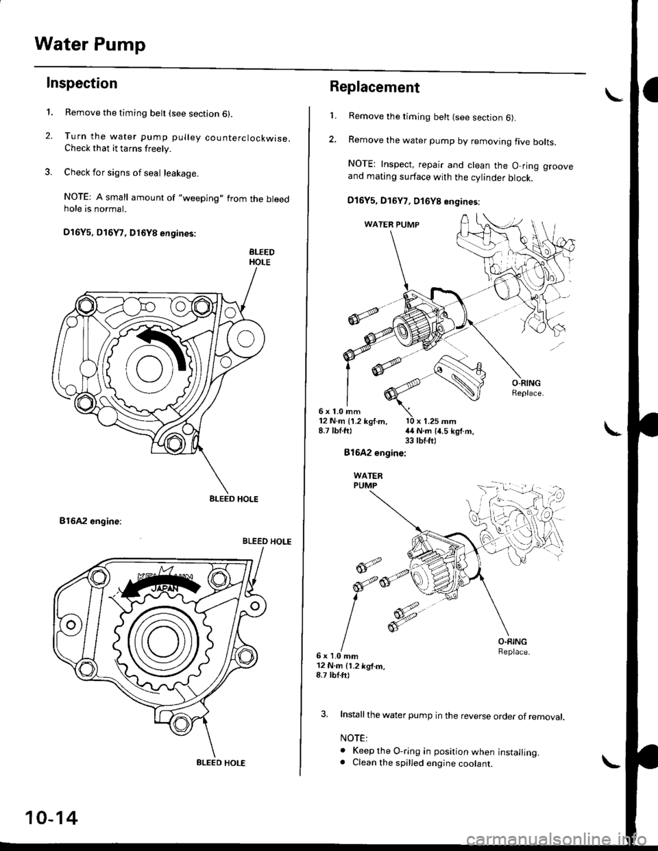
Water Pump
Inspection
't.
2.
Remove the timing belt (see section 6).
Turn the water pump pulley counterclockwise.Check that it tarns freely.
Check for signs of seal leakage.
NOTE: A small amount of "weeping,,from the bleedhole is normal.
Dl6Y5, Dl6Y7, D16Y8 engines:
BLEEDHOLE
B16A2 engine:
BLEED HOLE
BLEED HOLE
BLEED HOLE
10-14
Replacement
6x1.0mm
1.Remove the timing belt (see section 6).
Remove the water pump by removing five bolts.
NOTE: Inspect, repair and clean the O-ring grooveand mating surface with the cylinder block.
D16Y5, D16Y7, D16Y8 engines:
12 N.m {1.2 kgf.m, l0 x 1.25 mm8.7 lbt.ft) {4 N.m 14.5 kg{.m.33 tbt.ft)
Bl642 engine:
WATERPUMP
@;2
6x1.0mm12 N.m 11.2 kg{.m,8.7 tbf.ft)
O.RINGReplace.
3. Install the water pump in the reverse order of removal.
NOTE:
o Keep the O-ring in position when installing.. Clean the spilled engine coolant.
d
orp,
I
Page 272 of 2189
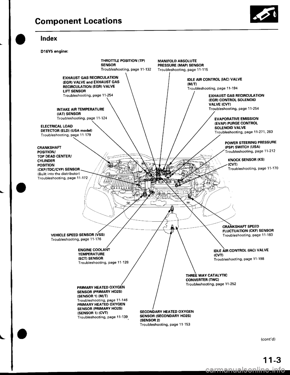
Gomponent Locations
L
lndex
D16Y5 engine:
{IATISENSORTroubleshooting,
ELECTRICAL LOADDETECTOR IELD) (USA mod6l)Troubleshooting, page 11 179
THROTTLE POSITION ITP)SENSORTroubleshooting, page 1 1-132
MANIFOLD ABSOLUTEPRESSURE IMAPI SENSORTroubleshooting, page 1'l-115
EXHAUST GAS RECIRCULATION
IEGRI VALVE and EXHAUST GAS
RECIRCULATION IEGRI VALVE
LIFT SENSORTroubleshooting, page'l 1-254
INTAKE AIR TEMPERATUR€
IDLE AIR CONTROL (IAC) VALVE
{M/T)Troubleshooting, page 1 1-194
EXHAUST GAS RECIRCULATION{EGRI CONTROL SOLENOIDVALVE ICW)Troubleshooting. page 1 1-254
EVAPORATIVE EMISSIONIEVAPI PUNGE CONTROLSOLENOID VALVETroubf eshooting, Page 1 1'21 1, 243
CRANKSHAFTPOS|TTON/TOP DEAD CENTER/CYLINDERPOS|T|ON
POWER STEERING PRESSURE(PSP) SWITCH (USAI
Troubleshooting, Page 1 1-212
KNoCK SENSoR (Ks)
(cwl
Troubleshooting, Page 1 1'170ICKP/TDC/CYP} SENSOR(Built into the distributor)Troubleshooting, Page 1 1'172
VEHICLE SPEED SENSORTroubleshooting, Page 1 1-176
FLUCTUATION (CKF} SENSOR
Troubleshooting, Page 1 1 -183
ENGINE COOLANTTEMPERATUREIECT) SENSORTroubleshooting, Page 11 128
IDT.ECONTROL IIACI VALVE
{cw)Troubleshooting, Page 11 198
WAY CATALYTICCONVERTER ITWCITroubleshooting, Page 1 1-252PRIMARY TIEATEDSENSOR {PNIMARY HO2SI
tsENsoR 1t {M/TlTroubleshooting, Page'l 1-146
PRIMARY HEATED OXYGENSENSOR (PRIMARY HO2SI
tsENsoR 1l {cw}Troubleshooting, Page 1 1-139
SECONDARY HEATED OXYGENSENSOR {SECONDARY HO2S){SENSOR 2)Troubleshooting, page 11 153
(cont'd)
1 1-3
Page 277 of 2189
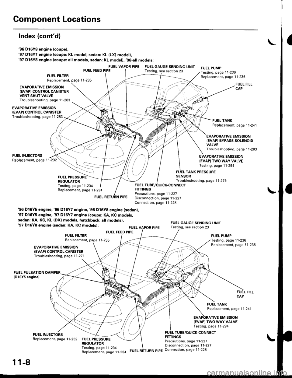
Component Locations
Index (cont'dl
'96 D16Y8 engine (coupel,'97 D16Y7 engine (coupe: KL model, sedan: KL (LXl model),'97 D16Y8 engine (coupe: all models, sedan: KL modell,'98-all models:
FUEI- VAPOR PIPEFUEL FEED PIPEFUEL GAUGE SENDING UNITTesting, see section 23FUEL PUMPTesting, page 11 236Replacement, page 11 236FUEL FILTERReplacement,
€VAPOFATIVE EMISSION(EVAPI CONTROL CANISTERVENT SHUT VALVETroubleshooting, page l1'283
FUEL FILLCAP
FUEL TANKReplacement, page I l-241
EVAPORATIVE EMISSIONIEVAPI CONTROLCANISTERTroubleshooting, page 11 283
EVAPORATIVE EMISSIONIEVAP) BYPASS SOLENOIDVALVETroubleshooting, page 1 1 -283
FUEL INJECTORSReplacement, page 1 1-232EVAPORATIVE EMISSION(EVAPI TWO WAY VALVETesting, page 11 294
FUELREGULATORTesting, page 11-234
TANK PRESSURESENSORTroubleshooting, page 11-275
Replacement, page 1 1-234
'96 Dt6Y5 engine,'96 D16Y7 engin€, '96 D16Y8 engine (sedanl,'97 D16Y5 engine,'97 Dl6Y7 engins (coupe: l(A, KC models,
sedan: KA, KC, KL (DXl models, hatchback: all models),'97 Dl6Y8 engine (sedan: KA, KC modelsl:
FUEL FEED PIPE
FUELFITTINGSPrecautions, page 1 1-227Disconnection, page 11 227Connection, page 11-228
FUEL VAPOR PIPE
FITTINGS
EVAPORATIVE EMISSIONIEVAPI CONTROL CANISTERTroubleshootiog, page 1 1-271
FUEL FILTERReplacement, page 1 1-235FUEL PUMPTesting, page 11-236Replacement, page 11-236
FUEL TANKBeplacement, page 11 241
TIVE EMISSION{EVAP) TWO WAY VALVETesting, page 11-294
TUBE/OUICK.CONNECT
FUEL PRESSUREREGULATORTesting, page 11'234Beplacement, page 11 234
Precautions, page 1 1-227Disconnection, page 11'227Connection, page 1 1-228
11-8
FUEL RETURN PIPE