d16y7 coolant HONDA CIVIC 1998 6.G User Guide
[x] Cancel search | Manufacturer: HONDA, Model Year: 1998, Model line: CIVIC, Model: HONDA CIVIC 1998 6.GPages: 2189, PDF Size: 69.39 MB
Page 363 of 2189
Troubleshooting
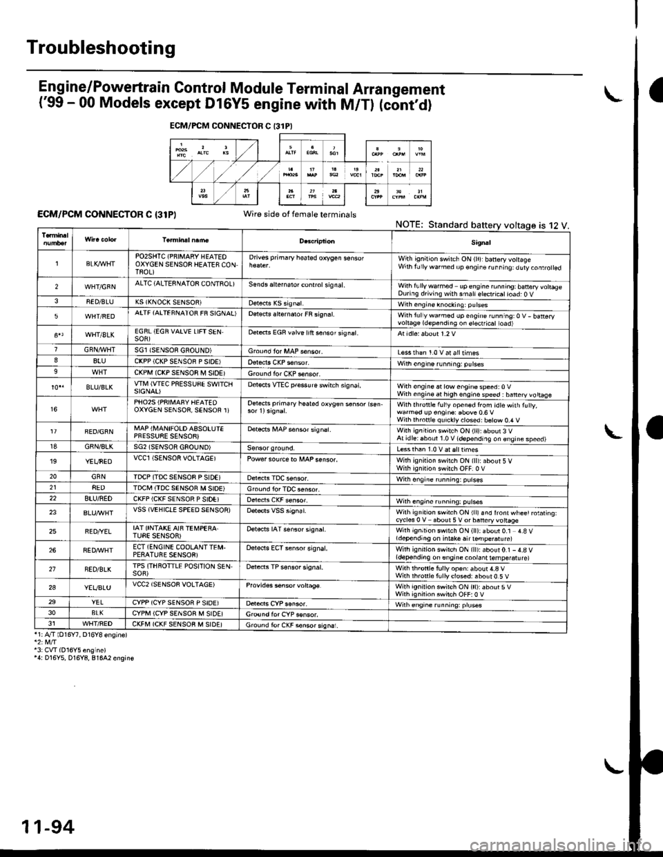
Eng ine/P_owertrain Control Module Term inal Arrangement
('99 - 00 Models except Dl6Y5 engine with M/Tl (cont,d)
ECM/PCM CONNECTOR C {31P)Wire side of female terminalsNOTE;Standard
*1;4"/T lD16Y7, D16Y8 ensinel
43: CVI(016Y5 engine)'4: D16Y5, D16Y8, 81642 engin€
ECM/FCM CONNECTOR C 13lPI
is 12 V.
Sig.al
lBLK4/VHTPO2SHTC (PNIMARY HEATEOOXYGEN SENSOB HEATES CONTROL)
Drivss primary hoated orygen sensofWith ignition switch ON (lr)rbanery volageWrh fJly warned up €ngir. ru..i19: duty.oaro ed
2WHT/GFNALTC (ALTESNATOB CONTSOL)Sends aliernalo. control sig nal,With fullywa.med upengine ronning; banery vohaseDuring d.iving with smallelect.icatioad; O V38ED/BLUK5 (KNOCK SENSOR)with sngine knocking: pulses
5WHT/REDATTF {AITEFNATOR FR SIGNAL'Detects slternaror FR si9n.l.With tullywarmed up engine running:O V- batteryvortage(dependingon erectficat toad)
WHT/8LKEGRL (EGN VAIVE LIFTSENSOR)Dete.ts EGR valve lrft sensorsignat.
GRN,4r'l/flTSGl ISENSOE GBOUND)Groond fo. MAP s€nsor.L€ss rhan 1.0 v at alltimes88luCKPP (CKP SENSOR P SIOE'With engine running: pulses9CKPM {CKP SENSOR M SIDEIGround for CKP sensor.
BLU/BLKwlvl (wEc PREssuSE swtTcllSIGNAI)D€tocts VTEC pfessure switch signat,With €ngine at low enginospeed:0VWith engin€ at high engino speed : banery vo ttaae
16PHO25 (PRII\,1AFY HEATEDOXYGEN SENSOR, SENSOR 1)Oetects primary heated oxygen s6nsor lsen-With lhrottle f!l1y open€d from idtewith tuly,wa.med !p engin€: Ebove 0.6 VWilh thronl€ quickly closed: b€tow 0.4 V
FED/GRNMAP (I\,4ANIFOLD ASSOLUIEPFESSUSE SENSOB}Dotocrs i,4AP sensor signsl.With ignitioh switch ON (ll):about 3 VAt idlei6boul 1.0 V (depending on engine speed)18GBN/8LKSG2 (SENSOR GSOUND)Less than 1.0 V aralttimes'19YEUNEDVCCl (SENSOR VOLTAGEIPowersourcero MAPsenso..With ignition swilch ON {ll):about 5 VWirh iqnition switch OFF]0 V20GNNIDCP (TDC SENSOB P SIDEIWith ongine running: pulses218EDTDCI\,I (TDC SENSOR M SIOE)Ground lor TOC aensor.22BTU/NEDCKFP (CKF SENSOR P SIDE)With engine running: p!lses
23VSS {VEHIClE SPEED SENSOR)Wilh ignrt|on swich ON rllr snd lront wl-ee' rotating.cycles 0 V about 5V or baneryvottage
25BED/YELIAT ONTAKE AIF TEi,4PEBA.TUEE SENSOR)Detects IAT senso. signat.With ignition switch ON (ll): about 0.1 4.8 Vldepending on i.take air ternpe.atu re)
268ED,ryVHTECT (ENGINE COOLANTTEI\,I.PESATUBE SENSOR)Oelects ECT sensor signal.With ignirion swirch ON {ll):about0.1 -4.8 V(depending on engine coolant temperatu re)
21NED/BLKTPS (THROTTLE POSITION SEN,SOF)Detects TP sensor signal.Wilh th.onle fully op€n: about 4.a VWith rhronle f!lly closed: about 0.5 V
2aYEVBLUVCC2 (SENSOR VOLTAGE)Provides s6nsor voltag€.With ignirion swirch ON (tt):about 5VWith ignilion swiich OFF:0 V29YELCYPP (CYP SENSOR P SIDE)Wilh €ngrne running: pruses3oBLKCYPM (CYP SENSOR M SIDE]G,ound for CYP sonsor.J1WHT/FEDCKFM (CKF SENSOB M SIDE)Ground fo. CKF sonsorsign6i.
11-94
Page 373 of 2189
PGM-FI System
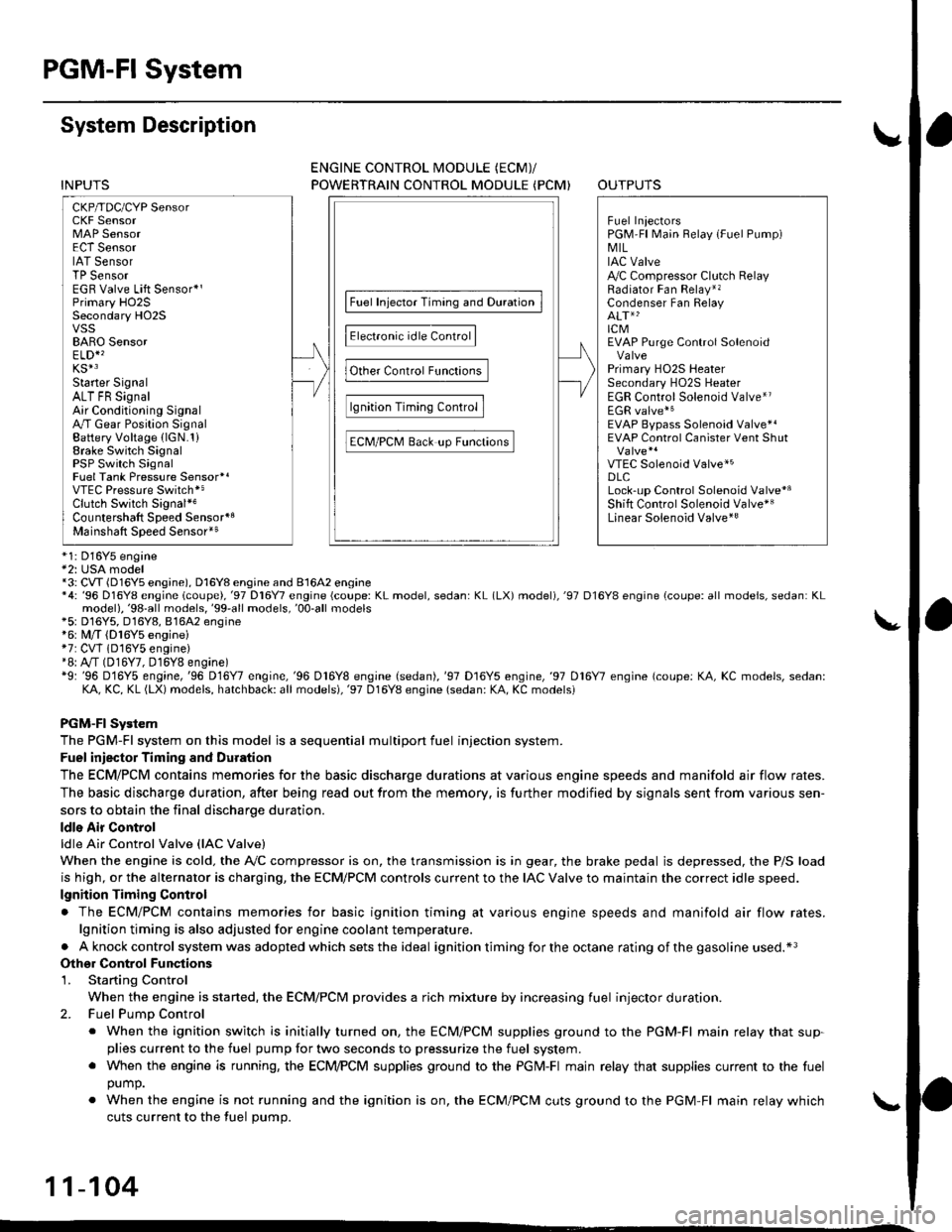
System Description
CKP/TDC/CYP Sensor
MAP Sensor
IAT SensorTP SensorEGR Valve Lift Sensor*'Primary H02SSecondary HO2SVSSBARO SensorELD*'KS€Starter SignalALT FR SignalAir Conditioning SignalA/T Gear Position SignalBattery Voltage {lGN.1}Erake Switch SignalPSP Switch SignalFuel Tank Pressure Sensor*iVTEC Pressure Switch*5Clutch Switch Signal*6Countershaft Speed SensornBMainshaft Speed Sensorrs
-\
----t /
F;ilrr j"-----fi-tri-'r.;l
Fb"t."'i" d" c;;il
F,h"'c;;tr*".io";-l
@."r.l"sc;;ll
EaM/PcM B""k-p F"""till
r\
-:/
Fuel IniectorsPGM-Fl Main Belay {Fuel Pump)MILIAC Valve!y'C Compressor Clutch RelayRadiator Fan Relay*,Condenser Fan RelayALT*'lcMEVAP Purge Control Solenoid
Primary HO2S HeaterSecondary H02S HeaterEGR Control Solenoid Valve*rEGR valve*6EVAP Bypass Solenoid Valve*'EVAP Control Canister Vent Shut
VTEC Solenoid Valve*5DLCLock-up Control Solenoid Valve*aShift Control Solenoid Valve*3Linear Solenoid Valve*3
*1: Dl6Y5 engine*2: USA model*3: CW (D16Y5 ensine), D16Y8 engine and 81642 ensine*4: '96 D16Y8 engine lcoupe),'97 Dl6Y7 engine (coupe: KL model, sedan: KL (LX) model),'97 D16Y8 engine {coupe: all models, sedan: KLmodel),'98-all models,'99'all models,'00-all models+5: D16Y5, D16Y8,816A2 engine*6: M/T (D16Y5 enginei*7: CVT 1D'l6Y5 engine)+8: A/T (D16Y7, D16Y8 engine)*9: '96 D16Y5 engine,'96 D16Y7 engine,'96 Dl6Y8 engine (sedan),'97 D16Y5 engine,'97 Dl6Y7 engine (coupe: KA, KC models, sedan:KA, KC, KL (LX) models, hatchback: all models),'97 D16Y8 engine (sedan: KA, KC modelsi
PGM-FI Sy3lem
The PGM-Fl system on this model is a sequential multipon fuel injection system.
Fuel iniector Timing and Duration
The ECM/PCM contains memories for the basic discharge durations at various engine speeds and manifold air flow rates.
The basic discharge duration, after being read out from the memory. is further modified by signals sent from various sen-
sors to obtain the final discharge duration.
ldle Air Control
ldle Air Control Valve llAC Valve)
When the engine is cold. the A,/C compressor is on, the transmission is in gear, the brake pedal is depressed, the P/S load
is high, or the alternator is charging, the ECM/PCM controls current to the IAC Valve to maintain the correct idle speed.
lgnition Timing Control
. The ECM/PCM contains memories for basic ignition timing at various engine speeds and manifold air flow rates.
lgnition timing is also adjusted for engine coolant temperature.
. Aknockcontrol system was adopted which sets the ideal ignition timing for the octane rating ofthegasoline used.*3
Othgr Control Funqtions
1. Starting Control
When the engine is started, the ECM/PCM provides a rich mixture by increasing fuel injector duration.
2. Fuel Pump Control
. When the ignition switch is initially turned on, the ECM/PCM supplies ground to the PGM-Fl main relay that sup-plies current to the fuel pump for two seconds to pressurize the fuel system.. When the engine is running, the ECI\4PCM supplies ground to the PGM-FI majn relay that supplies current to the fuel
oumo.
. When the engine is not running and the ignition is on, the ECM/PCM cuts ground to the PGM-FI main relay which
cuts current to the fuel pump.
11-104
INPUTS
ENGINE CONTROL MODULE (ECMY
POWERTRAIN CONTROL MODULE (PCM) OUTPUTS
Page 374 of 2189
3.
5.
6.
1.
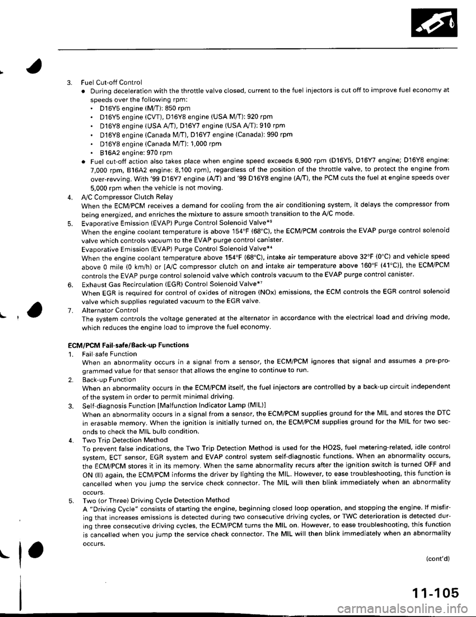
Fuel Cut-off Control
. During deceleration with the throttle valve closed, current to the fuel injectors is cut off to improve fuel economy at
speeds over the following rpm:. D16Y5 engine (M/T):850 rpm. D]6Y5 engine (CVT), D'16Y8 engine (USA M/T): 920 rpm
. Dl6Y8 engine (USA A,/I), D16Y7 engine (USA A,/T);910 rpm
. D16Y8 engine (Canada M/T), D16Y7 engine (canada): 990 rpm
' D16Y8 engine (Canada M/T): 1,000 rpm
. 816A2 engine: 970 rpm
. Fuel cut-off action also takes place when engine speed exceeds 6,900 rpm (D16Y5, D16Y7 engine; D'16Y8 engine:
7,000 rpm. 816A2 engine: 8.100 rpm), regardless of the position of the throttle valve, to protect the engine from
over-rewing. With '99 Dl6Y7 engine (A,/T) and '99 D16Y8 engine (A./T), the PCM cuts the fuel at engine speeds over
5,000 rpm when the vehicle is not moving.
IVC Compressor Clutch Relay
When the ECM/PCM receives a demand for cooling from the air conditioning system, it delays the compressor from
being energized, and enriches the mixture to assure smooth transition to the A,/C mode
Evaporative Emission (EVAP) Purge Control Solenoid Valve*'
When the engine coolant temperature is above 154'F (68'C). the ECM/PCM controls the EVAP purge control solenoid
valve which controls vacuum to the EVAP purge control canister.
Evaporative Emission (EVAP) Purge Control Solenoid Valve*a
When the engine coolant temperature above 154"F (68"C), intake air temperature above 32"F (0'C) and vehicle speed
above 0 mile (0 km/h) or [Ay'C compressor clutch on and intake air temperature above 160"F (41'C)], the ECM/PCM
controls the EVAP purge control solenoid valve which controls vacuum to the EVAP purge control canister.
Exhaust Gas Recirculation (EGR) Control Solenoid Valve*?
When EGR is required for control of oxides of nitrogen (NOx) emissions. the ECM controls the EGR control solenoid
valve which supplies regulated vacuum to the EGR valve
Alternator Control
The system controls the voltage generated at the alternator in accordance with the electrical load and driving mode,
which reduces the engine load to improve the fuel economy.
ECM/PCM Fail-safe/Back-up Functions
1. Fail safe Function
When an abnormality occurs in a signal from a sensor, the ECM/PCM ignores that signal and assumes a pre-pro-
grammed value for that sensor that allows the engine to continue to run.
2. Back-uD Function
When an abnormality occurs in the ECM/PCM itself, the fuel injectors are controlled by a back-up circuit independent
of the system in order to permit minimal driving.
3. Self diagnosis Function lMalfunction Indicator Lamp (MlL)l
When an abnormality occurs in a signal from a sensor, the ECM/PCM supplies ground for the lvllL and stores the DTC
in erasable memory. When the ignition is initially turned on, the ECM/PCM supplies ground for the MIL for two sec-
onds to check the MIL bulb condition.
4. Two Trip Detection Method
To prevent false indications, the Two Trip Detection Method is used for the HO2S, fuel metering-related. idle control
system, ECT sensor, EGR system and EVAP control system self-diagnostic functions. When an abnormality occurs,
the ECM/PCM stores it in its memory. When the same abnormality recurs after the ignition switch is turned OFF and
ON 0l) again, the ECM/PCM informs the driver by lighting the MlL. However, to ease troubleshooting, this function is
cancelled when you jump the service check connector. The MIL will then blink immediately when an abnormality
occurs,
5. Two (or Three) Driving Cycle Detection Method
A "Driving Cycle" consists ot starting the engine. beginning closed loop operation, and stopping the engine. lf misfir-
ing that increases emissions is detected during two consecutive driving cycles, or TWC deterioration is detected dur-
ing three consecutive driving cycles, the ECM/PCM turns the MIL on. However, to ease troubleshooting, this function
is cancelled when you jump the service check connector. The MIL will then blink immediately when an abnormality
occurs.
(cont'd)
1 1-1 05
.1.
Page 512 of 2189
Intake Air System
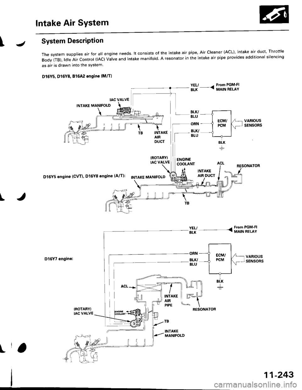
\JSystem DescriPtion
The system supp|ies air for a|| engine needs' |t consists of the intake air pipe' Air C|eaner (ACL}, intake air duct, Thrott|e
Body (TB), ldle Air control (lAc) valve and intake manifold. A resonator in the intake air pipe provides additional silencing
as air is drawn into the system.
D16Y5, D16Y8, 816A2 engine {M/Tl
YEL/ - From PGM-FIaLK - MA|N RELAY
BLK/BLU
-- ORN
INTAKEAIRDUCT
IROTARYIIAC VALVE
Iaru
ENGINECOOLANT
BLK/
INTAKEAIR DUCT
I
D16Y5 engine (CVT), D16Y8 engine (A/T)' f'ttlxr ,tla"tpoto
D16Y7 engine:
{ROTARY)IAC VALVE
VARIOUSSENSORS
INTAKEAIRPIPE
tr
RESONATOR
!r,
IAC VALVE
BLK
11-243
Page 536 of 2189
1\
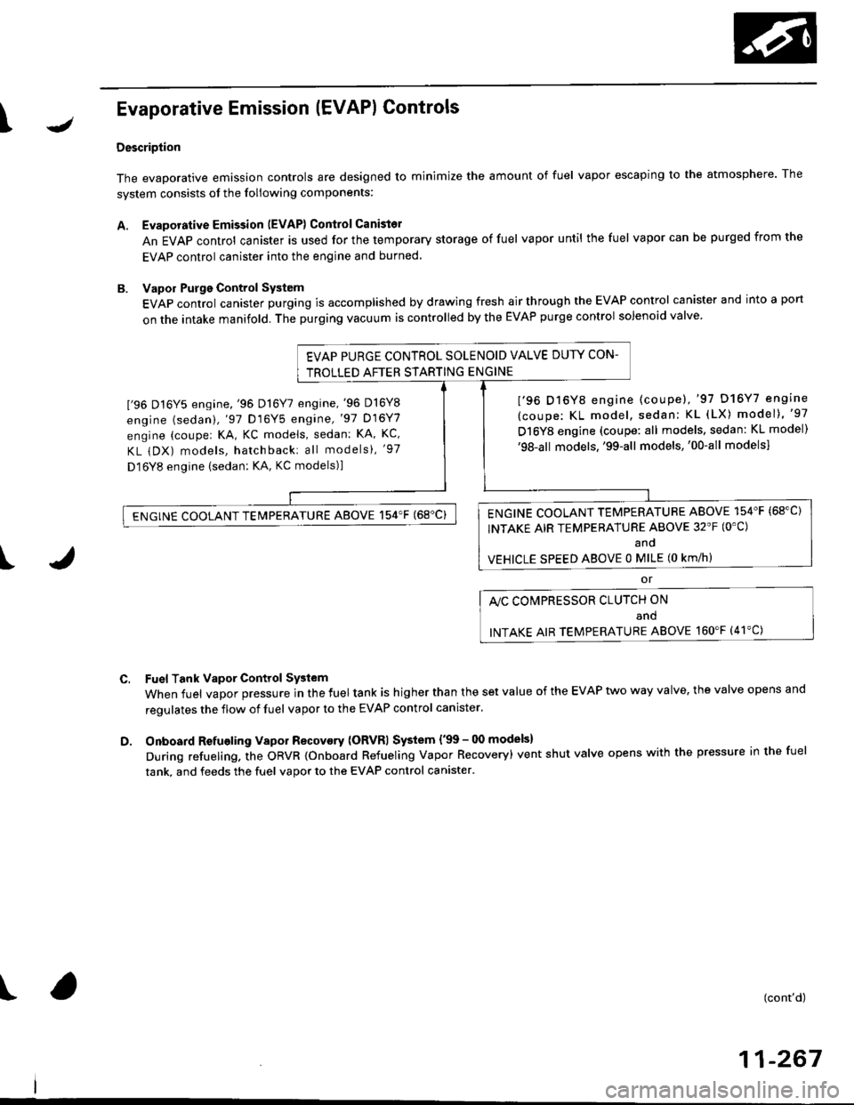
Evaporative Emission (EVAPI Controls
Description
The evaporative emission controls are designed to minimize the amount of fuel vapor escaping to the atmosphere. The
system consists of the foliowing components:
A. Evaporative Emission (EVAP) Control Canisto]
An EVAP control canister is used for the temporary storage of fuel vapor until the fuel vapor can be purged from the
EVAP control canister into the engine and burned.
B. Vapor Purge Control System
EVAP control canister purging is accomplished by drawing fresh air through the EVAP control canister and into a port
on the intake manifold. The purging vacuum is controlled by the EVAP purge control solenoid valve.
I'96 D16Y5 engine,'96 Dl6Y7 engine,'96 D16Y8
engine (sedan),'97 D16Y5 engine,'97 D16Y7
engine (couper KA, KC models, sedan: KA, Kc'
KL iDX) models, hatchback: all models), '97
D 16Y8 engine (sedan: KA, KC models)l
I'96 D16Y8 engine (coupe),'97 D16Y7 engine
(coupe: KL model, sedan: KL (LX) model)"97
D16Y8 engine (coupe: all models, sedan: KL model)'98-all models,'99-all models,'00-all modelsl
I
c.
D.
or
l'lc COMPRESSOR CLUTCH ON
and
INTAKE AIR TEMPERATURE ABOVE 160"F (41'C)
Fuel Tank Vapor Control System
When fuel vapor pressure in the fuel tank is higher than the set value of the EVAP two way valve, the valve opens and
regulates the flow of fuel vapor to the EVAP control canister.
Onboard Refueling Vapor Recovery (ORVRI System {'99 - 00 models}
During refueling. the oRVR {onboard Refueling Vapor Recovery) vent shut valve opens with the pressure in the fuel
tank. and feeds the fuel vapor to the EVAP control canister.
t(cont'd)
11-267
EVAP PURGE CONTROL SOLENOID VALVE DUTY CON-
TROLLED AFTER STARTING ENGINE
ENGINE COOLANT TEMPERATURE ABOVE 154'F {68"C)
INTAKE AIR TEMPERATURE ABOVE 32'F (O'C)
and
VEHICLE SPEED ABOVE O MILE (O KM/h}
ENGINE COOLANT TEMPERATURE ABOVE 154'F (68'C)
Page 1490 of 2189
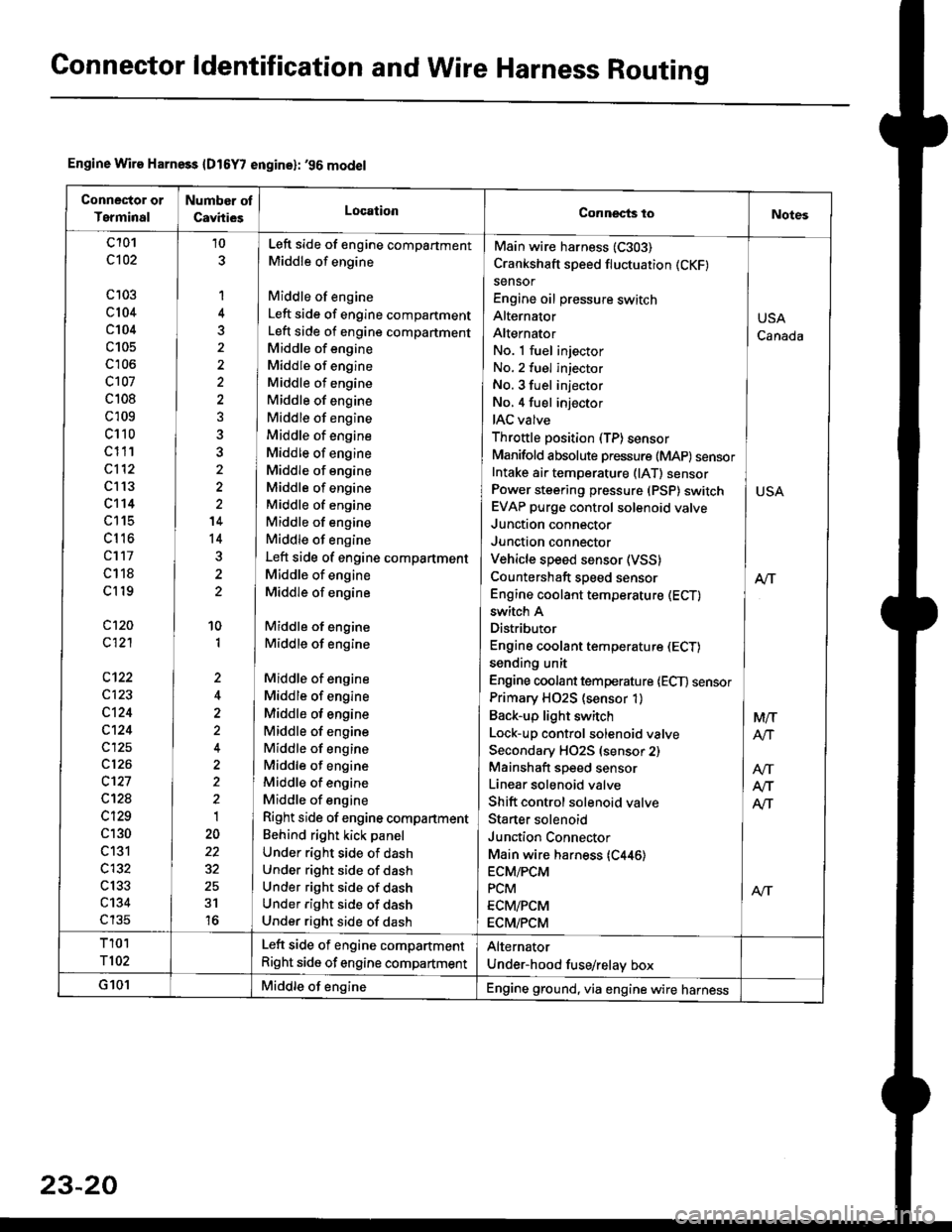
Gonnector ldentification and Wire Harness Routing
Engine Wire Harness {D16Y7 engine}: '96 model
Conneclor or
Terminal
Number ot
CavhiesLocationConnects toNotes
c101
c102
c 103
c104
c104
c105
c'r06
c107
c 108
c 109
c110
c111
c112
c l13
c't14
LttS
cl16
cl17
c118
cl19
c120
c121
c123
c124
c124
c125
c126
c't27
c12a
c129
c130
c131
c132
c133
c134
c135
10
1
4
5
'14
14
10
1
,,
2
2
1
22
31
16
No. 1 fuel injector INo. 2 fuel injector
No. 3 fuel injector INo,4 fuel injector
IAC valve l
Throttle position (TP)sensor IManifold absolute pressure (MAP) sensorIntake ai. temperature (lAT) sensor ]Power steering pressure (PSP) switch I USAEVAP purge control solenoid valve IJunction connector
Junction connector IVehicle speed sensor (VSS) |Countershaft speed sensor AlTEngine coolant temperature (ECT) I
Main wire harness (C303)
Crankshaft speed fluctuation (CKF)
sensor
Engine oil pressure switch
Alternator
Alternator
switch A
Distributor
Engine coolant temperature (ECT)
sending unit
Engine coolant temperature lECT) sensor
Primary H02S (sensor 1)
Back-up light switch
Lock-up control solenoid valve
Secondary HO2S (sensor 2)
Mainshaft speed sensor
Linear solenoid valve
Shift control solenoid valve
Staner solenoid
Junction Connector
Main wire harness {C446)ECM/PCM
PCM
ECM/PCM
ECM/PCM
Left side of engine compartment
Middle of engine
Middle of engine
Left side of engine compartment
Left side of engine compartment
Middle of engine
Middle of engine
Middle of engine
Middle of engine
Middle of engine
Middle of engine
Middle of engine
Middle of engine
Middle of engine
Middle of engine
Middle of engine
Middle of engine
Left side of engine compartment
Middle of engine
Middle of engine
Middle of engine
Middle of engine
Middle of engine
Middle of engine
Middle of engine
Middle of engine
Middle of engine
Middle of engine
Middle of engine
Middle of engine
Right side of engine compartment
Behind right kick panel
Under right side of dash
Under right side of dash
Under right side of dash
Under right side of dash
Under right side of dash
USA
Canada
M/T
AtJ
Afi
T101
T102
Left side of engine compartment
Right side of engine compartment
Alternator
Under-hood fuse/relay box
G101Middle of engineEngine ground, via engine wire harness
23-20
Page 1840 of 2189

Ground-to-Components I ndex
f.,lONOTE: All ground wires are BLK unless otherwise noted.
GroundPageComponents or Circuit Grounded
Battery (BLKYEL)
Steering pump bracket
t+-rg ITransmission housing
l
G101
(-1)
G101
(-2)
14-2
and
14-3
ano
14-1
Powertrain or engine control module (PG1 and pG2 are BLK: LG1 and LG2 are
BRN/BLK), EGR control solenoid valve (CW, EGR valve and lift sensor (Dt6yS enginewith M,/T), Engine coolant temperature switch, pGM-Fl main relay, power steeringpressure switch (USA), Primary HO2S (D16Y5 engine with l\/,/T), Vehicle speed sensor,VTEC pressure switch (D16Y5/D16Y8 engines), CKF sensor (BRN/BLK), Transmission
control module (CYf) (Pc1 is BLK: LG1 is BRN/BLK)
Shielding betvveen the PCM or ECM and these components (all have BRN/BLK wires):
CKF sensor, TDC/CKP/CYP sensor. Primary and secondary heated oxygen sensors.
Knock sensor (CWDl6YB engine), Mainshaft speed sensor (AiT except CVT),
I Countershaft speed sensor (A/T except CVf)
Shielding between the TCM and these components (CVT) (all have BRN/BLK wires):
Drive pulley speed sensor, Driven pulley speed sensor, Secondary gear shaft
speed sensor
Powertrain or engine control module (PG1 and pG2 are BLK; LG1 and LGz are
BRN/BLK), EGR control solenoid valve (D16Y5 engine), EGR valve (Dt685), Engine
coolant temperature switch, Fuel pressure regulator shut-off solenoid valve (D1685),
PGM-FI main relay, Power steering pressure switch (USA), Vehicle speed sensor, VTECpressure switch (All except D16Y7 engine), CKF sensor (A
except 81642) (BRN/BLK)
Shielding between the PCM or ECM and these components (all have BRN/BLK wires):
CKF sensor, TDC/CKP/CYP sensor, Primary and secondary heated oxygen sensors,
Knock sensor (All except D16Y7 engine), i/ainshaft speed sensor (Arf except CW),
Countershaft speed sensor (A,/T except CVf), Drive pulley speed sensor (CW), Drivenpulley speed sensor (CVT), Secondary gear shaft speed sensor (CVf)
I Badiator fan motor, Right front parking/turn signat tight, Right headtight
G20214-4I Cruise control actuator, Left front parking/turn signal lights, Left headlight, Rear window
I washer motor, Windshield washer motor, Washer fluid level switch (,99-'00 Canada)
G401| +-o
and
14-7
Accessory power socket, Brake fluid level switch, Clutch interlock switch (M/T), Clutchswitch (lillT with cruise/D16Y5 engine with MfD, Combination wiper switch (Z wires),
Cruise control main switch, Cruise control unit, Dash lights brightness controller, Data
link connector, Daytime running lights control unit (Canada), Gauge assembly, Horn('96-'97 models), Integrated control unit, Interlock control unit (ArI), Keyless door lock
control unit ('99-'00 models with keyless), Moonroof close and open relays, Moonroof
switch, Park pin switch (A/r), Power window relay, Rear window defogger relay, Rear
window defogger switch ('96-'98 models), Steering lock, Stereo radio tuner (,96-,98
USA: LX, EX, and HX), Turn signal/hazard relay, Windshield wiper motor.....plus
everything grounded through G402
6-6
Page 2137 of 2189
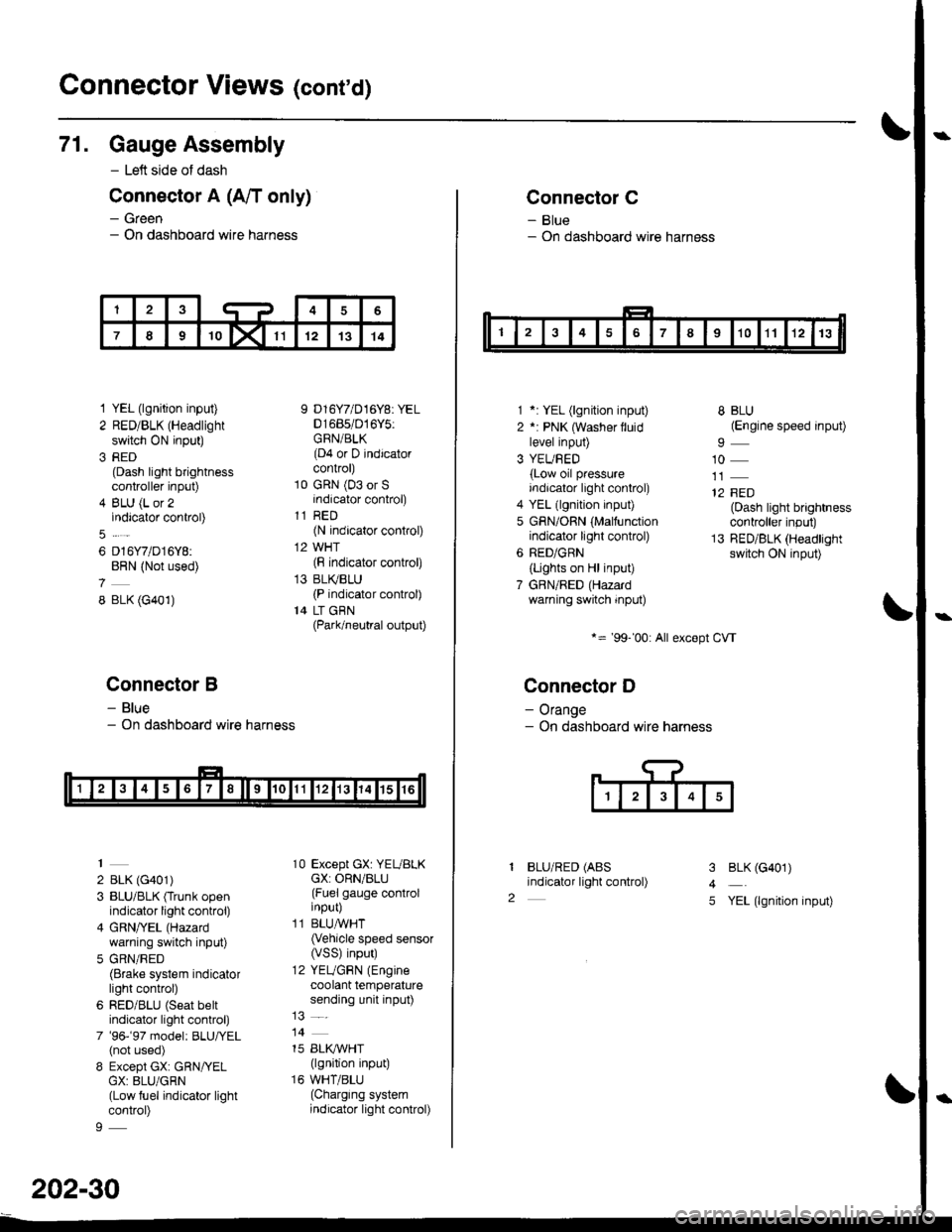
Connector Views (conrd)
71. Gauge Assembly
- Left side of dash
Connector A (A/T only)
- Green- On dashboard wire harness
1 YEL (lgnition input)
2 RED/BLK (Headlight
switch ON input)
3 RED(Dash light brightnesscontroller input)
4 BLU (L or 2indicator control)
6 D16Y7/D16Y8:BRN (Not used)
8 BLK (G401)
Connector B
- Blue- On dashboard wire harness
2 BLK (G401)
3 BLU/BLK (Trunk openindicator light control)
4 GRN/YEL (Hazard
warning switch input)
5 GRN/RED(Brake system indicatorlight control)
6 RED/BLU (Seat beltindicator light control)
7 '96-'97 model: BLU,ryEL(not used)
8 Except GX: GRN/YELGX: 8LU/GRN(Low fuel indicator lightcontrol)
9 D16Y7/D16Y8: YEL01685/016Y5:GRN/BLK(D4 or D indicatorcontrol)
10 GRN (03 or Sindicator control)
11 RED(N indicator control)
12 WHT(F indicator control)
13 BLI(BLU(P indicator control)
14 LT GBN(Park/neutral output)
10 Except GX: YEUBLKcX: ORN/BLU(Fuel gauge controlinput)
11 BLUAVHT(Vehicle speed sensor(VSS) input)
12 YEUGRN (Engine
coolant temperaturesending unit input)
14
15 BLI(IVHT(lgnition input)
16 WHT/BLU(Charging systemindicator light control)
202-30
Connector C
- Blue- On dashboard wire harness
1 *: YEL (lgnition input)
2 *: PNK (Washer lluidlevel input)
3 YEUBED(Low oil pressureindicator light control)
4 YEL (lgnition input)
5 GRN/ORN (Malfunctionindicator light control)
6 RED/GRN
{Lights on Hl input)
7 GBN/RED (Hazardwarning switch input)
*= '99-'00: All except CVT
Connector D
- Orange- On dashboard wire harness
BLU/RED (ABS
indicator light control)
8 BLU(Engine speed input)
10
12 FED(Dash light brightnesscontroller input)
13 RED/BLK (Headlightswitch ON input)
I
2
3
4
5
BLK (G401)
YEL (lgnition input)