circuit HONDA CIVIC 1998 6.G Workshop Manual
[x] Cancel search | Manufacturer: HONDA, Model Year: 1998, Model line: CIVIC, Model: HONDA CIVIC 1998 6.GPages: 2189, PDF Size: 69.39 MB
Page 1724 of 2189
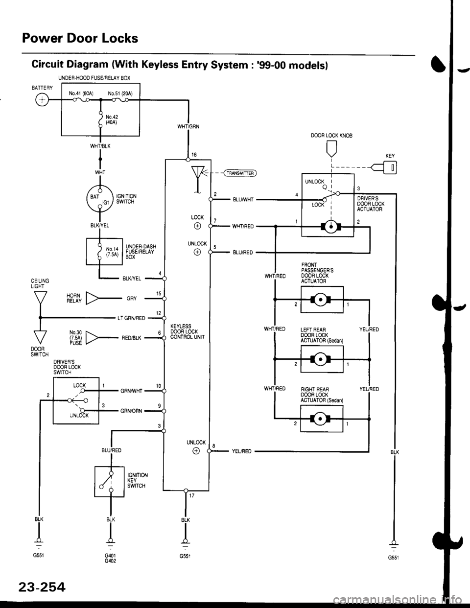
Power Door Locks
Circuit Diagram (With Keyless Entry System : '99-00 models)
BL(
I
G551
UNDEF.HOOO FUSE/RELAY BOX
N0.41 1804) N0.51 (20 )
KEYLESSDOOF LOCKCOIJTROL UNIT
DRIVEF'SDOOF LOCKSWITCH
23-254
Page 1725 of 2189
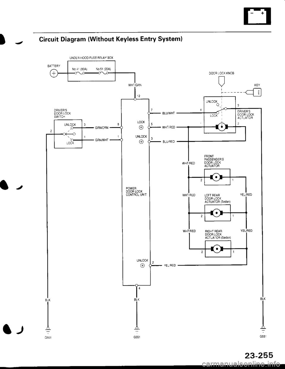
UNDER HOOD FUSE/RELAY BOX
)1Circuit Diagram (Without Keyless Entry System)
Ir
l -,t
l'8LK
G551
23-255
ORIVER'SDOOR LOCKSW TCH
BLK
G55l
POWERDOOR LOCKCONTROT UN T
Page 1732 of 2189
Power Door Locks
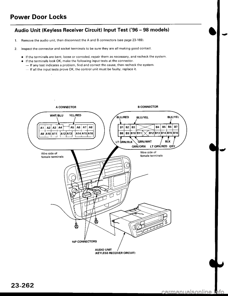
Audio Unit {Keyless Receiver Circuitl Input Test ('96 - 98 models}
Remove the audio unit, then disconnect the A and B connectors (see page 23-189).
Inspect the connector and socket terminals to be sure they are all making good contact
. lf the terminals are bent, loose or corroded, repair them as necessary, and recheck the system
. lf the terminals look OK, make the following input tests at the connector.
- lf anv test indicates a problem, find and correct the cause, then recheck the system
lf all the inout tests prove OK, the control unit must be faulty; replace it.
A CONNECTOBB CONNECTOR
16P CONNECTORS
AUDIO UNIT
L
2.
WHT/BLU YEL/RED
{KEYLESS RECEIVER CIRCUIT}
23-262
Page 1734 of 2189
Power Door Locks
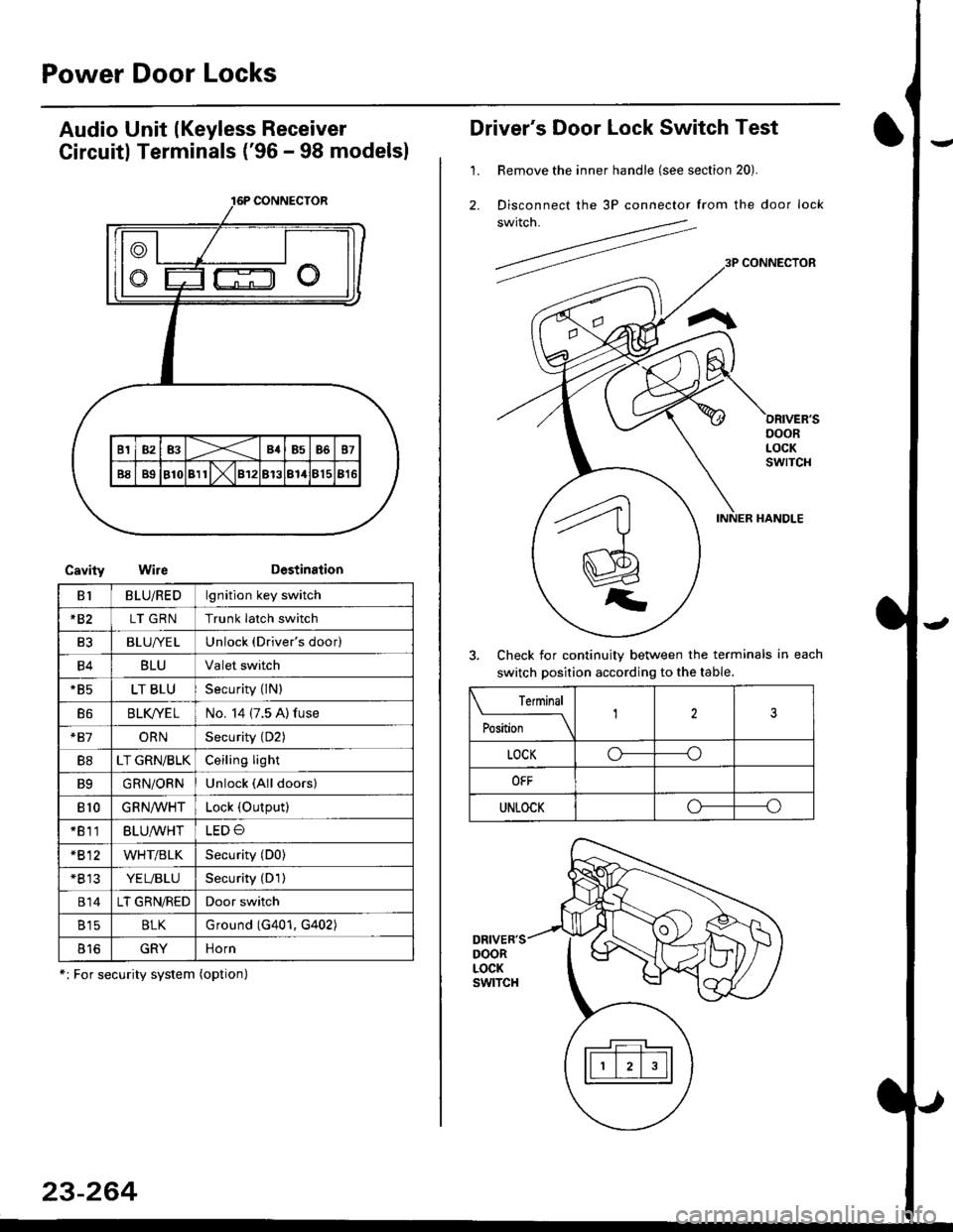
Audio Unit lKeyless Receiver
Circuitl Terminals ('96 - 98 modelsl
CavityWireDestination
16P CONNECTOR
B1BLU/REDlgnition key switch
*82LT GRNTrunk latch switch
Ft2BLU/YELUnlock (Driver's door)
B4BLUValet switch
*85LT BLUSecurity {lN)
B6BLK/YE LNo. 14 (7.5 A) fuse
*81ORNSecurity (D2)
B8LT GRN/BLKCeiling light
B9GRN/ORNUnlock (All doors)
810GRNA/VHTLock (OutPutl
*811BLU/WHTLED O
*812WHT/BLKSecurity (D0)
+B 13YEL/BLUSecurity (D'l )
814LT GRN/REDDoor switch
B15BLKG round (G401, G402)
o toGRYnorn
*: For security system (option)
23-264
Driver's Door Lock Switch Test
1. Remove the inner handle (see section 20).
2. Disconnect the 3P connector from the door lock
switch.
Check for continuity between the terminals in each
switch position according to the table.
DRIVER'SDOORLOCKswtTcH
Terminal
Position123
LOCKo-----o
OFF
UNLOCKo----o
Page 1739 of 2189
)
Troubleshooting
Sef f -dia gnostic Proctdurcs ............. 2+13
Reading the DTC .............................. 2+13
Erasing the DTC Mcnrory ................ 24-15
Troubleshooting h.ttnitt.nt
Failures ..............24-15
SRS U n it ldcntificrtion .................... 24- 1 6
Diagnostic Troublc Code (DTC)
Chart - '96 - 97 Models..."'."....... 24-17
Diagnostic Trouble Code (DTCI
Chart - '$ - 00 Models '.........""' 24'19
SRS lndicaror Light Wire
connections ...'.,24-25
Ff owcharts ........,,,,.24-26
Airbag
Repfacemant ...'.'...24-67
Disposaf .................24'70
Cable Reel
Repfacement .........24'72
SRS Unh
Repfacement ..'......24'76
l-l
-+
sRs
Supplemental Restraint System (SRSI
Speciaf Tools ... ...........24'2
Component/Wirin g Locations
fndex ................ ......24-3
Description ................ 24-5
Circuit Diagram ......." 24'6
Precautions/Procedures
Generaf Precautions ...............,,,,,,,.. 24-7
Airbag Handling and Storage .........24-7
SRS Unit Precautions ...................... 24-8
Inspection After Deployment ........' 24-8
Wiring Precautions ................... ....... 24'9
Backprobing Spring-loaded Lock
Connectors .......,24-9
Spring-loaded Lock Connectol ....,,. 24-10
Spring-loaded Lock Connector with
Built-in Short Contact ................. 24-10
Disconnecting the Airbag
Connector(sl .....' 24'11
Steering-related Precautions ...,.,.,,. 24'12
Page 1743 of 2189
Description
)
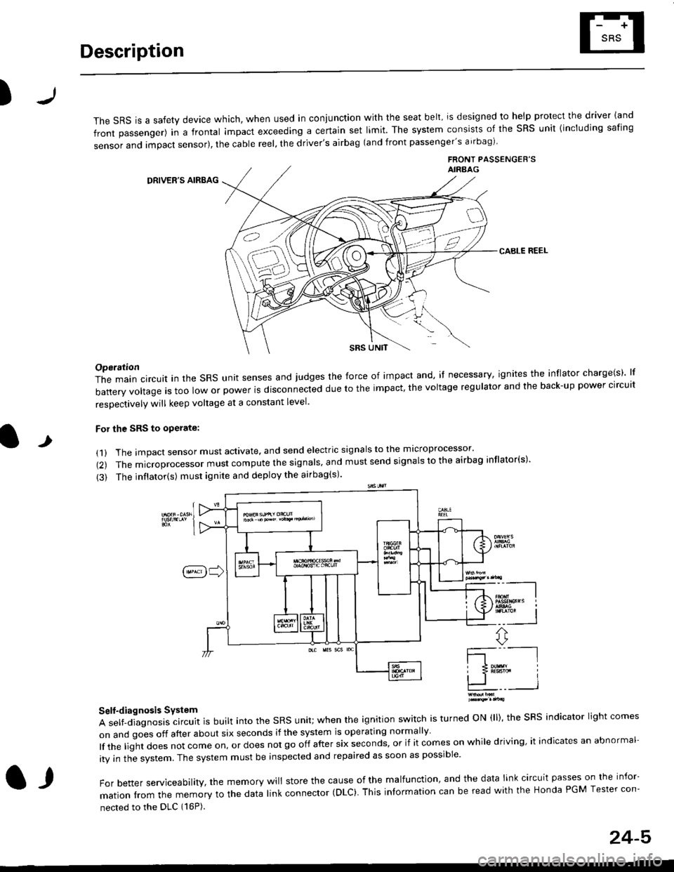
The sRS is a safety device which, when used in coniunction with the seat belt, is designed to help protect the driver land
front passenger) in a frontal impact exceeding a certain set limit. The system consists of the sRS unit {including safing
sensor and impact sensor), the cable reel, the driver's airbag (and front passenger's airbag)
FRONT PASSENGEB'SAIRAAG
DRIVER'S AIRBAG
CABLE REEL
SRS UNtT
t
Operation
The main circuit in the SRS unit senses and judges the force of impact and, if necessary, ignites the inflator charge(s) lf
battery voltage is too low or power is disconnected due to the impact, the voltage regulator and the back-up power clrcult
resoectivelv will keep voltage at a constant level.
For the SRS to operate:
(1) The impact sensor must activate. and send electric signals to the mlcroprocessor'
(2) The microprocessor must compute the signals' and must send signals to the airbag inflator(s)'
{3) The inflator(s) must ignite and deploy the airbag(s)'
_"-_-l
Ir3B!#h i
!.. I
ffi,*
Self-diagnosis System
A self-diagnosis circuit is built into the SRS unit; when the ignition switch is turned ON (ll), the SRS indicator light comes
on and goes off after about six seconds if the system is operating normally
lf the liglt does not come on, or does not go off after six seconds, or if it comes on while driving, it indicates an abnormal-
ity in the system. The system must be inspected and repaired as soon as possible
For better serviceability, the memory will store the cause of the malfunctlon, and the data link circuit passes on the infor-
mation from the memory to the data link connector (DLC). This intormation can be read with the Honda PGM Tesler con-
nected to the DLC (16P).
l,
24-5
Page 1744 of 2189
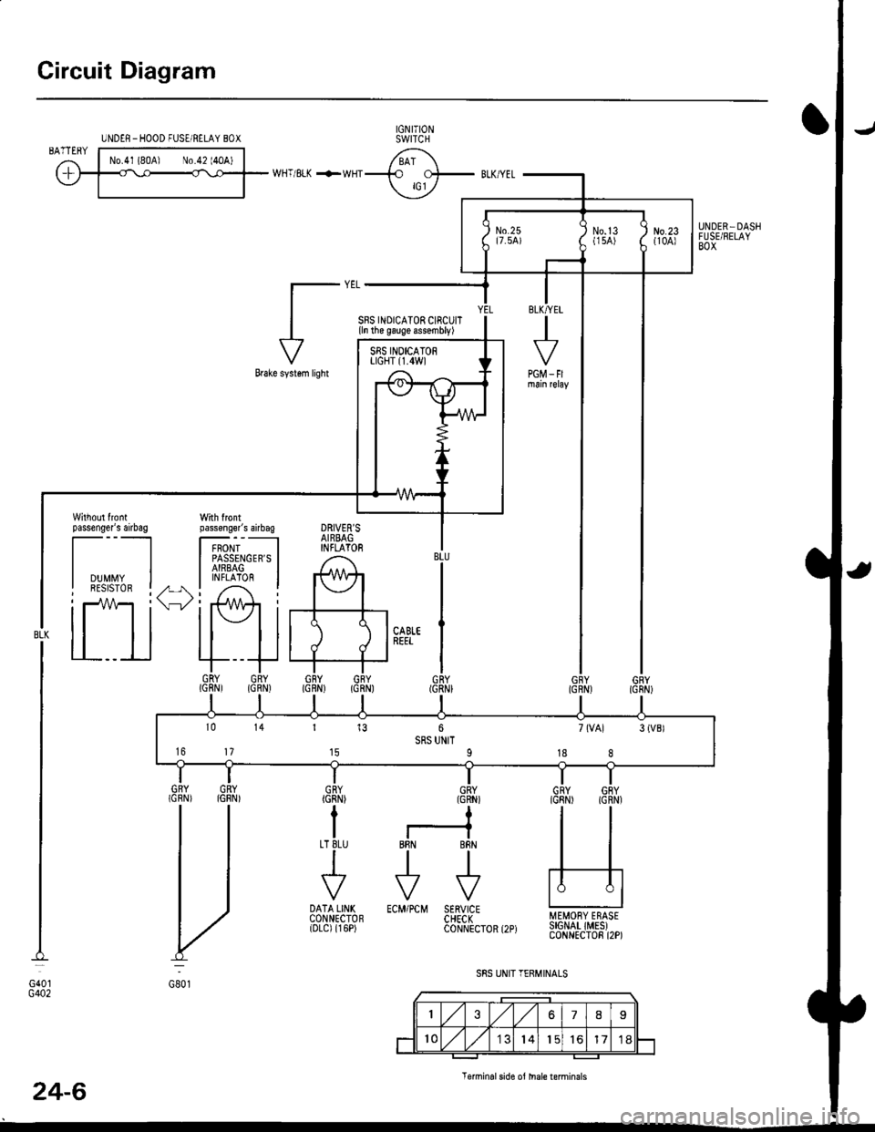
Circuit Diagram
UNDER-HOOD FUSE/RELAY 8OXIGNITIONSWITCH
WHT/8LI( +WHT
Brake systsm light
passenger's airbag
l----ltlI DUMMY II BESISTOR I
tll
tl
la rl
MEMORY ERASESIGNAT IMES)CONNECTOR I2P)
GRY{GRN)
I
BRN BRN
tl.-l- .-r-\./ \./
ECM/PCM SERVICECHECKCONNECTOR
ILT 8LU
I
t'7
DATA LINKCONNECTOR{DLC) {r6P)
GRY GRY(GRN) IGNN)
V:
G801
Teminalside oi thal€ terminals
24-6
4''
SRS UNIT TERMINALSG40tG402
SBS INDICATOR CIRCUIT{ln the gauge assembly)
PGM_FI
DRIVER'SAIRBAGINFLATOR
10 14 r 13 6 7(VAl 3{VBlSRS UNIT16 17 t5 9 18 8
Page 1745 of 2189
Precautions/ Procedures
)General Precautions
r Carefully inspect any SRS part before you install it Do
not install any part that shows signs of being dropped
or improperly handled' such as dents, cracks or defor-
mation:
- Airbags- Cable reel
- SRS unit
-
Use only a digital multimeter to check the system lf
it's not a Honda multimeter, make sure its output ls
1O mA (0.01 A) or less when switched to the smallest
value in the ohmmeter range. A tester with a higher
output could damage the airbag circuit or cause acci-
dental deployment and possible injury'
I Do not install used SRS parts from another vehicle
When making SRS repairs, use only new pans'
) Except when performing electrical inspections'
always disconnect both the negative cable and posl-
tive cable from the battery, and wait at least three
minutes before beginning work
r Replacement of the combination light and wiper/
washer switches and cruise control switch can be
done without removing the steering wheel:
- Combinalion light and wiper/washer switch replace
ment, see section 23
- Cruise control sevresume switch replacement' see
section 23.
. Whenever the ignition switch is ON {ll), or has been
turned OFF for less than three minutes' be careful not
to bump the SRS unit; the airbag(s) could accidental-
ly deploy and cause damage or injury'
. Whenever the airbag{s) has(have) been activated'
replace the SRS unit.l,
2+7
Airbag Handling and Storage
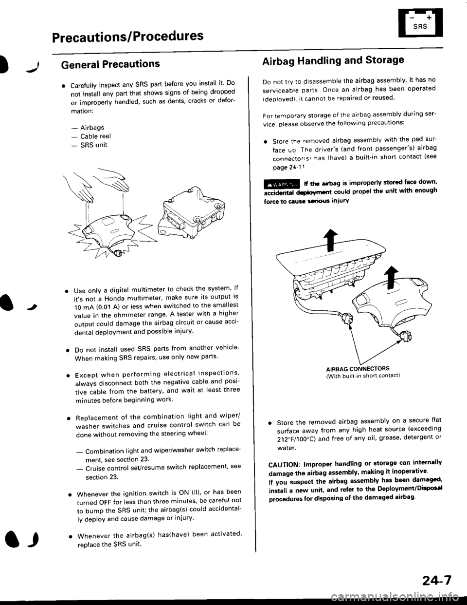
Do not try to disassemble the airbag assembly. lt has no
serviceable parts Once an airbag has been operated
(deployed). it cannot be repaired or reused'
For temporary storage of the airbag assembly during ser-
vice. olease observe the following precauttons:
. store the .emoved airbag assemblv with the pad sur-
face uo The driver's (and front passenger's) airbag
connecto''s'-as {have) a built.in short contact (see
page 2a-l 1
: | ..r r-+r-a k imninncrlv slorcd lace down,-""dd.r6t dtatltt-,tl could propel the unit whh enough
force lo c.usa 3a.ix! intury
AIRBAG CONNECTORS(With built in shon contact)
. Store the removed airbag assembly on a secure flat
surface away from any high heat source {exceeding
212"FI1OO"CJ and free of any oil' grease, detergent or
water.
CAUTION: lmproper handling or storage can intern'lJy
damage the airbag assembly, making it inoperativo
lf you suspect the airbag assembly has been dam€cd'
inslall a new unit. and relsr lo the Deployment/DisPG'l
olocedules for disposing ol the damaged airbag
Page 1751 of 2189
rl
Troubleshooting
t)
Self-diagnostic Procedures
The self-diagnostic function of the SRS system allows it to locate the causes of system problems and to store this informa' I
tion in memory. For easier troubleshooting, this data can be retrieved via a data link circuit l
. When you turn the ignition switch ON (ll), the SRS indicator will come on. ll it goes off after six seconds. the system is
norma l.
. lf there is an abnormality, the system locates and defines the problem, stores this information in memory, and turns
the sRS indicator light on. The data will remain in the memory even when the ignition switch is turned off or if the bat-
tery is disconnected.
o when you connect the scs service connector to the service check connector (2P), and turn the ignition switch oN (ll),
thesRsindicator|ightwi||indicatethediagnostictroub|ecode(DTC)bythenumberofb|inks.
. After reading and recording the DTC. proceed with the troubleshooting for this code'
Precauiions
.Useon|yadigita|mU|timetertocheckthesystem'|fit,snotaHondamu|timeter,makesureitsoutputisl0mA(0.01A)
or|esswhenSwitchedtothesma||estva|ueintheohmmeterrange,AtesterwithahigheroUtpUtcoulddamagethe��
airbag circuit or cause accidental airbag deployment and possible injury'
r when-ever the ignition switch is oN (ll). or has been turned oFF for lessthan three minutes, be careful nottobumpthe
SRS unit; the airbags could accidentally deploy and cause damage or injuries
. Before you ,"n1ou" th" SRS main harness, disconnect the driver's airbag connector (and the front passenger's airbag
connector).
. Make sure the battery is sufficiently charged {see section 23}. lf the battery is dead or low, measuring valLles won t be
correct.
. Do not touch a tester probe to the terminals in the sRS unit or harness connectors, and do not connect the terminals
with a jumper wire. Use only the backprobe set or the special tools'
For backprobing spring-loaded lock type connectors, refer to page 24-9'
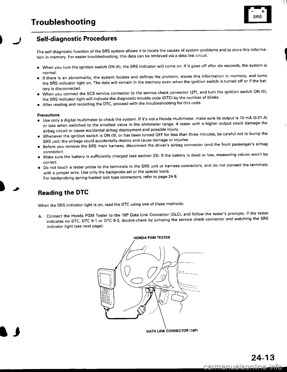
Reading the DTC
when the SRS indicator light is on, read the DTC using one of these methods:
A. Connect the Honda PGM Tester to the 16P Data Link Connector {DLC), and follow the tester's prompts lf the tester
indicatesnoDTc,DTcg-1orDTc9-2,doub|e-checkbyjumpingtheservicecheckconnectorandwatchingthesRS
indicator light (see next Page)
HONDA PGM TESTER
DATA LINK CONNECTOR Il6PI
l,
24-13
Page 1755 of 2189
l
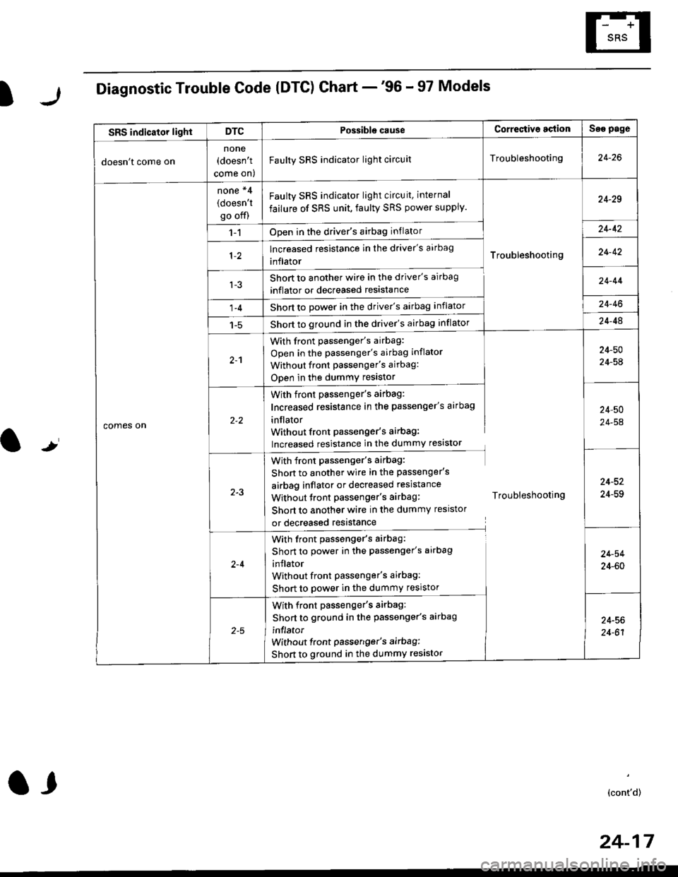
Diagnostic Trouble Code (DTG) Chart -'96 - 97 Models
t
SRS indicator lightDTCPossible causeCorrectiv6 actionSae page
doesn't come on
none(doesn't
come on)
Faulty SRS indicator light circuitTroubleshooting24-26
comes on
none *4
(doesn't
go off)
Faulty SRS indicator light circuit, internal
failure of SRS unit, faulty SRS power supply.
Troubleshooting
24-29
1-1Open in the driver's airbag inflator24-42
lncreased resistance in the driver's aarbag
inflator24-42
l-3Short to another wire in the driver's airbag
inflator or decreased resistance
Short to Dower in the driver's airbag inflator
Short to ground in the driver's airbag inflator
24-44
1-424-46
1-524-48
2-1
With front passenger's airbag:
Open in the passenger's airbag inflator
Without front Passenger's airbag:
ODen in the dummy resistor
24-50
24-54
With front passenger's airbag:
Increased resistance in the passenger's airbag
inflator
Without front Passenger's airbag:
lncreased resistance in the dummy resistor
24,50
24-54
2-3
With front passenger's airbag:
Shon to another wire in the passenger's
airbag inflator or decreased resistance
Without tront passenger's airbag: Troubleshooting
Short to another wire in the dummy resistor
or decreased resistance
24-52
24-59
2-4
With front passenger's airbag:
Short to power in the passenger's airbag
inJlator
Without front Passenger's airbag:
Short to power in the dummy resistor
24-54
24-60
With front passenger's airbag:
Short to ground in the passenger's aarbag
inflator
without front passenger's airbag:
Short to ground in the dummy resistor
24-56
24-61
(cont'd)
24-17
a,