cruise control HONDA CIVIC 1998 6.G Workshop Manual
[x] Cancel search | Manufacturer: HONDA, Model Year: 1998, Model line: CIVIC, Model: HONDA CIVIC 1998 6.GPages: 2189, PDF Size: 69.39 MB
Page 110 of 2189
Engine Removal/lnstallation
Installation (cont'd)
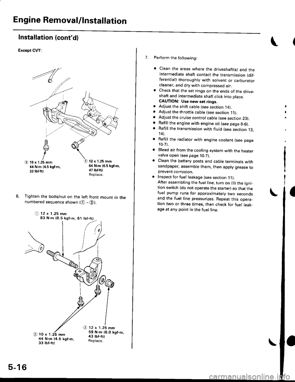
Except CVT:
12 x 1.25 mm64 N.m (6.5 kgd.m,
Tighten the bolts/nut on the left front mount in thenumbered sequence shown {O - @).
(t 12 x 1.25 mm83 N'm (8.5 kgf.m,61 tbt.trl
/+4 N.m 14.5 kgf.m,33 lbt.trl
O 12 r 1.25 mm59 N.m 16.0 kgt.m,43 tbt.rtlSeplace.
5-16
\
7. Perform the following:
. Clean the areas where the driveshaft(s) and theintermediate shaft contact the transmission (dif_ferential) thoroughly with solvent or carburetorcteaner, and dry with compressed air.. Check that the set rings on the ends of the drive_shaft and intermediate shaft click into place.CAUTION: Use new set rings,. Adjust the shift cable (see section 14).. Adjust the throttle cable (see section 11).. Adjust the cruise control cable (see section 23).. Refill the engine with engine oil (see page 8-6).. Refill the transmission with fluid (see section 13,14).
. Refill the radiator with engine coolant (see page10-7).
. Bleed air from the cooling system with the heatervalve open (see page j0-7).
. Clean the battery posts and cable terminals withsandpaper, assemble them, then apply grease toprevent corrosaon.. Inspect for fuel leakage (see section j l).After assembling the fuel line, turn on l) the igni_tion switch (do not operate the starter) so that thefuel pump runs for approximately two secondsand the fuel line pressurizes. Repeat this opera_taon two or three times, then check for fuel leak_age at any point in the fuel line,
Page 281 of 2189
System Description
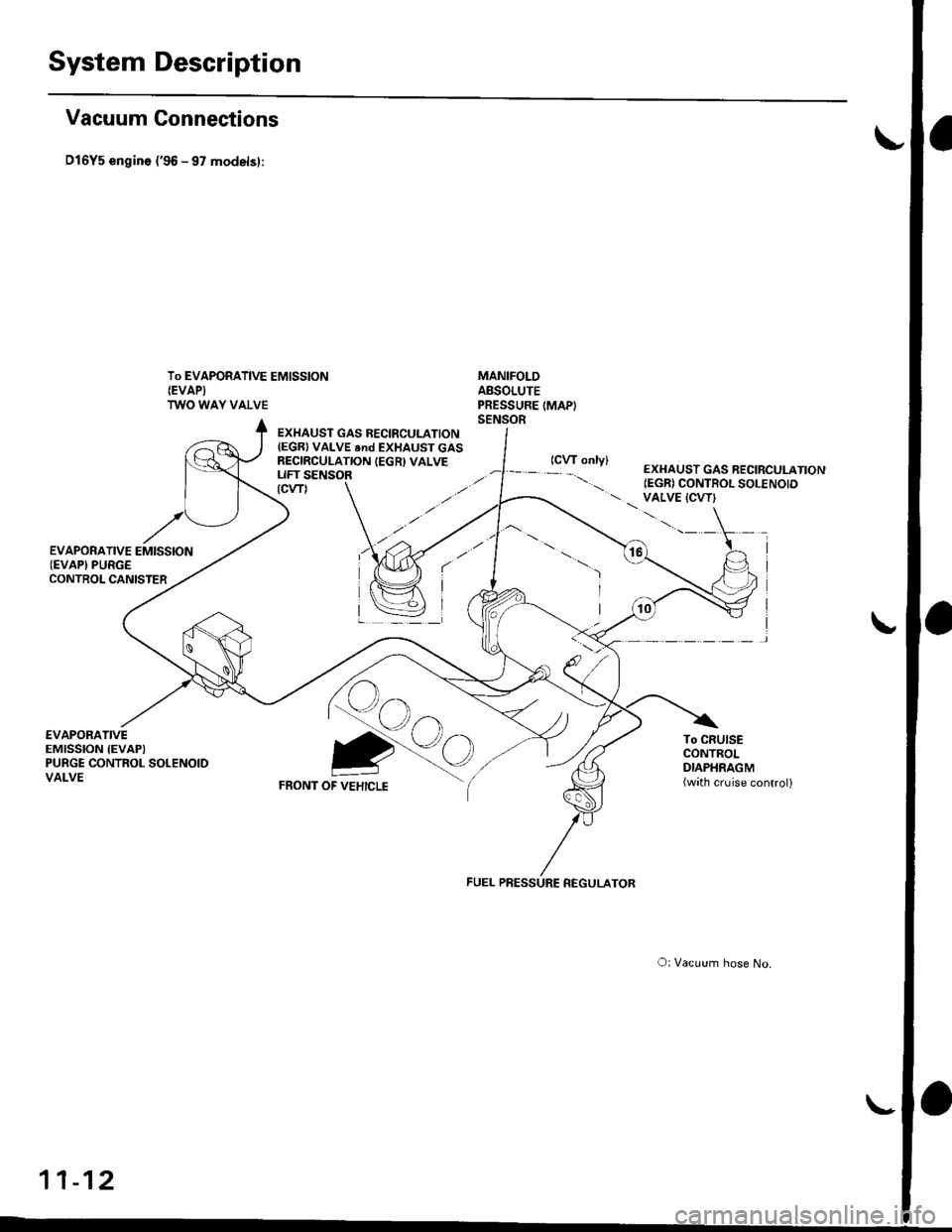
Vacuum Connections
D16Y5 engin6 ('96 - 97 modelsl:
To EVAPORATIVE EMISSION(EVAPI
TWO WAY VALVE
MANIFOLDABSOLUTEPRESSURE IMAPISENSOR
€VAPORATIVEEMISSION IEVAPIPURGE CONTROL SOLENOIDVALVE
EXHAUST GAS BECIRCULATION(EGR) VALVE end EXHAUST GASRECIRCULATION IEGR) VALVELIFT SENSOR
Qo
FRONT OF VEHICLE
To CRUISECONTROLDIAPHRAGM(wath cruise control)
Qo
O: Vacuum hose No.
11-12
EXHAUST GAS RECIRCULATION(EGR) CONTROL SOLENOID VALVE {CVT}\.'.-' \
I
I
)
FUEL PRESSURE REGULATOR
Page 282 of 2189
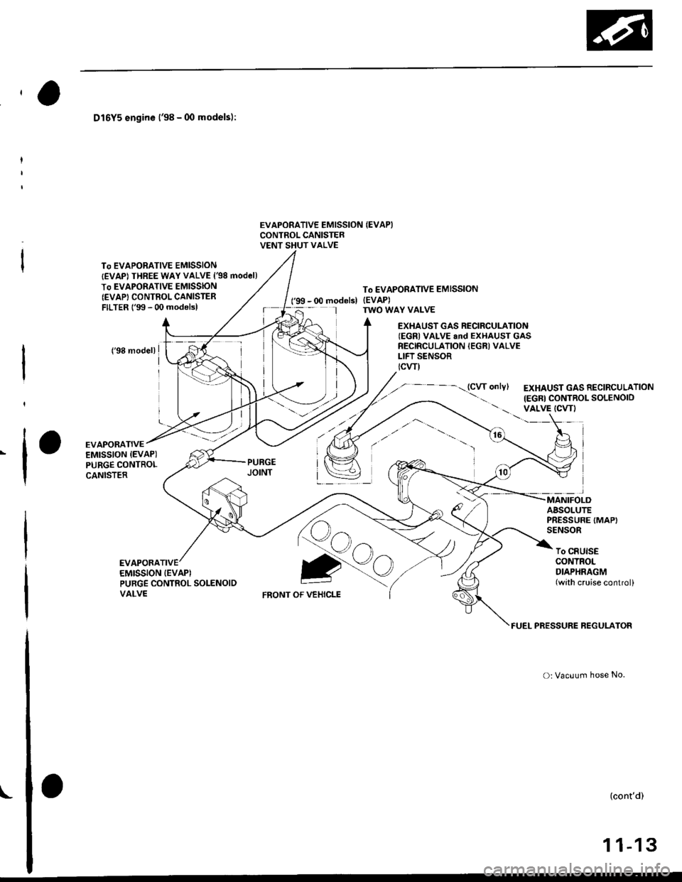
D16Y5 engine l'98 - 00 models):
To EVAPORATIVE EMISSIONtEVAPI THREE WAY VALVE {98 model)
To EVAPORATIVE EMISSIONIEVAP' CONTBOLCANISTERFILTER 1'99 - 00 modelsl
EVAPORATIVE EMISSION {EVAPICONTROL CANISTERVENT SHUT VALVE
To EVAPORATIVE EMISSION
l'99 - 00 modelsl {EVAP)TWO WAY VALVE
EXHAUST GAS RECIRCULATION(EGRI VALVE and EXHAUST GASRECIRCULATION IEGRI VALVELIFT SENSORtcwl
..,.-----.-(CWontylEXHAUST GAS RECIRCULATION
IEGR} CONTROL SOLENOIOVALVE ICVTI
,t'ffi,
ig
EVAPORATIVEEMISSION {EVAP)PURGE CONTROLCANISTER
MANIFOLDABSOLUTEPRESSURE {MAPISENSOR
EVAPORATIVEEMISSION {EVAP)Qo
To CRUISECONTROLDIAPHRAGM(with cruise control)PURGE CONTROL SOLENOIDVALVEFRONT OF VEHICLE
FUEL PRESSURE REGULATOR
o: Vacuum hose No.
(cont'd)
1 1-13
L
Page 283 of 2189
System Description
Vacuum Connections {cont'd}
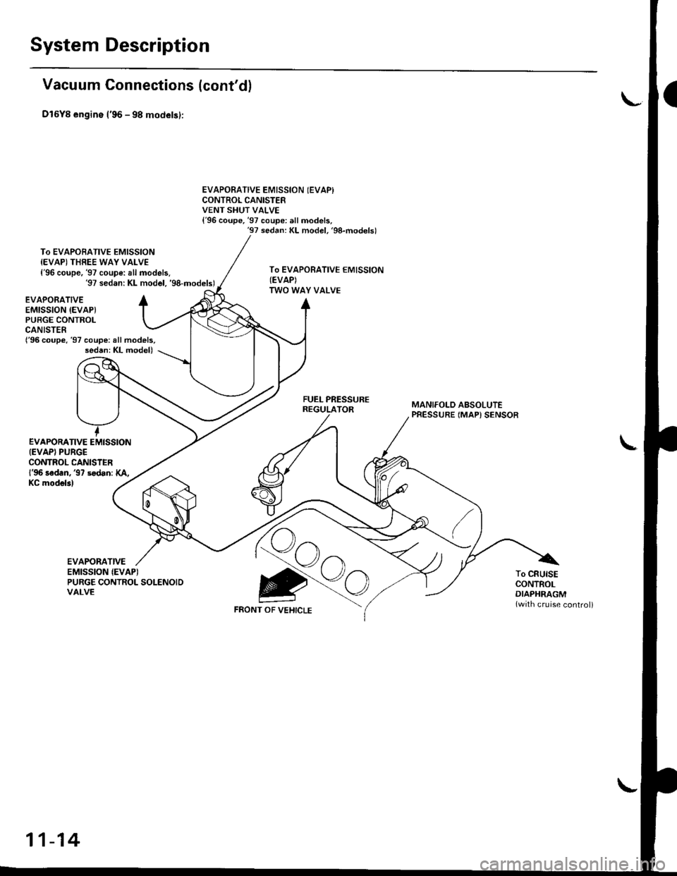
Dl6Y8 engine l'96 - 98 models):
To EVAPOBATIVE EMISSIONIEVAPI THREE WAY VALVE{'96 coupe, '97 coupe: all models.'97 sedan: KL model. 'g8-models)
EVAPORATIVE EMISSION (EVAPI
CONTROL CANISTERVENT SHUT VALVE{'96 coupe,'97 coupe: all models,'97 sedan: KL model. 'g8-modelsl
To EVAPORATIVE EMISSION{EVAP)TWO WAY VALVE
{'96 coupe,'97 coupe: all models,sed6n: KL model)
EVAPORATIVEEMISSION {EVAPIPUBGE CONTROLCANISTER
EVAPORATIVE EMISSION{EVAPI PUBGECONTROL CANISIERl'96 sadan, '97 sodan: XA,
FUEL PRESSUREREGULATORMANIFOLD ABSOLUTEPRESSURE (MAP) SENSOR
I
KC mod6l3l
EVAPORATIVEEMISSION {EVAPITo CRUISECONTROLDIAPHRAGM{with cruise control)
PURGE CONTROL SOLENOIDVALVE
FRONT OF VEHICLE
11-14
Page 284 of 2189
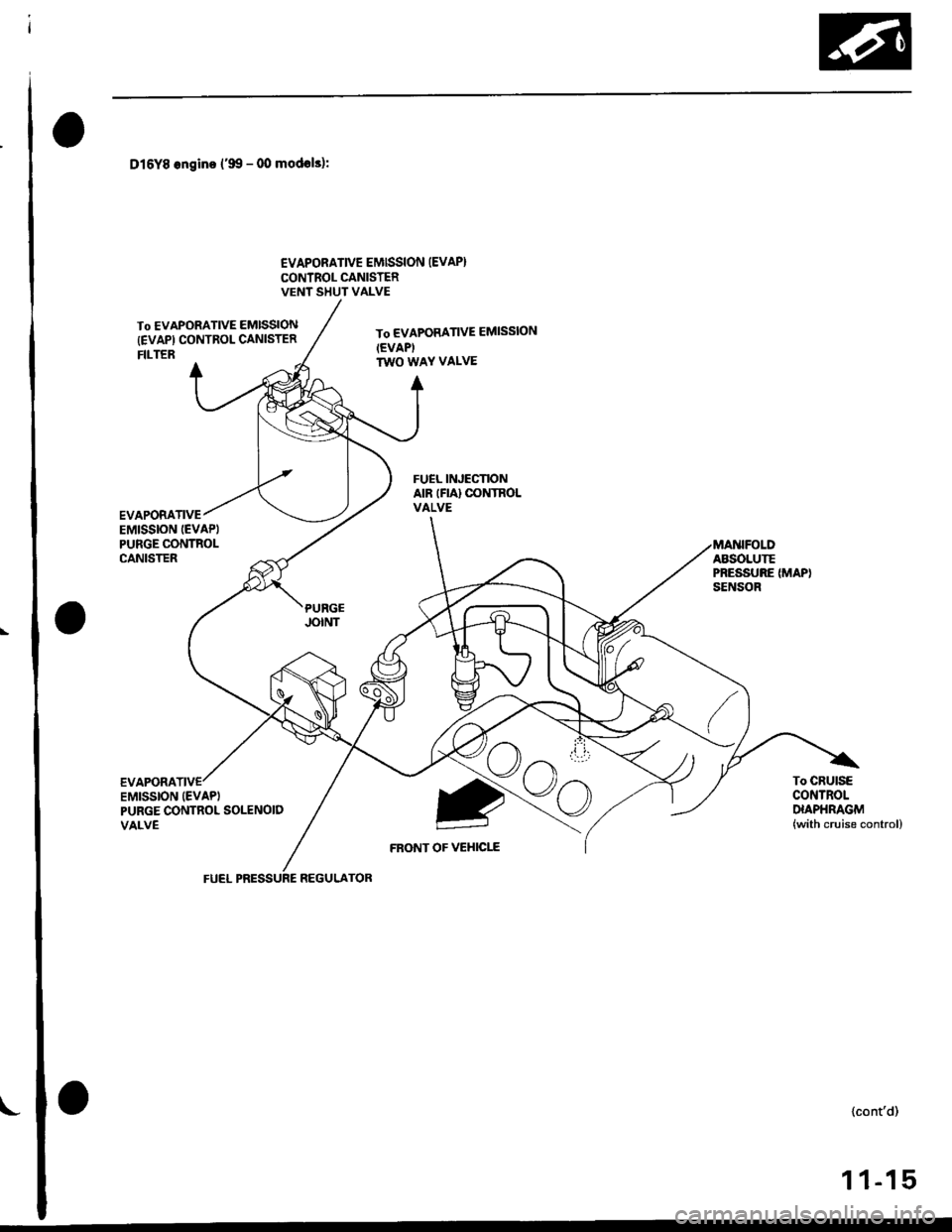
Dl6Y8 ongino ('99 - 00 modols):
€VAPORATIVE EMISSION (EVAP}
CONTROL CANISTERVENT SHUT VALVE
To EVAPORATIVE EMISSION
{EVAPI CONTROL CANISTERFILTER
To EVAPORATIVE EMISSION(EVAPI
TWO WAY VALVE
FRONT OF VEHICI-E
To CRUISECONTROLDIAPHRAGM(with cruise control)
EVAPORATIVEEMISSION IEVAPIPURGE CONTNOLCANISTER
REGULATOR
{cont'd)
1 1-15
Page 285 of 2189
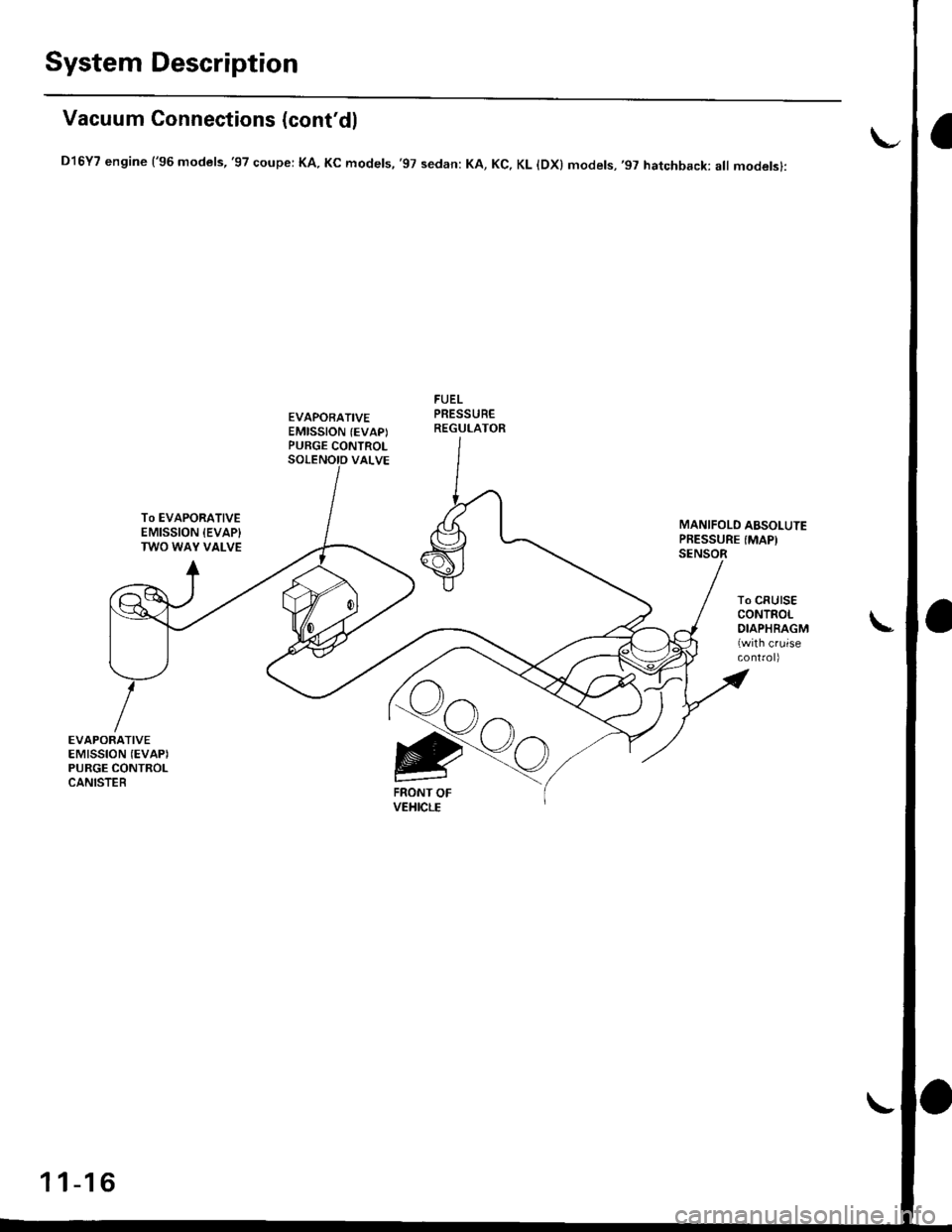
System Description
Vacuum Connections (cont'dl
D16Y7 engine ('96 models,'97 coupe: KA. Kc models, '97 sedan: KA, Kc, KL lDx) models,'97 hatchback: all modelsl:
EVAPORATIVEEMISSION (EVAPIPURGE CONTROL
FUELPRESSUREREGULATOR
To EVAPORATIVEEMISSION {EVAP}TWO WAY VALVE
MANIFOLD ABSOTUTEPRESSURE (MAP)
To CRUISECONTROLDIAPHRAGMlwith cruise
EVAPORATIVEEMISSION (EVAPI
PURGE CONTROLCANISTERFRONT OFVEHICLE
11-16
Page 286 of 2189
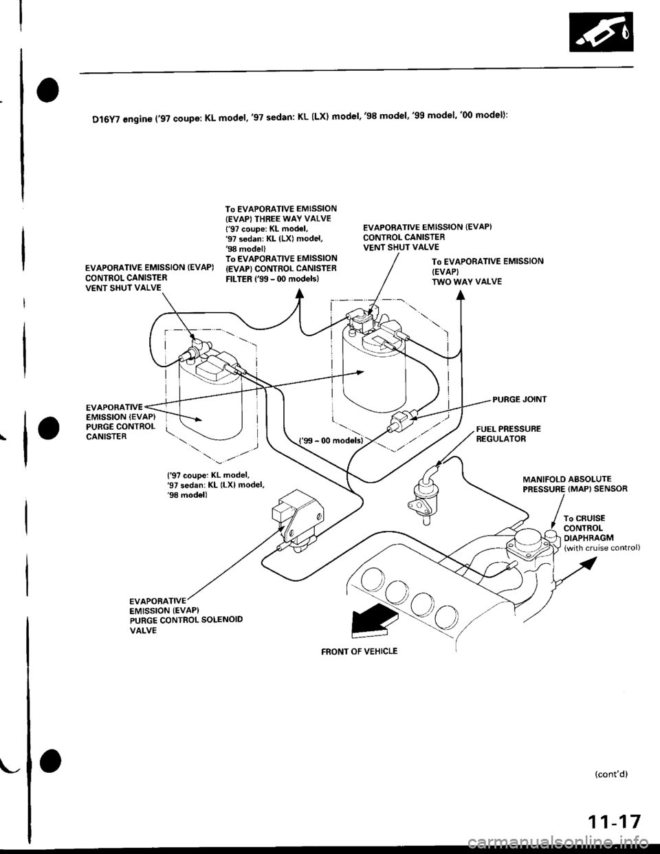
Dl6YT engine ('97 coupe: KL model,'97 sedan: KL ILX) model,'98 model"gg model"oo model):
To EVAPORATIVE EMISSION{EVAP} THREE WAY VALVE
l'97 coupe: KL model,'97 sedan: KL (LX) model,'98 modellTo EVAPORATIVE EMISSION
{EVAP) CONTROL CANISTER
FILTER ('99 - 0O models)
EVAPORATIVE EMISSION {EVAP)CONTROL CANISTERVENT SHUT VALVE
EVAPORATIVE EMISSION (EVAP)
CONTROL CANISTERVENT SHUT VALVE
To EVAPORATIVE EMISSIONIEVAPITWO WAY VALVE
PURGE JOINTEVAPORATIVEEMISSION {EVAP}PURGE CONTROLCANISTERFUEL PRESSUREREGULATOR_.\,,..,_..-.
{'97 coupe: KL model,'97 sedan: KL (LX) model.'98 model)
MANIFOLD ABSOLUTEPRESSURE {MAP) SENSOR
To CRUISECONTROLDIAPHRAGM
lwith cruise control)
EVAPORATIVEEMISSION (EVAP}gtt
FRONT OF VEHICLE
PURGE CONTROL SOLENOID
VALVE
(cont'd)
11-17
Page 287 of 2189
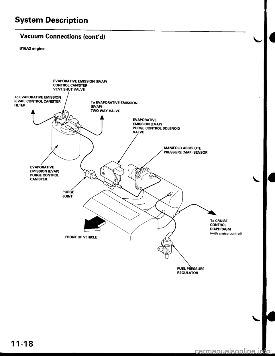
System Description
Vacuum Gonnections (cont'd)
B16A2 engine:
EVAPORATIVE EMISSION (EVAPICONTROL CANISTERVENT SHUT VALVE
To EVAPORATIVE EMISSION(EVAPI CONTROL CANISTERFILTER
EVAPORATIVEEMISSION {EVAPIPURGE CONTROLCANISTER
To EVAPOBATTVE EM|SS|ON(EVAPI
TWO WAY VALVE
EVAPORATIVEEMISSION IEVAPIPUBGE CONTROL SOLENOIDVALVE
2
VEHICLE
MANIFOI.D ABSOLUIEPRESSURE (MAPI SENSOR
FUEL PRESSUREREGULATOR
To CRUISECONTROLDIAPHRAGM(with cruise control)
1 1-18
Page 361 of 2189
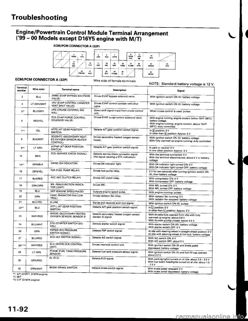
Troubleshooting
Engine/P_o,wertrain Control Module Terminal Arrangement('99 - 00 Models except Dl6Y5 engine with M/Tl
ECM/PCM CONNECTOR A (32P)Wire side ot temale terminalsNOTE:Standard battery voltage is l2 V
ECM/PCM CONNECTOR A I32PI
Sign!l
3BLU2WSS (EVAP 8YPAsS SOLENOIDDrives EVAP bypass solenoid vatve,With gn'tion swnch ON (lll banery votlage
LT GRN/I/VIITVSV {EVAP CONTNOL CANISTERVENTSHUTVALVE]Drives EVAP controt ca n isrer v€nt shutWilh ignilion switch ON {tl): b€ttery vottage
8LU/GNNC8S (CRUISE CONTSOL SIGOown shift signal inpot lrom c.uise conrrolWhen crurss control is used:purses
68ED/YELPCS {EVAP PURGE CONTROLSOTENOIOVALVE)Drives EVAP purge conrrol sotenoid vatve.With engine running, engine cootant, betow r54.F (6a,C):
With engine.unning, €ngine coolant, abov€ 154.F(68'C): duty conlrolled
YELATPD {AT GEAR POSITIONSWITCH)ootects A/T gear posnion swilch s,gnar.In otherthan @ posilion: Apprcx. 5 V
8BLK,IflHTSO2SHTC (SECONDARY HEATED OXYGEN SENSOS HEATEFCONTFOL)
Drives sscondary h€ared oxygen senso.Wilh isn,rion swirch ON (ll):banery votraseWith lully warm6d dp€ngire runn'ng:dury controled
LT GRNATPNP (AT GEAF POSITIONSWITCH)oereds A/T 9€a r position switch signat.In Parr or neulrsl:0 VIn anyother position approx.5 v
t088NSCS (SERVICE CHECK SIGNAL)Oetects ssruice check connecror signal(the signalcausing a OTC indication)with rh€ t6rminal connected: 0 vWith the rerm ina I disconneded: abour 5 V of ban€ry
GNN/BIKD4IND (D4INDICATON]Drives Oa indicaio. lighr.With D4 indicator lightturned ON: O VWith D4 indicator lightturned OFF: battery vo ttageG8N/YETFTF (FUEL PUI\,4P SELAY)Orivos tuel pump relay,0V for two s€conds lfrer turnrng rgnilior swtcn ON(ll), then batt€ry voltage11BTI(REDACC (Al/C CTUTCH SELAY)Drives A./C clutch reray.With compressor ON:O VWilh comp.ssor OFF; battery vottage18GFN/OFNMI! (A,IAIFUNCTION INDICA.TOF LIGHT)With MlLturned ON:0 VWith l\,llL tornod OFF|batrery votrsge198tuNEP (ENGINE SPEED PUTSEIOulputs6ngine speed pulse,Wilh engin6.unning: putses
20GFNFANC {SADIATOR FAN CONTnoL)Orives radiarortan relay.Wirh r.distor t6n running:OVWith radiatortan stopped: banery vottage21ELUA/ELK LINESends and r€ceives s.an lool signal.With ignition switch ON (ll):p!ts€s
22'lBLUATP L {AT GEAS POSITIONswtTcH)Oelocis A"/T gear posirion switch siSnat.In othfflhan E position: Apprcx. 5 V
23SHO25 (SECONOARY HEATEDOXYCEN SENSOR, SENSOF 2)Detects secondsry hoar€d oxygen sensorWith lhronle f! lly or'6ned from idte with fu ywarmod up engine: above 0.6 vWiih th.onl6 quickb, closd:below 0,4 V24STS ISTAFTEN SWITCH SIGDebcrs staner switch signat.Wirh srarterswitch ON (tttJ: batteryvottogeWith sraftsr cwirch OFF:0 V26GFNPSPSW iPlS PNESSURESWITCII SIGNAL)Derecrs PSP switch signat.Atidle with steoring wheolin srraightahead position: O VAt idl6with steering wheetal fult lock: barery vo ttags27BLU/REOACS (AJC SWITCH SIGNALJOer*ts ,ay'C swirch signat.Wiih ty'C switch ON;0VWilh Ay'C switch OFF|aboor 5VWHT/REDSLU iINTERLOCK CONTROIUNIT)Drivos interloct control unit.With ignltion switch ON (ll)and brake pedaldepresed: batlory volrage29LT GRNPTANK (FUEL TANK PFESSUEESENSOR)Oer6ds lu€l tank pr€ssura sonsor signat.Wilh ig.rrrd swirch ON rttr and fuetti
cap ooen6d.
30GRN/FEOEr (ELOIWith parking lighlsrurned on ar idteiaboui 2.5- 3.S VWirh low beam he€dlig hts turnqd on ai idts: aboul 1.52.5 V32GRN/'WHTAKSW (BFAKE SWITCH)Detets brak€ swrtch signEt,With brake pedal r6l€ased:0 VWhh brake pedaldepres*d: battery voltEse'1:A./T (D16Y7, D16Y8 engine)*2: rvt/T13: CVT (D16Y5 engine)
11-92
Page 1091 of 2189
Steering Wheel
l,/
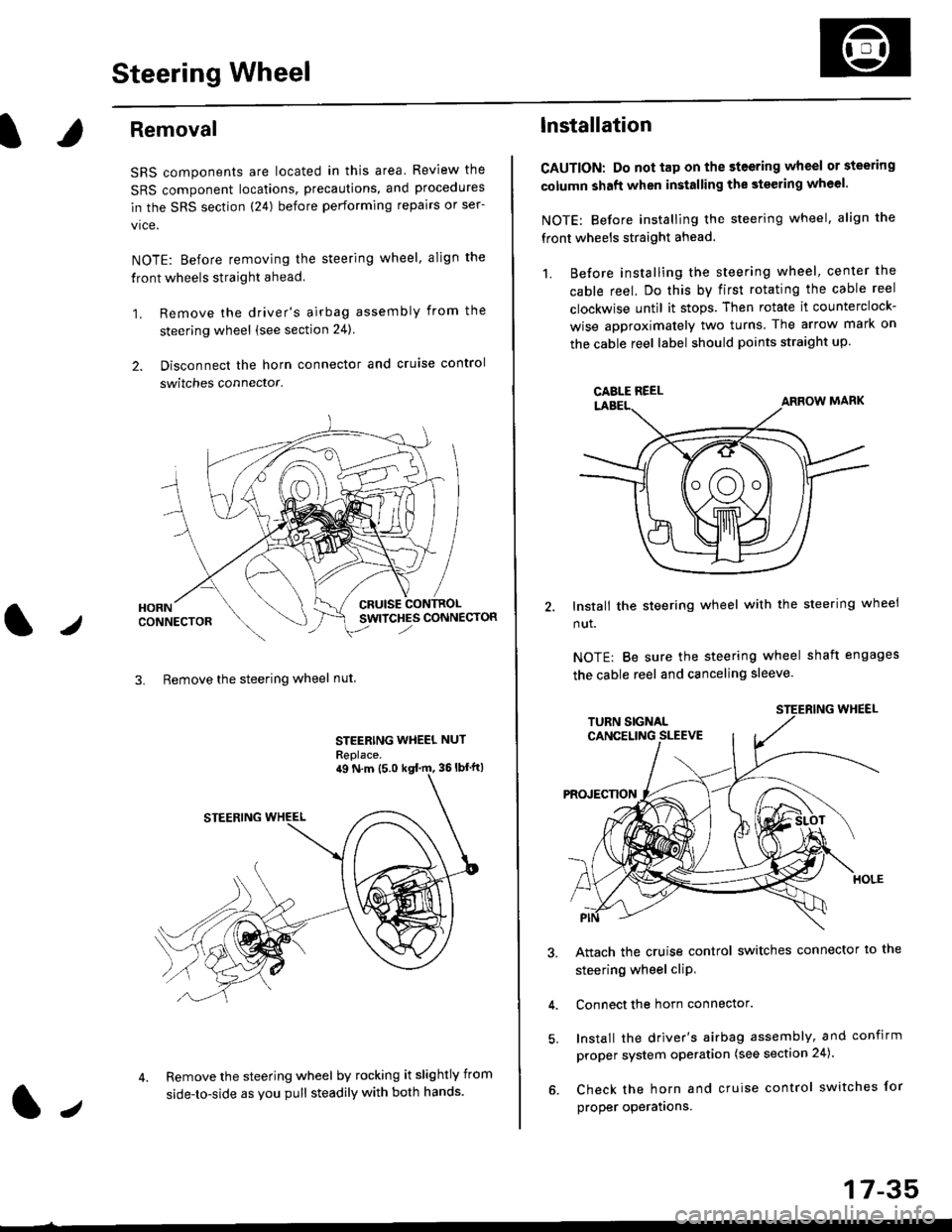
Removal
SRS components are located in this area Review the
SRS component locations, precautions, and procedures
in the SRS section (24) before performing repairs or ser-
vice.
NOTE: Before removing the steering wheel. align the
front wheels straight ahead.
1. Remove the driver's airbag assembly from the
steering wheel (see section 24)
2. Disconnect the horn connector and cruise control
switches connector.
CRUISESWITCHES CONNECTOR
3. Remove the steering wheel nut
STEERING WHEEL NUT
Replace.
Remove the steering wheel by rocking it slightly from
side-to-side as you pull steadily with both hands.
ag N.m {5.0 kgt rn, 36lbfft)
1.,
17-35
lnstallation
CAUTION: Do not tap on the steering wheel or steering
column shaft when installing the stsering wheel.
NOTE: Before installing the steering wheel, align the
front wheels straight ahead.
1. Before installing the steering wheel, center the
cable reel, Do this by first rotating the cable reel
clockwise until it stops. Then rotate it counterclock-
wise approximately two turns The arrow mark on
the cable reel label should points straight up.
Install the steering wheel with the steering wheel
nut.
NOTE: Be sure the steering wheel shaft engages
the cable reel and canceling sleeve.
Attach the cruise control switches connector io the
steering wheel cliP,
Connect the horn connector.
Install the driver's airbag assembly, and confirm
proper system operation (see section 24).
Check the horn and cruise control switches for
proper operatrons.
CAELE REEL