C131 HONDA CIVIC 1998 6.G Owner's Manual
[x] Cancel search | Manufacturer: HONDA, Model Year: 1998, Model line: CIVIC, Model: HONDA CIVIC 1998 6.GPages: 2189, PDF Size: 69.39 MB
Page 1901 of 2189
I -.. t
iecnuaruerirt Rererence rp iiftii* l"*o, $'n"o.
t
.i sensor Input voltaqe sensor input inpul input inp"r II TEGFL' rvca?r Opsl rFirir.rxt rECn i,ari tL------- _______.J
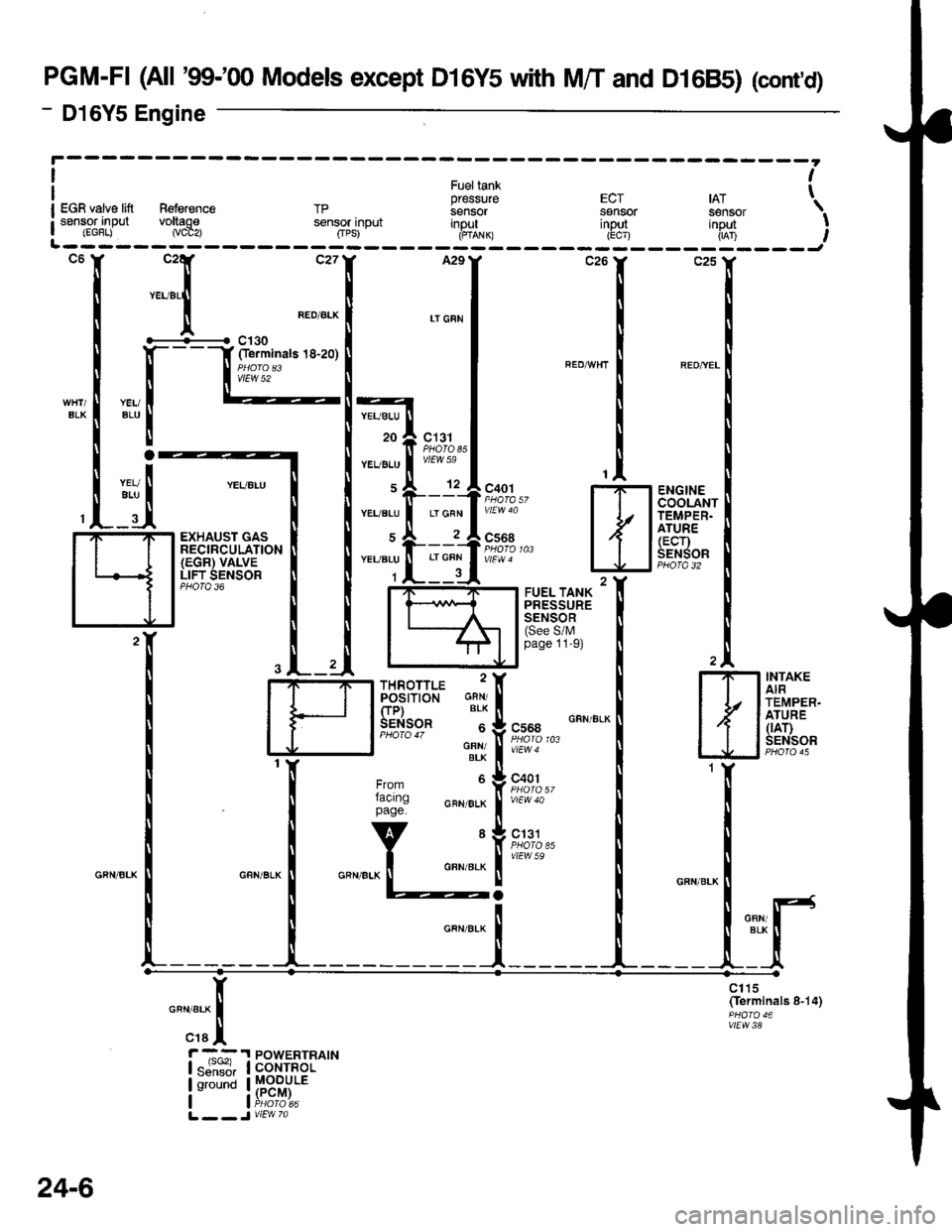
PGM-FI (All '99-'00 Models except D16Y5 with M/T and D16B5) (cont,d)
- D16Y5 Engine
BLK
c131PHOTOssvtEW 59
ENGINECOOLANTTEMPER.ATURE(ECr)SENSORPBO|A 32
c130Oerminals 18-20)
vtEW 52
YEUALU
20
YEUALU
YEUALU
YEUBLU
1
YEUBLU
ALU
LT GFN
EXHAUST GASRECIRCULATION(EGR) VALVELIFT SENSORPHO|O 36
TEMPER.
tllfrtr'l
I J tffiT,.:'
""",:I
1r:{
Slt or
lr;: H
H#*iiff''I
fi[ffi,''""."'.1
"_
[;,l;,+. N
:{I
c1t5(ferminals 8-14)
vtEw38
n"","*[
"raI
r -,^^:.I POWERTRAIN| "ji""il, I corrnor
lu'"t !H"3fii:'L __ J V|EW 7a
24-6
Page 1912 of 2189
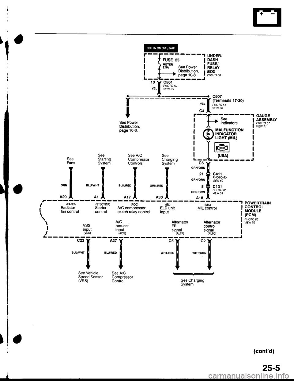
@----t UNDER.
I t FUSE 2s I p.4:!
| ) Iff" ses Power | ;"Eiii
I l------+ 3l'i:?'J:" tF,%.,L--*----il--l-J -
'o Y F;%.YELI v/Ew 55
f
--- - - - - - - - - - -;f '-iminats tz'zo1
I c+ lv'rwto
Y r--'1r-:-----'l GAUGE
see Power ! f* l"?i*,".. ! f,s";"ty"ttDisiribution, I , | vtEwTlpass10'6
i @$eFH,t* i
! T16r I
see see !y'c see I I
-ruil |See Startrnq ComDressor Charorno L--V---J----JFans System Conliols Syste-m - C5 y
I I I I
"".11-lro,..
| | | | o"no"n!f[?iSuo
GUN
I
BLUVHT
I
BLKnEo
I
GRNFED
f sVC131
*o I o, .1. o', ,l o.o .l
o"*o*l i[?1o"*
,r---U,a"i---strF-*-*"r"tr8*i-#%,.----;w;,---lneffi [it^'" tan control control ciutch reiay control Input | (pCM) -._ | puoroear AJc Atternaror Atternator l. iir*.i VSS rsquest FR controt I
i '[g3l i"R8!, ",gl,1o "'11'%, IrL------ --------Jc23 ll, l27Y "ur "rX
tlllBtUw}rI
I
BLU,FEo
I
w8r RED I wxr onr I
IIIIYYYY
See Vehicle See A,/C -'-dSpeedSensor Compressor(vss) contiot 3i:,""I"'n'"n
(cont'd)
25-5
I
Page 1926 of 2189
85'[ru*,, 'l*u,*
wiz-"ln*"
-a
I
le
.il
c131
vtEW 59
----sgr
c410
vlEw 35
LT GFN
12
LT GFN
-----1 A/T GOrr
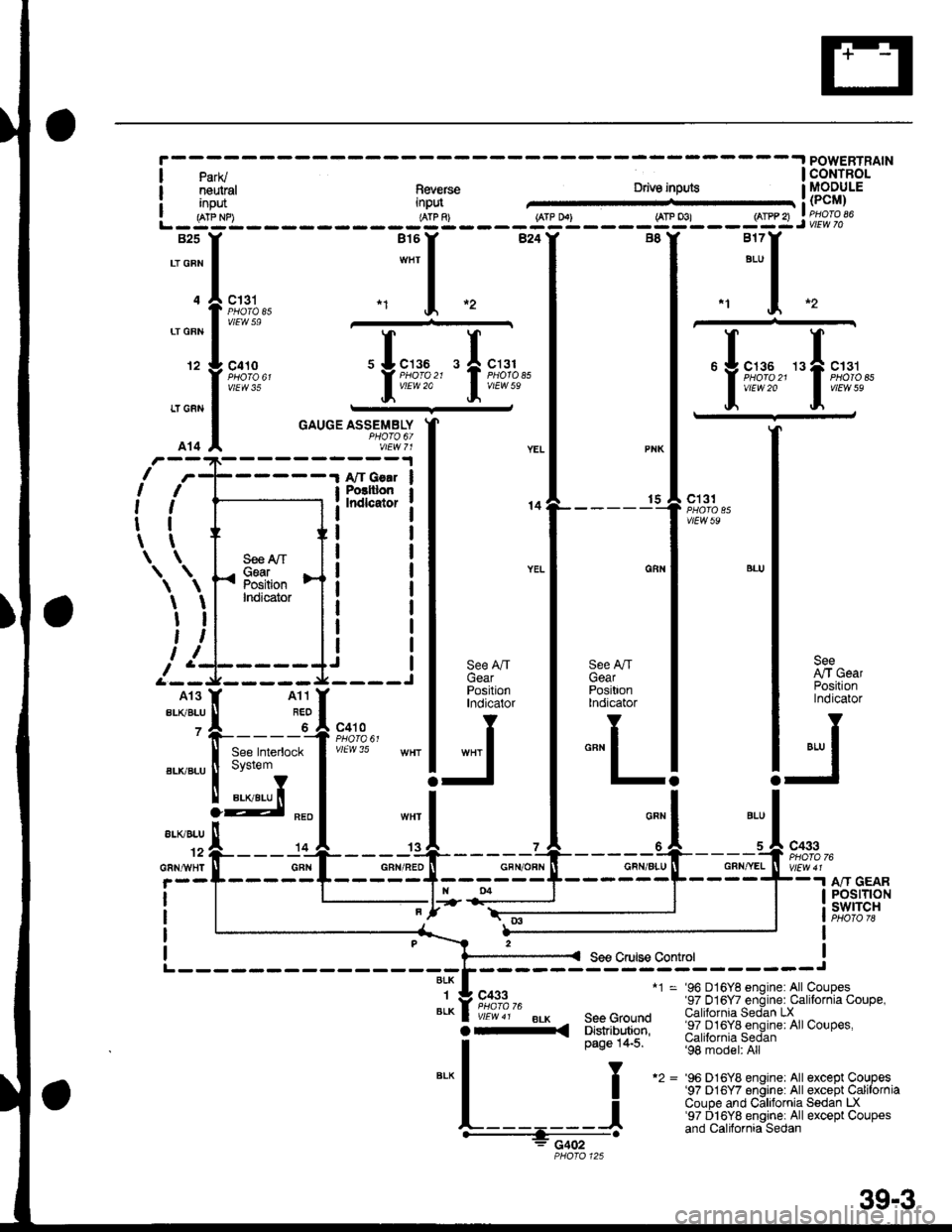
GAUGE ASSEMBLYPHOTO 6/vlEw 71
I Posttlon
i Indlcator
I
I
I
I
I
I
IJ
14
\
I
I
II
A
I
I
I
I\
\
1
I
,
I
I
I
I
t
t
\
\
a)
S€e A,/TGearPositionIndicator
c4t0
vlEvl 35
'96 D16Y8 enqine: All Coupes'97 016Y7 engine: Calilornia Coupe,California Sedan LX'97 D16Yg engine: AllCoupes,California Sedan'98 model: All
'96 D16Y8 enqrne: All exceot CouDes'97 D16Y7 en6tne: All except CaliiorniaCoupe and Caftfornia Sedan LX'97 Dl6Y8 enginei All except Coupesand California Sedan
See A/TGearPositionlndicator
*"r I
-
----s+----+="1--'-scFN/AlU ll GRNryEL ll vEwar_----F----*-r nr cenn| | | POSITION| ; swlrcHt I oTo78
I
see cruise control I
{GBN/RED N'---1;'
'--T-)tn
39-3
Page 1931 of 2189
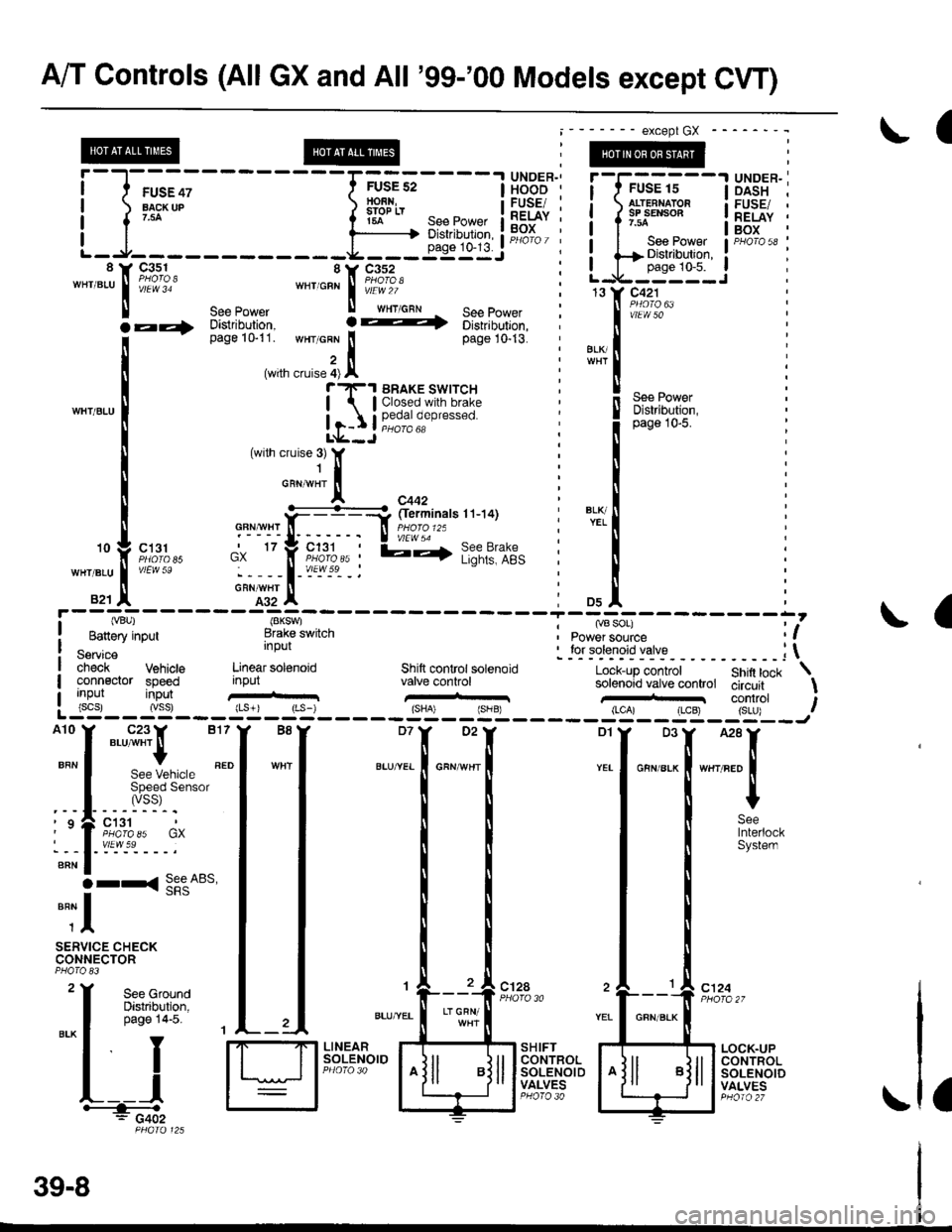
A/T Controls (All GX and All '99-'00 Models except CVI)
a
i-l-;;;
-rffi;----t
H*B'""i
! l r*-* i iflsln- :eepower ii|iii '
L_l____ _-i"utuiF#'i8 Y 93-s_1 SY C3s2 :""'".u I i,i?lol *"'o"n I iffl,1of
ll see eower ll wxrcnl - see power :
@
c131
vlEw 59
See GroundDistribulion,page 14-5. 1
["*
t*,t*;,,
;ffi i-
iilnirir,
Distribution,page 10-5.
,D5
, ry8 SOr)I Power source
BLI(YEL
il
10
WHT/BLU
821
(VBU)
Banery input
Servicecheck Vehicls Linear sol€noidconneclor speednput
' for solenoid valve ; \
Lock-up controlsolenoid valve (valve control circuitShift lock \
c'124
a
inpulinput
{8KSW)Brake switchInput
Shilt control solenoidvalve control
:::l
",:::[""::
. | .ir:Til**'
''lizll:l,,' i*'";l'-.----.'
O rr<( !!e"A65,
""il
SERVICE CHECKCONNECTOR
c12A
LTGRN/
I
SH IFTCONTROLSOLENOIDVALVES
LOCK.UPCONTROLSOLENOIDVALVESL__l+: G402a
il*-
except GX
See Powerr?F.| BRAKE SWTTCH
| | Closed with brake
| 1-I | !;€ja oeo'"""o
39-8
Page 1938 of 2189
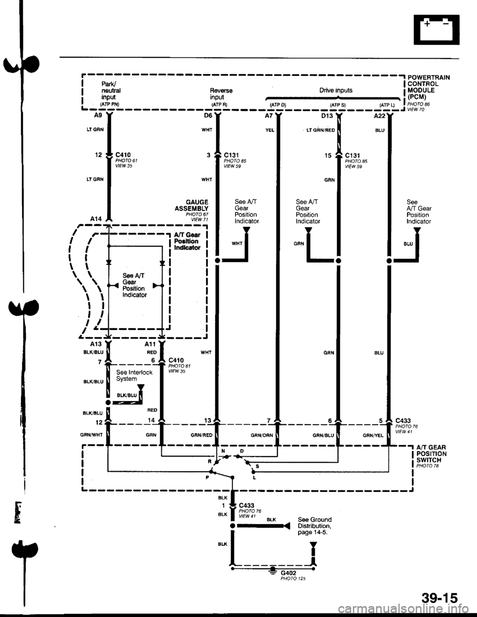
A9
LT GFr'l
12
LT GFN
A14
c410
vtEw 35
c131PHATA E5vtEw 59
D't 3
tT GRN/FED
15
GRN
See A./TGearPositionlndicator
"""L
c131
vtEw 59
WHT
GAUGEASSEMBLYPHO|O 67vtEw 71
See AfrGearPositionIndicator
wxr I
-
SeeArt GearPositionIndicator
"',, I
-l
I
lt
,l
tl
tt\
\
I
I
t
,,I
I
I
I
t
\
AII GsarPoclllonkldlcrtor
a
S€€ A/TGearPositionIndicator
Ii
fsn$t';
!d
c410
vtEw 35
c433
A/T GEARPOStTtONSWITCH
c433
BLKSee Gaounda-< Disaibdion,
| *o" to-t
"'*l
Y
t________l'--- -gcji-
PHOIO 125
--*
BLK
1
6LK
39-15
Page 1979 of 2189
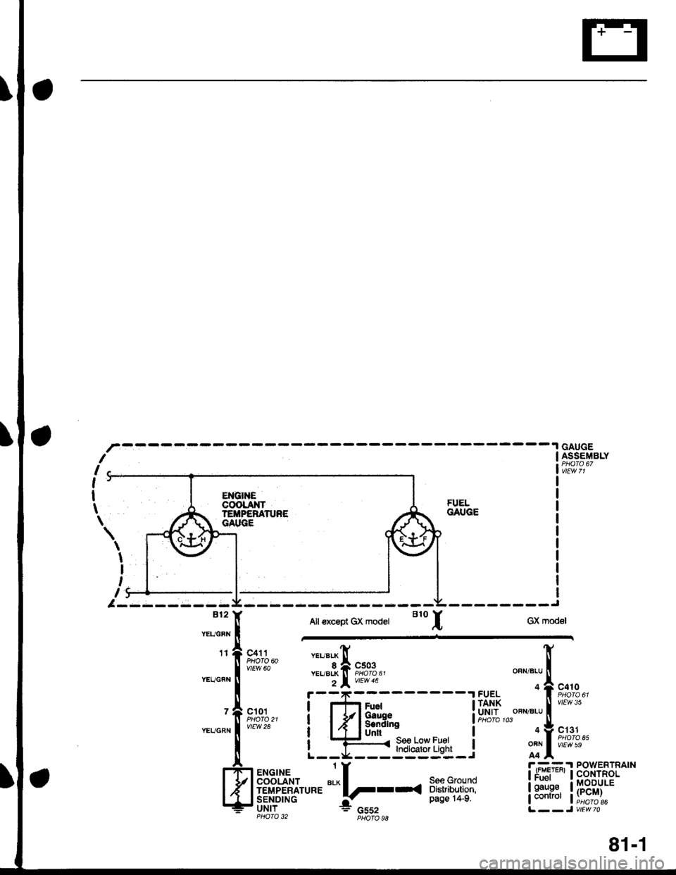
GAUGEASSEMBLYf
l-*
,'
I
t
\
\
I
I
,
,:
ENGlrlECOOLANTTEiTPERATNEGAI'GE
FUELGAUGE
--------J
GX modelBl2
tr' Alt€xcsp't Gx mod€t B1o
IYEUGFN I
,r, A "oll "., ","11"
fi;rt"r4." ,1,"g[ s;g,,YEUGFN I 2lvtuea
r-----.|FUEL
- A ^.^. I |fl Fuer lll,l5
-*"L[
F*H4''
L
t#4iorn-i'**
-
t '-;5-
OFN/BLU
OFN/BLU
OFN
A4
c410
vlEw 35
c131
vtEw 59
r --= .I POWERTRAIN
!r+i-'' !fi8tsllP.
331ffi !i;E-i/'i
#."o,". t f
14
ii11"t:'f""'
*!--*
il?:+:ifll--JvtEwzo
81-1
Page 1993 of 2189
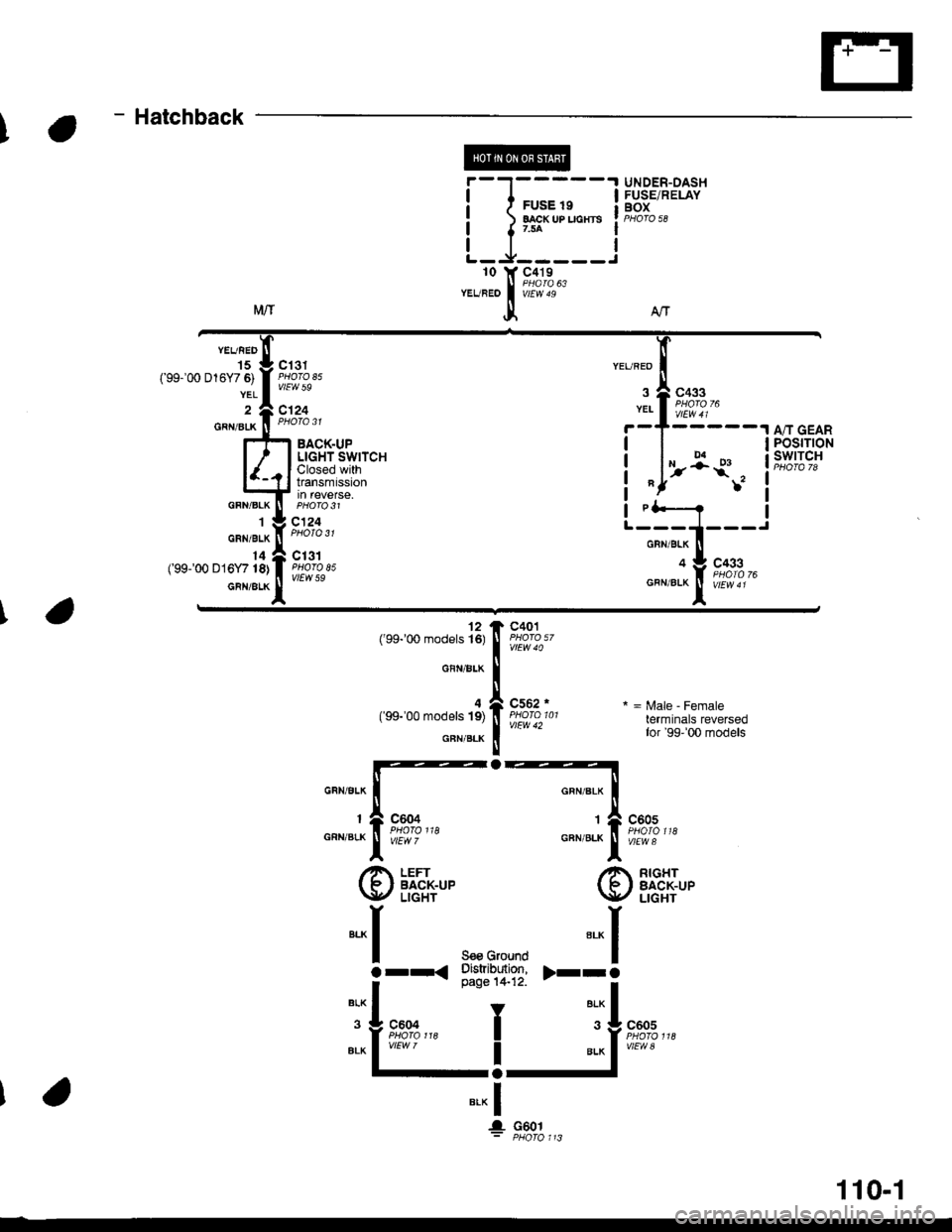
I
Hatchback
tr@
UNDER-DASHFUSE/RELAYBOX
YEVRED
15('99-'00 D16Y7 6)
YEL
GRN/BLK
GFN/BLK
1
GRN/BLK
14(99-'00 D16Y718)
GBN/ALK
c433
vtEW41
POSTTTONswrTcH
c13tPHOTO A5vlEw 59
c'|24
,5i*
YEUREO
YEI
I
IL
BACK"UPLIGHT SWITCHClosed withtransmtsstonin revetse.
c124
c131PHOfO 85vtEw 59
rl*--? i-;;1---'�
o I co..
12('99100 models 16)
GFN/BLK
4('99-'00 models 19)
GFN/BLK
c401
c552 rPHOTO 101vlEW 42
o
*=irale-Female
terminals reversedtor '99' 00 models
@ i[T,'+'"
-*1
orr<
G
""",Jfi fiT,,3,*
@|,LHI"'
s€ecround
--l
i'""#'T?!: t-Ti"...
I
"l9t*,,,
lJJ"''"'
I
I
BLK
ALK
c604
.! c6ol
110-1
Page 2143 of 2189
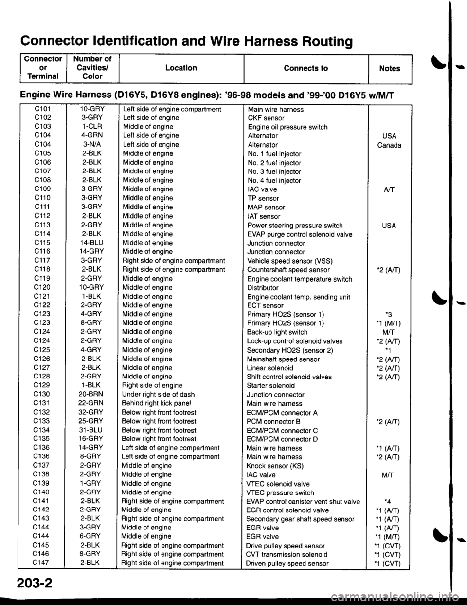
Connector ldentification and Wire Harness Routing
Connector
or
Terminal
Number ot
Cavities/
Golor
LocationConnects toNotes
Engine Wire Harness (Dl6Y5, D16Y8 engines): '96-98 models and '99;00 D16Y5 dM/T
c101
c102
c 103
c104
Q104
c105
c106
c107
cl 08
cl09
cl10
c1l1
cl'12
c113
c114
c'115
c116
c'117
c 118
c119
c120
c121
c122
c123
c123
c124
Q124
c125
c 126
c127
c128
c129
c130
c131
cl32
c 134
c135
c136
c137
c138
c139
c'140
c141
c142
c143
c144
c'|44
c145
c146
c147
1O-GRY
3.GRY
1-CLR
4-GRN
3-N/A
2-BLK
2-BLK
2-BLK
2-BLK
3-GRY
3-GRY
3-GRY
2.BLK
2.GRY
2-BLK
14-BLU
14-GRY
3.GRY
2-BLK
2-GRY
1O-GRY
1.BLK
2.GRY
4-GRY
8-GRY
2-GRY
2.GRY
4-GRY
2.BLK
2.BLK
2-GRY
1.BLK
2O.BRN
22.GRN
32.GRY
25.GRY
31-BLU
16.GRY
14-GRY
8.GRY
2-GFIY
2.GRY
1-GRY
2-GRY
2-BLK
2-GRY
2.BLK
3-GRY
6-GRY
2.BLK
8-GRY
2-BLK
Left side of engine compartment
Left side of engine
Middle of engineI att .i.la ^f an^i^6
Left side ot engine
Middle of engine
Middle of engine
Middle of engine
Middle of engine
Middle of engine
[,liddle of engine
Middle ot engine
Middle ot engine
Middle of engine
Middle of engine
Middle of engine
l\,liddle of engine
Right side of engine compartment
Right side of engine compartment
Middle ot engine
Middle of engine
Middle of engine
Middle of engine
l\,liddle of engine
Nliddle of engine
Middle ot engine
Middle of engine
Middle ot engine
Middle of engine
Middle of engine
Nliddle of engine
Right side of engine
Under right side of dash
Behind right kick panel
Below right front footrest
Below right front footrest
Below right front footrest
Below right front tootrest
Left side ot engine compartment
Left side of engine compartment
Middle of engine
liliddle ot engine
Middle of engine
Nriddle ol engine
Right side of engine compartment
Middle ol engine
Right side of engine compartment
Middle of engine
N,liddle of engine
Right side of engine compartment
Right side of engine compartment
Bight side of engine compartment
Main wire harness
CKF sensor
Engine oil pressure switch
Alternator
Alternator
No. 1 fuel injector
No. 2 fuel injector
No. 3 fuel injector
No.4 fuel injector
IAC valve
TP sensor
MAP sensor
IAT sensor
Power steering pressure switch
EVAP purge control sol€noid valve
Junction connector
Junction connector
Vehicle speed sensor (VSS)
Countershatt speed sensor
Engine coolant temperature switch
Distributor
Engine coolant temp. sending unit
ECT sensor
Primary HO2S (sensor '1)
Primary HO2S (sensor '1)
Back-up light switch
Lock-up control solenoid valves
Secondary HO2S (sensor 2)
lvlainshafl speed sensor
Lanear solenoid
Shift control solenoid valves
Starter solenoid
Junction connector
Main wire harness
ECM/PCM connector A
PCM connector B
ECM/PCNI connector C
ECM/PCl\,,| connector D
Main wire harness
Maln wire harness
Knock sensor (KS)
IAC valve
VTEC solenoid valve
VTEC pressure switch
EVAP control canister vent shut valv€
EGR control solenoid valve
Secondary gear shatt speed sensor
EGR valve
EGR valve
Drive pulley speed sensor
CVT transmission solenoid
Driven pulley speed sensor
USA
Canada
AlT
USA
'2( tr\
'3
-1 (M/r)
t\4/T'2 (Anl'1
'2 (An)'2 (Nr)'2 (AtT)
'2 (Atr)
-1 (An)-2( fi|
M/T
.1 (Arr).1 (A,T)"1 (A/r)-1 (M/r).1 (CVT),1 (cw)'1 (CVT)
203-2
Page 2147 of 2189
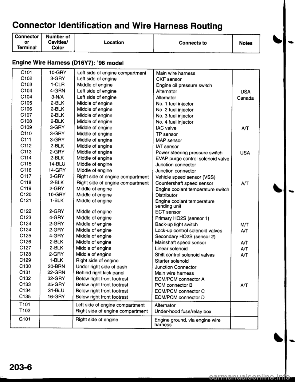
Connector ldentification and Wire Harness Routing
Connector
or
Terminal
Number of
Cavities/
Color
LocationConnects toNotes
Engine Wire Harness (Dl6Y7): '96 model
c101
c102
c103
cl04
c104
c 105
c106
c107
c108
c109
c110
c111
c112
c11 3
c114
c115
c116
c117
c118
c119
c120
c121
c122
c123
c124
cl24
c125
c126
c127
cl28
c129
c130
c131
cl32nl2?
c134al eR
1O.GRY
3-GRY
4.GRN
3-N/A
2.BLK
2-BLK
2-BLK
2-BLK
3.GRY
3-GRY
3.GRY
2-BLK
2.GRY
2-BLK
14-BLU
14-GRY
3.GRY
2.BLK
2-GRY
1O-GRY
1 -BLK
2-GRY
4.GRY
2.GRY
2-GRY
4-GRY
2.BLK
2-BLK
2-GRY
1-BLK
2O-BRN
22-GRN
32.GRY
25-GRY
31-BLU
16.GRY
Left side of engine compartment
Left side of engine
Middle of engine
Left side of engine
Lefl side of engine
Middle of engine
Middle of engine
Middle of engine
Middle of engine
Middle of engine
Middle of engine
Middle of engine
Middle of engine
Middle of engine
Middle of engine
Middle of engine
Middle of engine
Right side of engine compartment
Right side of engine compartment
Middle of engine
Middle of engine
Middle of engine
Middle of engine
Middle of engine
Middle of engine
Middle of engine
Middle of engine
Middle of engine
Middle of engine
Middle of engine
Right side of engine
Under right side of dash
Behind right kick panel
Below right front footrest
Below right front footrest
Below right front footrest
Below right front footrest
Main wire harness
CKF sensor
Engine oil pressure switch
Alternator
Altemator
No. 1 fuel injector
No. 2 fuel injector
No. 3 fuel injector
No. 4 fuel injector
IAC valve
TP sensor
MAP sensor
IAT sensor
Power steering pressure switch
EVAP purge control solenoid valve
Junction connector
Junction connector
Vehicle speed sensor (VSS)
Countershaft speed sensor
Engine coolant temperature switch
Distributor
Engine coolant temperaturesending unit
ECT sensor
Primary HO2S (sensor 1)
Back-up light switch
Lock-up control solenoid valves
Secondary HO2S (sensor 2)
Mainshaft speed sensor
Linear solenoid
Shift control solenoid valves
Starter solenoid
Junction Connector
Main wire harness
ECM/PCM connector A
PCM connector B
ECM/PCM connector C
ECM/PCM connector D
USA
Canada
A/T
USA
Atf
Aff
M/T
Arl
AtT
A/T
Afi
T101
T102
Left side of engine compartment
Right side of engine compartment
Alternator
Under-hood fuse/relay box
G101Right side of englneEngine ground, via engine wirenarness
203-6
Page 2149 of 2189
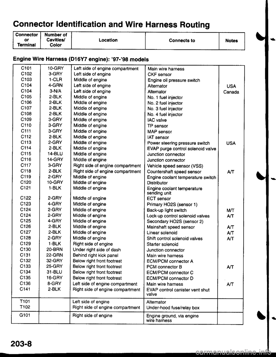
Connector ldentification and Wire Harness Routing
Connector
or
Terminal
Number of
Cavities/
Color
LocationConnects toNoles
Engine Wire Harness (Dl6Y7 engine): '97-'98 models
c101
c102
c103
c104
c104
c105
c106
c107
c108
c109
c110
c111
c113
c114
c115
c116
c118
c119
c'120
c121
c122
c124
c124
c125
c126
c127
c128
c129
cl30
c131
c132
c133
c134
c135
\, | 'tO
c141
1O-GRY
3-GRY
1.CLR
4.GRN
3.N/A
2-BLK
2-BLK
2-BLK
2-BLK
3.GRY
3-GRY
3-GRY
2-BLK
2.GRY
2-BLK
14.BLU
14.GRY
3.GRY
2-BLK
2-GRY
lO.GRY
1-BLK
2-GRY
4.GRY
2.GRY
2-GRY
4.GRY
2.BLK
2.BLK
2-GRY
1-BLK
2O-BRN
22-GRN
32-GRY
25.GRY
31-BLU
16.GRY
8-GRY
2-BLK
Lefl side of engine compartment
Lett side of engine
Middle of engine
Left side of engine
Lefl side of engine
Middle of engine
Middle of engine
Middle of engine
Middle of engine
Middle of engine
Middle of engine
Middle of engine
Middle of engine
Middle of engine
Middle of engine
Middle of engine
Middle of engine
Right side of engine compartment
Right side of ongine compartmont
Middle of engine
Middle of engine
Middle of engine
Middle of engine
Middle of engine
Middle of engine
Middle of engine
Middl€ of engine
Middle of engine
Middle of engine
Middle of engine
Right side of engine
Under right sido of dash
Behind right kick panel
Below right front footrest
Below right front footrest
Below right front footrest
Below right front footrest
Left side of engine compartment
Right side of engine compartmsnt
Main wire hamess
CKF sensor
Engine oil pressure switch
Alternator
Altemator
No. 1 fuel injector
No. 2 fuel iniector
No. 3 fuel iniector
No. 4 fuel injector
IAC valve
TP sensor
MAP sensor
IAT sensor
Power steering pressur€ switch
EVAP purge control solenoid valve
Junction connector
Junction connector
Vehicle speed sensor (VSS)
Countershaft speed sensor
Engine coolant temperature switch
Distributor
Engine coolant temperatu resenorng unI
ECT sensor
Primary HO2S (sensor 1)
Back-up light switch
Lock-up control solenoid valves
Secondary HO2S (sensor 2)
Mainshaft speed sensor
Linear solenoid
Shift conirol solenoid valves
Starter solenoid
Junclion connector
Main wire harness
ECM/PCM connector A
PCM connector B
ECM/PCM connector C
ECM/PCM connsctor D
Main wire harness
EVAP control canister vent shutVAIVE
USA
Canada
USA
Nf
A/T
M/T
A/T
Atl
An
AIT
NT
T101
T102
Left side of engine
Right side of engine compartment
Altemator
Under-hood fuse/relay box
G101Right side of engineEngine ground, via enginewtre narness
203-8