Dashboard light HONDA CIVIC 1998 6.G Owner's Manual
[x] Cancel search | Manufacturer: HONDA, Model Year: 1998, Model line: CIVIC, Model: HONDA CIVIC 1998 6.GPages: 2189, PDF Size: 69.39 MB
Page 1763 of 2189
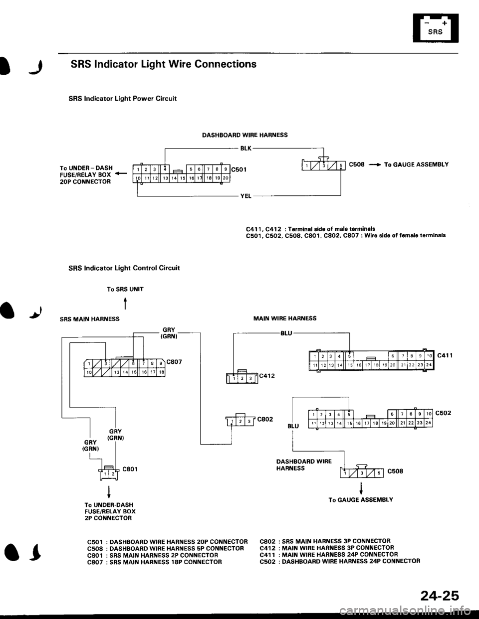
SRS Indicator Light Wire Connections
SRS Indicator Light Power Circuit
DASHBOARD WIRE HARNESS
To UNDER-DASHFUSE/RELAY BOX -
20P CONNECTOR
SRS Indicato. Light Control Circuit
To SRS UNIT
tI
SRS MAIN HARNESS
C41 1, C412 : Terminal sido of mdlo t6rminalsC501, C5O2, C508, C801. C802, C807 : Wi.6 sidc of fomalo t.rminals
MAIN WIBE HARNESS
BLU
C508 -+ To GAUGE ASSEMBLY
c41 1
To GAUGE ASSEMBLY
at
C501 : DASHBOARDWIRE HARNESS 2oP CONNECTORC508 : DASHBOARD wlRE HARNESS 5P CONNECTORC801 : SRS MAIN HARNESS 2P CONNECTORC807 : SRS MAIN HARNESS 18P CONNECTOR
C802 : SRS MAIN HARNESS 3P CONNECTORC412 : MAIN WIRE HARNESS 3P CONNECTORC41 1 : MAIN WIRE HARNESS 24P CONNECTORC502 : DASHBOARD WIRE HARNESS 24P CONNECTOR
GRY
OI
24-25
Page 1765 of 2189
)
From page 24-26
(A)
From page 24-26
(B)DASHBOARD WIRE HARNESS
5P CONNECTOR
It
MAIN WIRE HARNESS2,rP CONNECTOR
DASHAOARD WIREHARNESS 2irPCONNECTOR
c41 1
(cont'd)
24-27
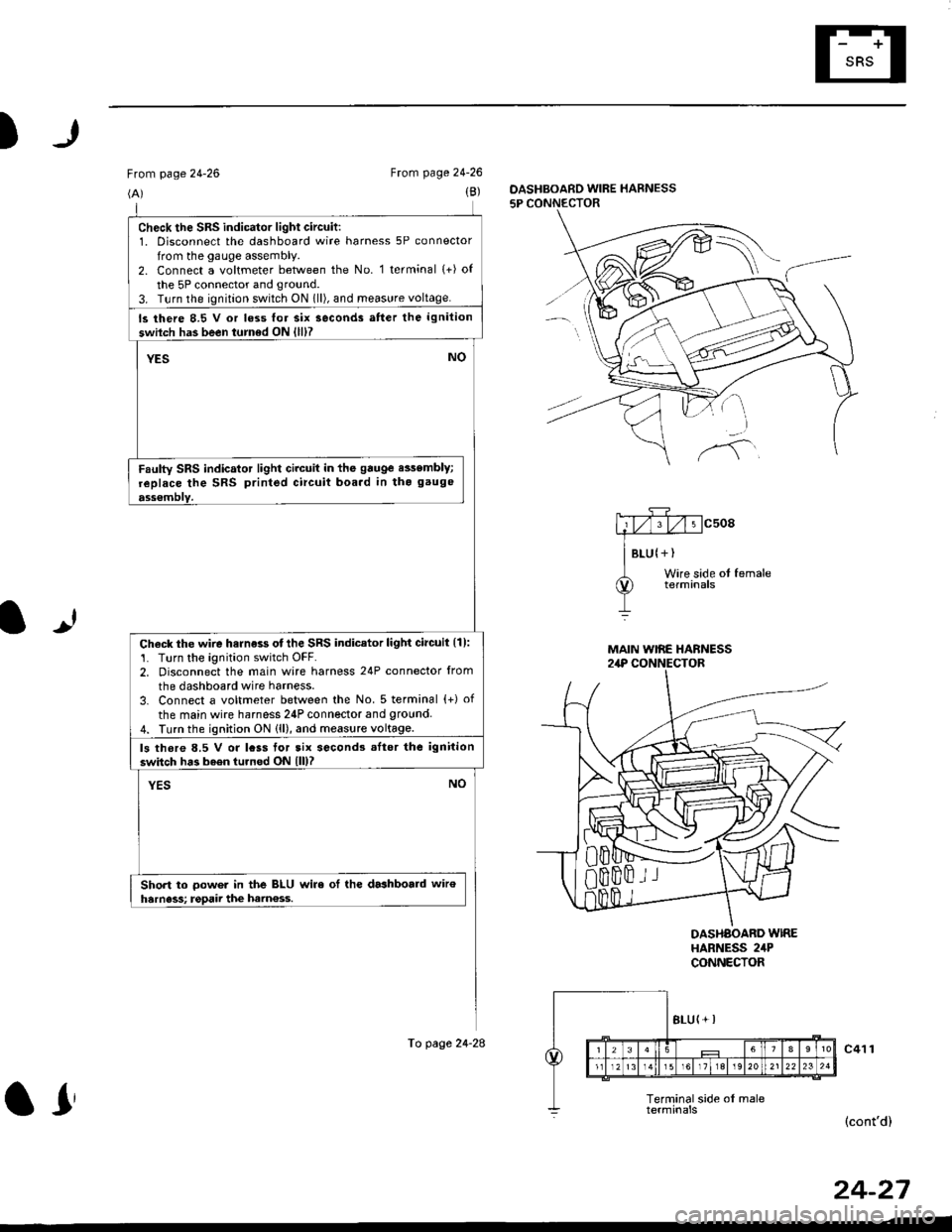
check the sRs indicator light circuit:1. Disconnect the dashboard wire harness 5P connector
from the gauge assembly.2. Connect a voltmeter between the No. 1 terminal (+) of
the 5P connector and ground.
3. T!rn the ignition switch ON 1ll), and meas!re voltage.
ls there 8.5 V or loss lor six seconds atter the ignition
swilch has been turned ON {lll?
YESNO
Faulty SRS indicator light circuit in the gauge e$embly;
replace the SRS printed circuit boa.d in tho gauge
ass€mblY.
Check the wire harness otthe SRS indicator light circuil {1):'1. Turn the ignition switch OFF.2. Disconnect the main wire harness 24P connector from
the dashboard wire harness.
3. Connect a voltmeter between the No. 5 terminal {+) of
the main wire harness 24P connector and 9round4. Turn the ignition ON (ll), and measure voltage.
ls thore 8.5 V or lcss tor tix second3 .Itor the ignition
switch has b6en turned ON lll)?
YESNO
Short to oower in the BLU wire ol the dashboald wiroharness; rgpaii the ham€ss.
To page 24-28
ar
Page 1769 of 2189
)
From page 24'30(B)
To page 24-33
5P CONNECTOF
mcsogA#
I Btu lYEtWire side of fomale
lUUpeA Wtng terminals
OASHBOARD WIRE HARNESS
It
Wire side ol femaletetmtnals
SRS MAIN HARNESSlAP CONNECTOR
(D)
To page 24'33
DASHBOARD WIRE HARNESS5P CONNECTOR
(cont'd)
DASHBOARD WINE HARNESS
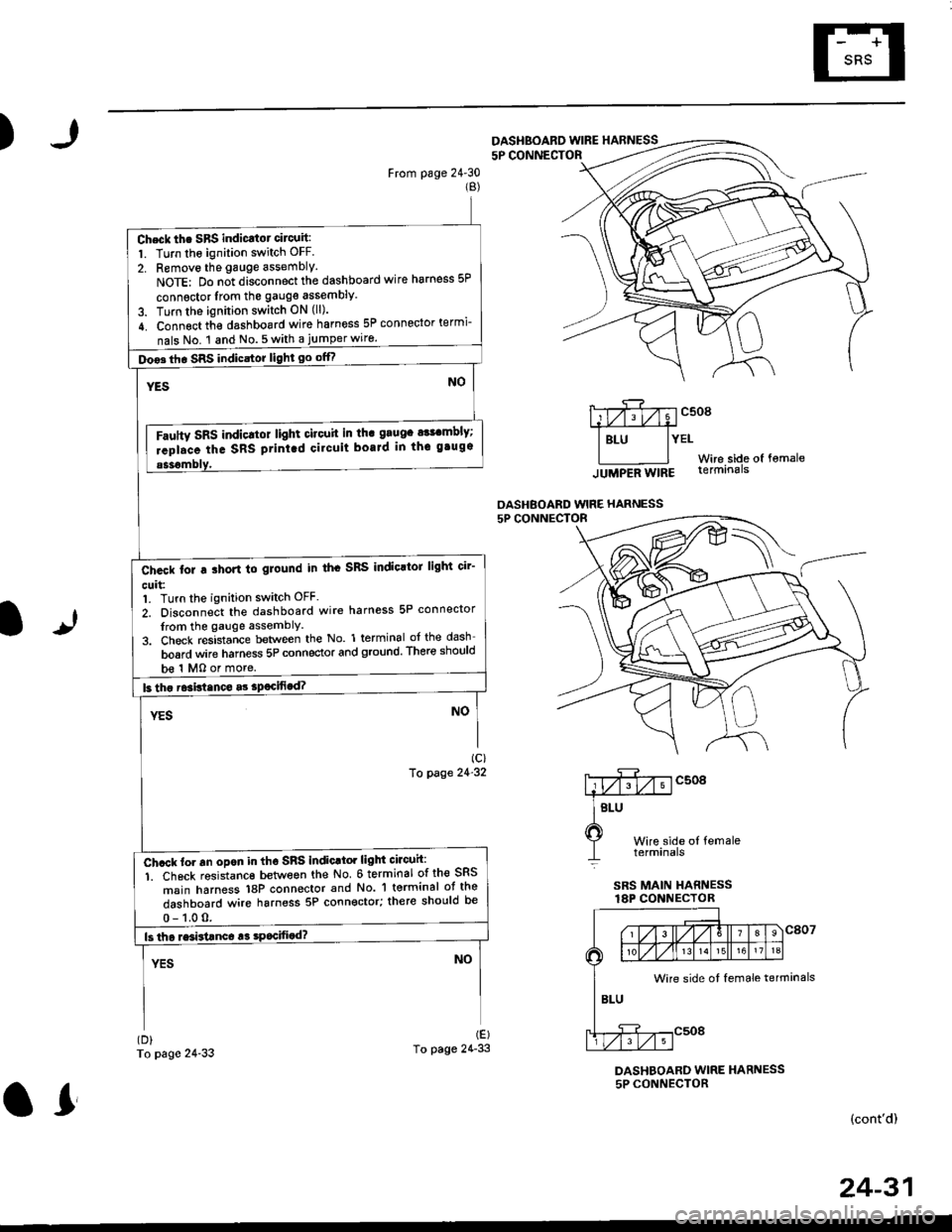
Check th. SBS indicatot circuit:
1. Turn the ignition switch OFF.
2. Removo the gauge assembly.
NoTE: Do n;t disconnect the dashboard wire harness 5P
connsctor lrom the gauge assembly
3. Turn the ignition switch ON (ll).
4. Connect th€ dashboard wire harness 5P connector termi-
nals No. 1 and No.5with a jumperwiro.
Doo3th. SRS indicstor light go offf
Fautty SRS indicltot light citouit in th. grugc a$cmbly;
rcpl.ce the SRS ptint.d cilcuit boaJd in thc gtugs
b€ 1 MO or more.
Ch.ck tor a ihort to glound in th. SRS IndioltoJ light cir'
cuit:1. Turn the ignition switch OFF.
2. Disconnect the dashboard wire harness 5P connector
from the gauge assemblY
3. Check resistance between the No. 1 terminal of the dash
board wire harness 5P connector and ground. There should
Ch.ck to. an opon in tho SnS indic.tor light circuh:
1. Ch6ck resistanc€ between the No 6 terminal of the SRS
msin harness 18P connector and No. 'l terminal ot the
dashboard wire harness 5P connector; there should be
Wire side ot female terminals
24-31
or
Page 1770 of 2189
Troubleshooting
The SRS Indicator Light Doesn't Go Off -'96 - 97 Models (cont'dl
From page 24-31
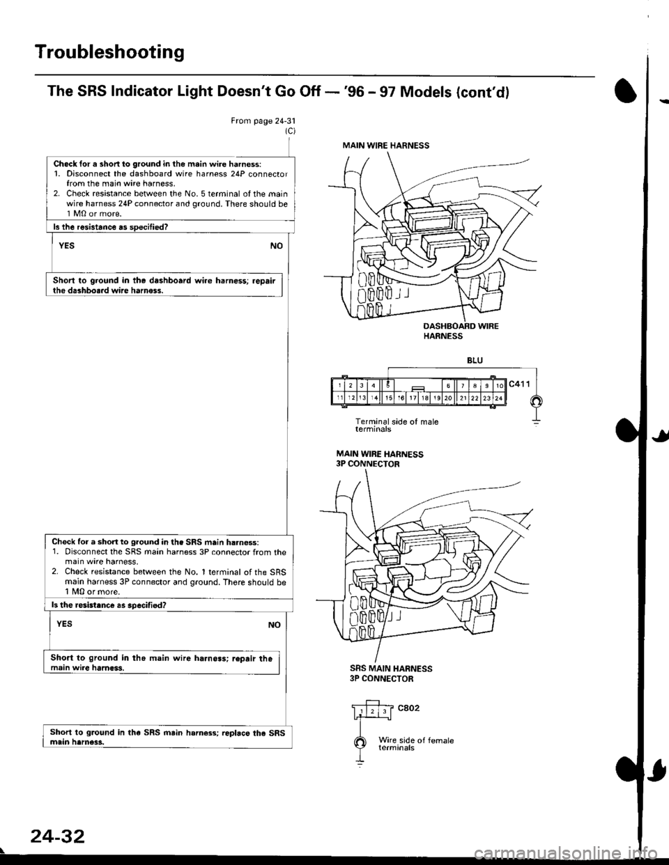
Ch6ck for a shon lo ground in tho m.in wire harness:1. Disconnect the dashboard wire harness 24P connectorfrom the main wire harness,2. Check resistance between the No. 5 terminal of the mainwire harness 24P connector and ground. There should be1 M0 or more.
Short to ground in the dashboard wire harness; repairthe dashbo..d wire harnoss.
SRS MAIN HARNESS3P CONNECTOR
Wire side oI femaleterminals
24-32
\
MAIN WIRE HARNESS
HARNESS
Check for a short to ground in the SRS main h..ness:1. Disconnect the SRS main harness 3P connector from themain wire harness,2. Check resistance between the No. 1 terminal of the SRSmain harness 3P connector and ground. There shorrld be1 fu,|0 or more.
ls the resistance as specifisd?
Short to ground in the main wire harnoas; r€pair themain wire harness.
Page 1773 of 2189
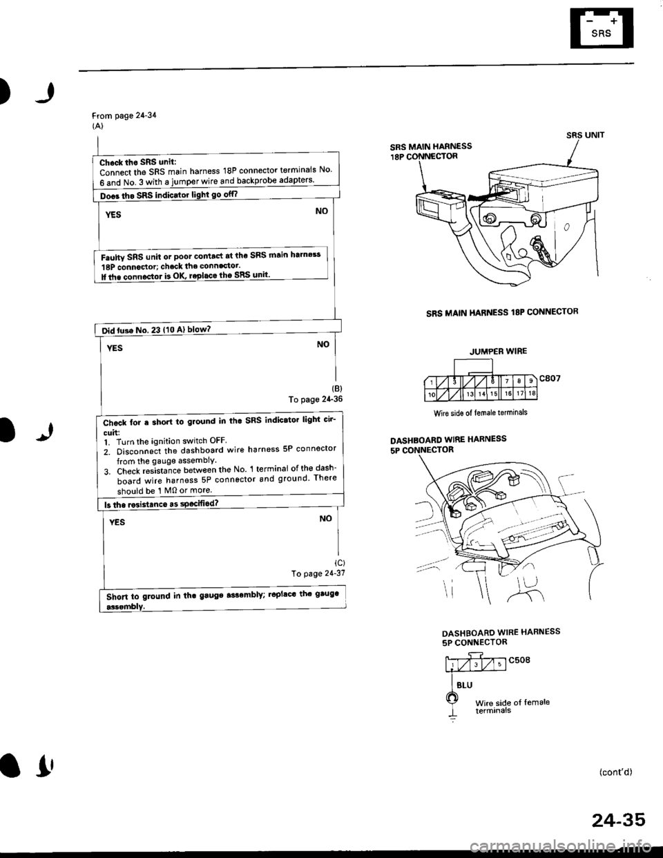
)
From page 24-34(A)
SRS MAIN HARNESS I8P CONNECTOR
(B)
To page 24-36
1)
Wire sidg of lemale terminals
DASHBOARD WIRE HARNESS
5P CONNECTOR
ic)To page 21'31
DASHBOARD WIRE HARNESS
5P CONNECTOR
c508
t of lemale
(cont'd)
24-35
SRS MAIN HARNESS
Chock iho SRS unit:
Connect the SRS main harness 18P connector terminals No'
6 and No. 3 with a jumper wire and backprobe
Doos tho SRS indicator light go off?
Faulw SRS unit or poot co tact at the SRS ftain htmes!
18P connoctor; chack the connagtot.
ll tha connoctor b OK roplaca lho SRS unit'
oid tu3e No. 23 t10 A) blow?
Chcck for e short to ground in th. SRS indicator lighi cir-
cuh:1. Turn the ignition switch OFF
2. Disconneit the dashboard wire harness 5P connector
from the gauge assembly.
3. Check res-ista;ce between the No l terminai ofth€dash-
board wire harness 5P connector and ground There
should be '1 M0 or more.
Short to glound in th. gaugs aslomblY; .6plac' th' gtug'
JUMPEB WIRE
o!
Page 1774 of 2189
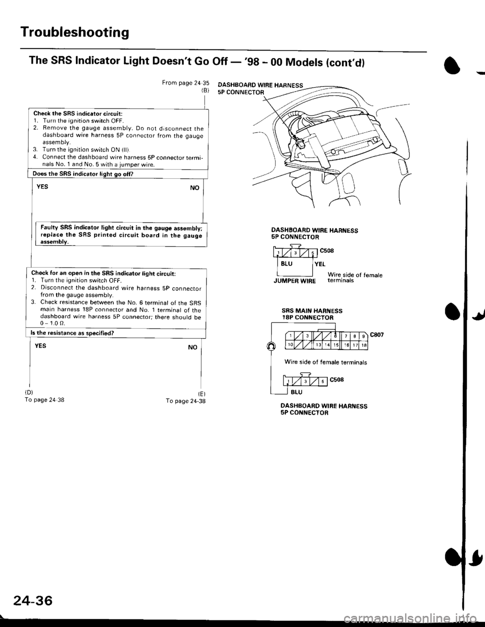
Troubleshooting
The SRS Indicator Light Doesn't Go Off - '98 - 00 Models (cont,dl
From page 24 351B)
Check the SRS indicetor circuit:1. Turn the ignition switch OFF.2. Bemove the gauge assembly, Do not dlsconnect thedashboard wire harness 5P connector from the gaugeassemoly.3. Turn the ignition switch ON (ll)4. Connect the dashboard wire harness 5P connector termi-nals No. 1 and No. 5 with a jumper wire.
Does the SRS indicator light go om
YESNO
Faulty SRS indicator light circuit in the 9au96 assembly;replace the SRS printed circuit board in the gaugeessembly.
Check for an open in the SRS indicator light circuit:r. rurn rne rqnrton swrtch ut-t-.2. Disconnect the dashboard wire harness 5p connectorfrom the gauge assembly.3. Check resistance between the No. 6 terminal of the SBSmain harness 18P connector and No. I terminal of thedashboard wire harness 5P connector; there should be0 1.0 0.
ls the resistance as soecified?
NOYES
(D)
To page 24 38(E)To page 24-38DASHBOARD WIRE HARNESS5P CONNECTOR
OASHBOARD WIRE HAR'{ESS5P CONNECTOR
llTf;rv;1c508.1#
I Bru lYErWire side of femaleJUMpER WIRE rerminats
SRS MAIN HARi{ESSI8P CONNECTOR
c807
24-36
DASHBOAED WIRE HARNESS
Wire side of female terminals
Page 1776 of 2189
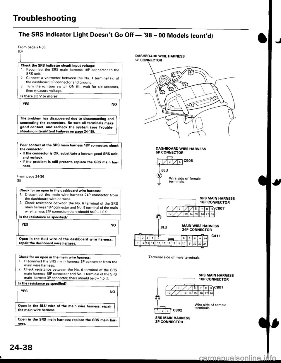
Troubleshooting
The SRS Indicator Light Doesn't Go Off -'98 - 00 Models (cont'dl
From page 24 36(D)
Check the SRS indicetor circuit input voltage:1. Reconnect the SRS main harness l8P connector to theSRS unit.2. Connect a voltmeter between the No. 1 terminal (+) ofthe dashboard 5P connector and ground.3. Turn the ignition switch ON (ll), wait for six seconds,then measure voltage,
ls th€re 8.5 V or more?
YESNO
The problem has disapp€ared due to di3connecting andconneding the connectors. Be su.e all te.minals makegood contact, and recheck the system {see T.ouble-shooting Inte.miftent Failures on page 24-15).
Poor contact et the SRS main harnass 18p connactori checkthe connector,. ll the connector is OK, substitute a known-good SRS unit,and recheck.' It the problem is still present, replace the SRS main haFness.
From page 24-36
Check for an open in the dashboard wir6 harness:1. Disconnect the main wire harness 24P connector fromthe dashboard wire harness.2. Check resistance between the No. 6 terminal of the SRSmain harness 18P connector and No. 5 terminal of the mainwire harness 24P connector; there should be 0 - 1.0 0.
ls the resistance as 3pecitied?
YESNO
Open in the BLU wire ot the dashboard wire harness;repair the dashboard wire harness.
Check tor an open in the main wire haanoss:1. Disconnect the SRS main harness 3P connector from themain wire harness.2. Check resistance between the No. 6 termanal of the SRSmain harness 18P connector and No. 1 terminal of the SRSmain harness 3P connector; there sho!ld be O - l.O 0.
ls the resistance a! specified?
YESNO
Open in the BLU wire of the m.in wire ha.ness: .eoairthe main wire harness.
Open in the SFS main hrrness; replace the SRS main har-ness.
DASHBOARD WIRE HARNESS5P CONNECTOR
c508
Terminal side of male lerminals
SRS MAIN HARNESS18P CONNECTOR
c807
c41 l
SRS MAIN HARNESS18P CONNECTOR
cao2
SRS MAIN HARNESS3P CONNECTOR
24-38
\
DASHBOARD WIRE HARNESS
Page 1780 of 2189
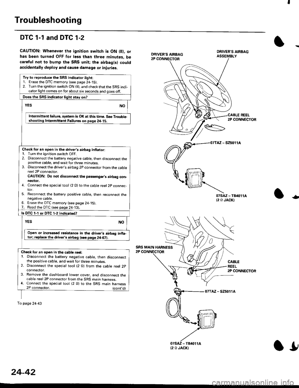
Troubleshooting
DTC 1-1 and DTG 1-2
CAUTION: Whenever the ignition switch is ON 0l), orhas been turned OFF for le33 than three minutes, becareful not to bump the SRS unit; the airbagls) couldaccidentally deploy and cause damage or inluries.
REEL2P CONNECTOR
AZ - SZ5011A
07sAz-TB{0t1At2 0 JACKT-
CABLEREEL2P CONNECTOR
07TAz - SZ5011A
DRIVER'S AIRBAG
SRS MAIN HARNESS
Try to reproduc€ the SRS indicator light:1. Erase the DTC memory lsee page 24,'15).2. Turn the ignition switch ON {ll), and check that the SRS indi-cator light comes on lor about six seconds and goes off.
Does the SRS indicator liqht 3tav on?
Intermittent lailure. system is OK at this time. So€ TloubleIntermittent Failur6 on Deqe 24-15.
Check for en open in th€ driver's airbag inllator:1. Turn the ignition switch OFF.2. Disconnect the battery negative cable, then disconnect thepositive cable, and wait for three minutes.3. Disconnect the driver's airbag 2P connector from the cablereel 2P connector.CAUTION: Do not disconnect the pa9,!eng6.,s ailbag con-nector.4. Connect the special tool {2 0)to the cable reel 2P connec,tor.5. Reconnect the battery positive cable, then reconnect thenegative cable,6. Erase the DTC memory {see page 24 15}.7. Read the DTC {see paqe 24-13).
ls OTC 1-1 or DTC 1-2 indicatod?
Open or incroas€d resistanc€ in the driver's ai.bag inoa-tor; r€place the d ve/s airbag lse6 pege 24€?).
Check for an opgn in the cabl6 reel:1. Disconnect the battery negative cable, then disconnectthe positive cable, and wait for three minutes.2. Disconnect the special tool {2 O) from the cable reel 2pconnector,3. Remove the dashboard lower cover, and disconnect thecable reel 2P connector from the SRS main harness.4. Connect the special tool {2 0} to the SRS main harness2P connector, {cont,
To page 24-43
(2 0 JACK)
24-42
l!
Page 1782 of 2189
Troubleshooting
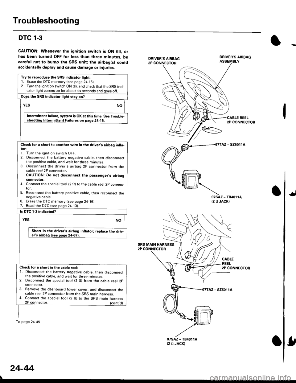
DTC 1-3
CAUTION: Whenever the ignition switch is ON {lll, orhas been turned OFF lor less than thrEe minutes, becaroful not to bump the SRS unit; the airbag(s) couldaccidenlally deploy and cause damage 01 iniuries.
DRIVER'S AIRBAGASSEMALY
REEL2P CONNECTOR
AZ - SZ5011A
07saz - TB4011A{2 0 JACK)
CABLEREEL2P CONNECTOR
07TAZ - SZ5011A
TrV to reproduce the SRS indicator light:1. Erase the DTC memory (see page 24-15).2. Turn the ignition switch ON (ll), and check that the SRS indicator light comes on for about six seconds and goes off.
Does the SRS indicalor light stav on?
YESNO
Intermittent lailure. system is OK ai this tim€. Se€ Troubl€-shooting Intermittent Failures on page 24-15.
Check tor a short lo another wire in the drivo.'s eirbrg in{la-
1. Turn the ignition switch OFF.2. Disconnect the battery negative cable, then disconnectthe positive cable, and wait for three minutes.3. Disconnect the driver's airbag 2P connector from thecable reel 2P connector,CAUTION: Do not disconnect the passenger's airb.gconnector,4. Connect the special tool (2 0)to the cable reel 2P connector,5. Reconnect the baftery positive cable, then reconnect thenegative cable,6. Erase the DTC memory (see page 24 15).7. Read the DTC (see page 24-13).
ls DTC 1-3 indicated?
NOYES
Shon in the driver's airbag intlator; replace the driv-er's airbag {see page 24-67}.
Check lor a short in the ceble reel:1. Disconnect the battery negative cable, then disconnectthe positive cable, and wait for three minutes.2. Disconnect the special tool (2 O) from the cable reel 2p
3. Remove the dashboard lower cover, and disconnect thecable reel 2P connector from the SRS marn naroess.4. Connect the special tool (2 O) to the SRS main harness2P coonector. {cont,di
fo page24-45
SRS MAIN HARNESS
24-44
07sAz - TBr011At2 0 JACKI
Page 1784 of 2189
Troubleshooting
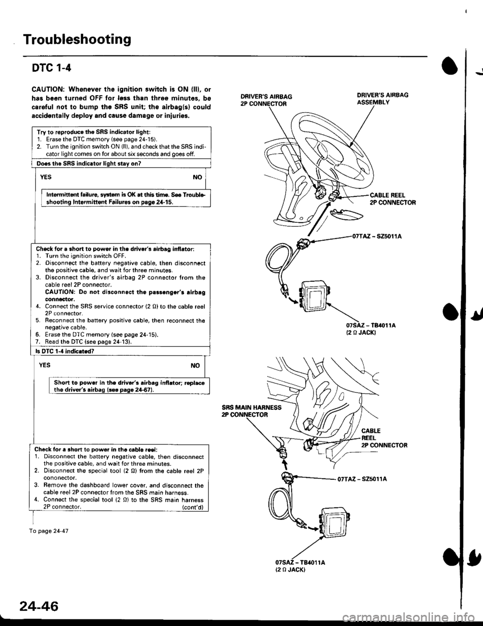
!DTC 1-4
CAUTION: Whenever ths ignition 3wiich is ON {lll, or
has boen turned OFF tor loss than three minutes, bs
caroful not to bump the SRS unit; the airbagls) could
accidoDtally deploy and cause damage or iniulies.
07SAZ - TB,()11A(2 0 JACKI
CABLEREEL2P CONNECTOR
07TAZ - Szsol'�lA
24-46
DRIVER'S AIRBAG
CABLE REEL2P CONNECTOR
Try to roproduc. the SRS indic.lor lightr1. Erase the DTC memory (see page 24-15).2. Turn the ignition switch ON (ll), and check that the SRS indi-cator light comes on tor about six seconds and goes off.
Ooes th6 SRS indicltor liqht stey on?
YESNO
Intermitid{ failure, 3y3tem b OK at this time. S€e Troublo-shooting Intormittont Failurss on pago 24.15.
Check for a 3hort to powo. in the d.iver's .irbag inflator:1. Turn the ignition switch OFF.2. Disconnect the baftery negative cable, then disconnectthe positive cable, and wait for three minut6s.3. Disconnect the driver's airbag 2P connector from thecable reel 2P connector.CAUTION: Do not disconnoct the parsengcr'r airbagconnactoa.4. Connect the SRS service connector (2 O) to the cable reel2P connector.5. Reconnect the battery positive cable, then reconnect thenegative cable.6. Erasethe DTC memory (see page 24-15).7. Read th6 DTC {seo page 24-13},
ls OTC 1-4 indic.tedT
YESNO
Short to pow.r in the driver'i rirbrg inilrtor; r€pl.cothe driver'! airbag l!e. paga 24-67).
Check for a ahort to Dow€r in tha crblo.eet:1. Disconnect the battery negative cabl€, then disconnectthe positive cable, and wait for three mrnur€s.2. Disconnect the special tool (2 O) trom the cable reel 2Pcononector.3. Bemove the dashboard lower cover, and disconnect thecable reel 2P connector trom th€ SRS main harness.4. Connect the special tool 12 0) to the SRS main harness2P connector. (cont'd)
fo page 24-47
SRS MAIN HABNESS
t2 0 JACK)