Fuel injector HONDA CIVIC 1998 6.G Owner's Manual
[x] Cancel search | Manufacturer: HONDA, Model Year: 1998, Model line: CIVIC, Model: HONDA CIVIC 1998 6.GPages: 2189, PDF Size: 69.39 MB
Page 433 of 2189
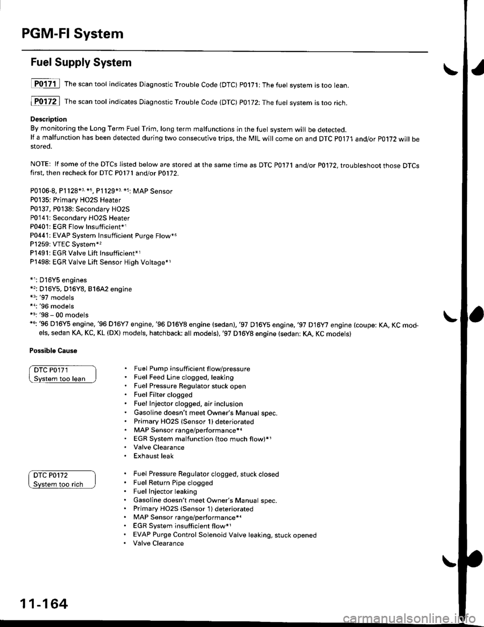
PGM-FI System
Fuel Supply System
D017-il Th""""ntool indicates Diagnostic Troubte Code {DTC) p0171;Thefuet system istoo lean.
1P0172 | fne scan tool indicates Dlagnostic Trouble Code (DTC) P0172:Thefuel system istoo rich.
Description
By monitoring the Long Term Fuel Trim, long term malfunctions in the fuel system will be detected.lf a malfunction has been detected during two consecutive trips, the MIL will come on and DTC P0171 and/or P0172 will bestored.
NOTE: lf some of the DTCS listed below are stored at the same time as DTC P0171 andlot P0172, ltouhleshoot those DTCSfirst. then recheck for DTC P0l7l andlot P0172.
P0106-8, P1128*3. *5, P1129*3 *5 MAP Sensor
P0135; Primary HO2S Heater
P0137. P0138: Secondary HO2S
P0'141: Secondary HO2S Heater
P0401: EGR Flow Insufficient*1
P0441: EVAP System Insufficient Purge Flow*6
P1259: VTEC System*,
P1491:EGR Valve Lift Insufficient*r
P1498: EGR Valve Lift Sensor Hjgh Voltage*r
*r: D16Y5 engines*'�: Dl6Y5, D16Y8, 81642 engine*3: '97 models*a:'96 modelsf 5: '98 - 00 models*6: '96 D16Y5 engine,'96 D16Y7 engine,'96 D16Y8 engine (sedan),'97 D16y5 engine,,97 D16y7 engine (coupe: KA, KC mo+els, sedan KA. KC, KL (DX) models. hatchback; all models),'97 D16Y8 engine (sedan: KA, KC models)
Possible Cause
DTC P0'171
loo lean
DTC P0172
too rach
Fuel Pump insuff icient f lovpressure
Fuel Feed Line clogged, leaking
Fuel Pressure Regulator stuck open
Fuel Filter clogged
Fuel Injector clogged, air inclusion
Gasoline doesn't meet Owner's Manual spec.
Primary HO2S (Sensor 1) deteriorated
MAP Sensor range/performance*.
EGR System malfunction (too much flow)*1
Valve Clearance
Exhaust leak
Fuel Pressure Regulator clogged, stuck closed
Fuel Return Pipe clogged
Fuel Injector leaking
Gasoline doesn't meet Owner's Manual spec.Primary HO2S (Sensor 1) deteriorated
MAP Sensor range/performance*a
EGR System insufficient flow*1
EVAP Purge Control Solenoid Valve leaking, stuck opened
Valve Clearance
11-164
Page 436 of 2189
I
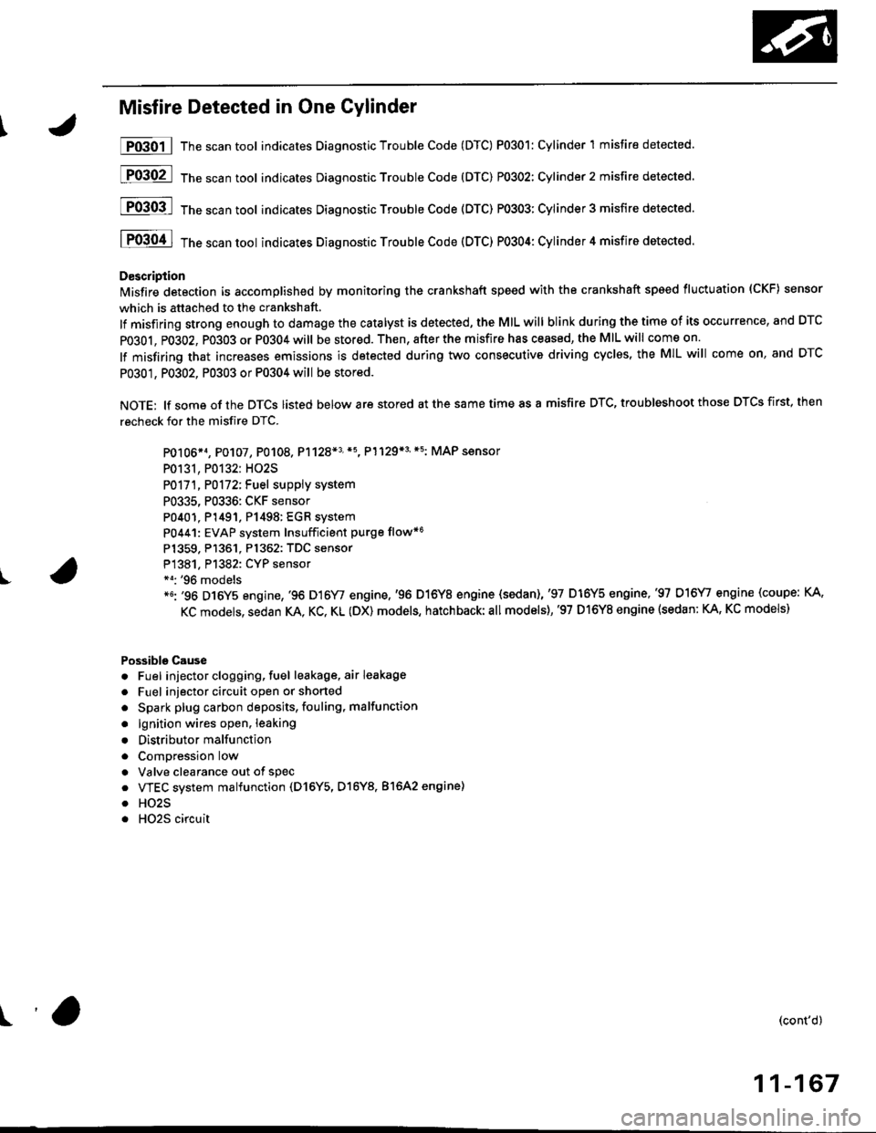
Misfire Detected in One Cylinder
P0301 | The scan tool indicates Diagnostic Trouble Code (DTC) P0301: Cylinder 1 misfire detected.
[F03O2l 16"""untool indicates Diagnostic Trouble code (DTc) P0302: Cylinder2 misfire detected.
[FO3Ofl 16" ".un toot indicates Diagnostic Troubte Code (DTC) P0303; Cylinder 3 misfire detected.
I P0304 I ths..rr tool indicates Diagnostic Trouble Code (DTC) PO3O4: Cylinder 4 misfire detected.
D€scription
lMisfire detection is accomplished by monitoring the crankshaft speed with the crankshaft speed fluctuation (CKF) sensor
which is attached to the crankshaft,
lf misfiring strong enough to damage the catalyst is detected, the MIL will blink during the time of its occurrence, and DTC
PO3O1, P0302, PO3O3 or P0304 will be stored. Then, after the misfire has ceased, the MIL will come on.
lf misfiring that increases emissions is detected during two consecutive driving cyclss, the MIL will come on, and DTC
P0301, P0302, P0303 or P0304 will be stored.
NOTE: lf some of the DTCS listed below are stored at the same time as a misfire DTC, troubleshoot those DTCS first, then
recheck for the misfire DTC.
PO106*1, P0107, P0108. P1128*3'*5, P1129*3'*5: MAP sensor
P0131, P0132: HO2S
P0171, P0172iFuel suppiy system
P0335, P0336: CKF sensor
P0401. P1491, P1498: EGR system
P0441: EVAP system Insufficient purge flow*6
Pl359. P1361. Pl362: TDC sensor
P1381. Pl382: CYP sensor*o: '96 models*6: '96 D16Y5 engine,'96 D16Y/ engine,'96 D16Y8 engine {sedan),'97 D16Y5 engine,'97 D16\4, engine (coupe: KA,
KC models, sedan KA. KC, KL (DX) models, hatchback:all models),'97 D16Y8 engine (sedan: KA, KC models)
Possible Cause
. Fuel injector clogging, fuel leakage, air leakage
. Fuel injector circuit open or shorted
. Spark plug carbon deposits, fouling, malfunction
. lgnition wires open. leaking
. Distributor malfunction
. ComDression low
. Valve clearance out of spec
. VTEC system malfunction (D16Y5, D16Y8. 81642 engine)
. HO2S
. HO2S circuit
(cont'd)
11-167
r'a
Page 437 of 2189
PGM-FI System
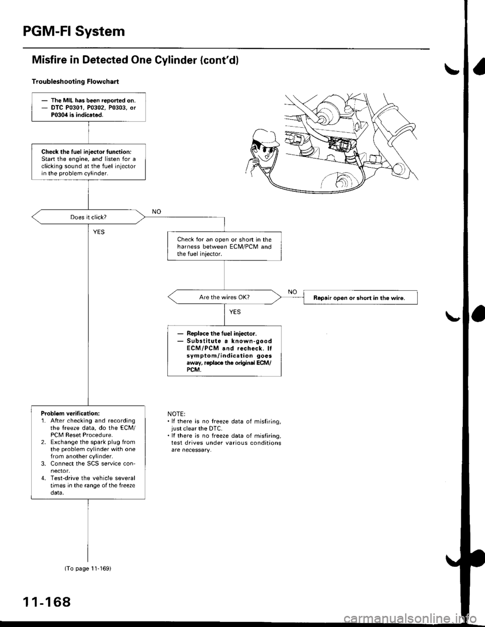
Misfire in Detected One Gylinder (cont'dl
Troubleshootin g Flowchart
NOTE:. lf there is no treeze data of misfiring,just clear the DTC.. It there is no freeze data of misfiring,test drives under various conditions
- The MIL has been reoorted on.- DTC P0301. P0302. P0303, orP030il is indicated.
Check the fuel iniecto. lunction:Stan the engine, and listen for aclicking sound at the fuel injectorin the problem cylinder.
Check for an open or short in theharness between ECM/PCM andthe fuel iniector.
Repair open or short in the wir€.
Replace the fuel iniector.Sub3titute a known-goodECM/PCM and recheck. Itsymptom/indication goesaway, replace the original ECM/PCM.
Problem verification:1. After checking and recordingthe freeze data, do the ECM/PCM Reset Procedure.2. Exchange the spark plug fromthe problem cylinder with onefrom another cylinder,3. Connect the SCS service con'nector,4. Test-drive the vehicle severaltimes in the range ofthe free2edata.
(To page 11-169)
1 1-1 68
Page 438 of 2189
I
ll
t
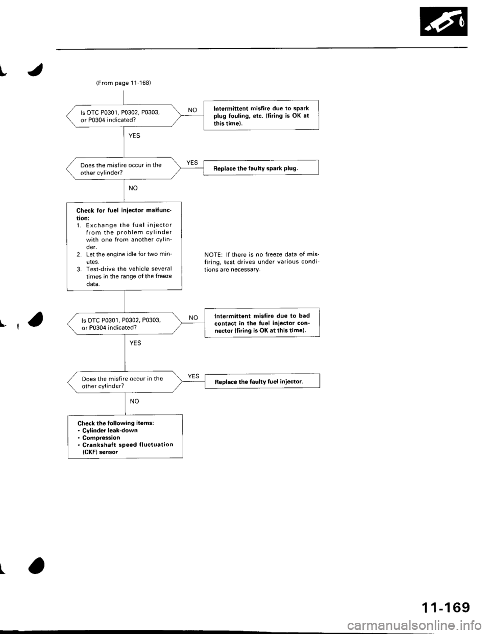
NOTE: lf there is no freeze data of mis_
firing, test drives under various condi
tions are necessary.
(From page 11'168)
Intermittent misfire due to sparkplug fouling, etc. (firing is OK arthis time).
ls DTC P0301, P0302, P0303,or P0304 indicated?
Does the misfire occur in theother cylinder?Replace the faulty spark plug.
Check for fuel iniector mallunc-
l|on:1. Exchange the fLrel injectorfrom the problem cylinderwith one from another cylinder.2. Let the engine idle for trrvo min-
utes.3. Test-drive the vehicle severaltimes in the range ot the freeze
data.
lntermitt€nt mistire due to badcontact in the fuel iniector con-nector (firing is OK at this time).
ls DTC P0301, P0302, P0303,or P0304 indicated?
Does the mistire occur in theother cylinder?Replace the taulty fuel injector.
Check lhe following items:. Cylinder leak-down. Compression. Crankshatt speod tluctuation
{CKF) sensoi
1 1-1 69
Page 499 of 2189
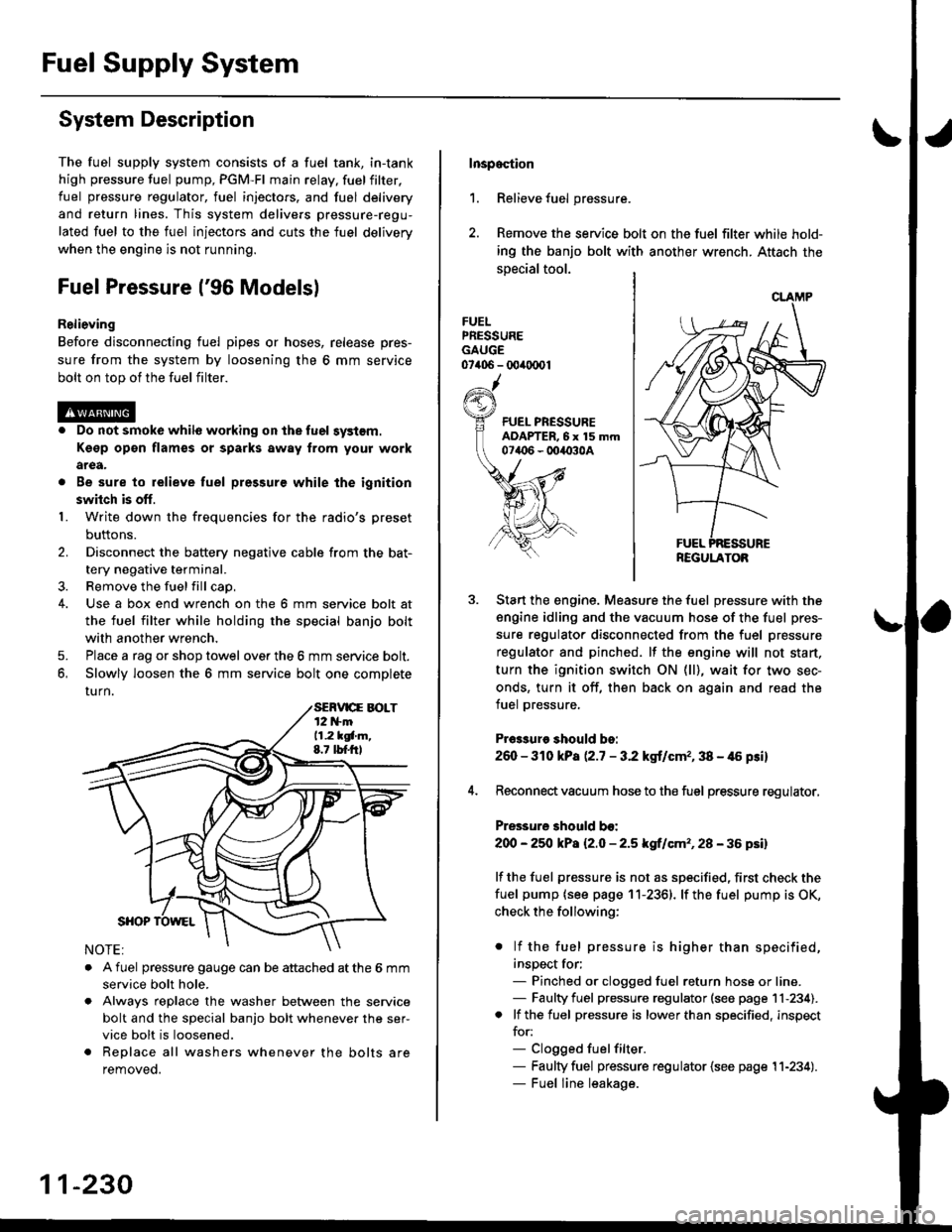
Fuel Supply System
System Description
The fuel supply system consists of a fuel tank, in-tank
high pressure fuel pump, PGM-FI main relay, fuelfilter,
fuel pressure regulator, fuel injectors. and fuel delivery
and return lines. This system delivers pressure-regu-
lated fuel to the fuel injectors and cuts the fuel delivery
when the engine is not running.
Fuel Pressure l'96 Modelsl
Relieving
Before disconnecting fuel pipes or hoses, release pres-
sure from the system by loosening the 6 mm service
bolt on top of the fuel filter.
. Do not smoke whil6 working on the fuel system.
Kgsp opon flames or sparks away from youl work
area.
. Be sure to relieve fuel pressure while the ignition
switch is off.
1. Write down the frequencies for the radio's preset
buttons.
2. Disconnect the battery negative cable from the bat-
tery negative terminal.
3. Remove the fuelfill cap,
4. Use a box end wrench on the 6 mm service bolt at
the fuel filter while holding the special banjo bolt
with another wrench,
5. Place a rag or shop towel over the 6 mm service bolt.
6, Slowly loosen the 6 mm service bolt one complete
rurn.
. A fuel pressure gauge can be attached at the 6 mm
service bolt hole.
. Always reDlace the washer between the service
bolt and the special banjo bolt whenever the ser-
vice bolt is loosened.
. Replace all washers whenever the bolts are
removeo.
11-230
Inspoction
1. Relieve fuel pressure.
2. Remove the service bolt on the fuel filter while hold-
ing the banjo bolt with another wrench. Attach the
special tool.
FUELPRESSUREGAUGE07406 - 00ir0(x)1
Start the engine. Measure the fuel pressure with the
engine idling and the vacuum hose of the fuel pres-
sure regulator disconnected from the fuel pressure
regulator and pinched. lf the engine will not start,
turn the ignition switch ON (ll), wait for two sec-
onds, turn it off, then back on again and read the
fuel pressure.
Pr€3sure should bo:
260 - 310 kPa (2.7 - 3.2 kgt/cmr, 38 - 46 psi)
Reconnect vacuum hose to the fuel pressure regulator,
Pressure should bo:
200 - 25O kPa l2.O - 2.5 kgf/cm'�, 28 - 36 psil
lf the fuel pressure is not as specified, first check the
fuel pump {see page 11-2361. lf the fuel pump is OK,
check the following:
. lf the fuel pressure is higher than specified,
inspect for;- Pinched or clogged fuel return hose or line.- Faulty fuel pressure regulator (see page 11-234).. lf the fuel pressure is lower than specified, inspect
for:- Clogged fuelfilter.- Faulty fuel pressure regulator {see page 11-234).- Fuel line leakage.
REGULATOB
Page 501 of 2189
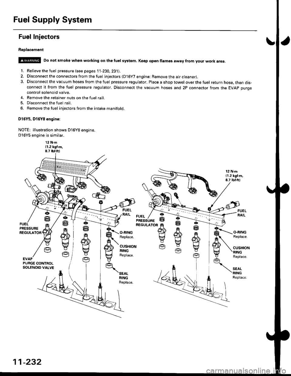
Fuel Supply System
Fuel Injectors
Replacement
@ Do not smoke when working on the tuel systgm, Keep gp6n flames away from your work area
'f. Relieve the fuel pressure (see pages 11-230,231J.
2. Disconnect the connectors from thefuel injectors (D16Y7 engine: Remove the air cleaner).
3. Disconnect the vacuum hoses from thefuel pressure regulator. Placeashoptowel overthefuel return hose, then dis-connect it from the fuel pressure regulator. Disconnect the vacuum hoses and 2P connector from the EVAp purgecontrol solenoid valve.
4. Remove the retainer nuts on the fuel rail.
5. Disconnect the fuel rail.
6. Removethefuel injectors from the intake manifold.
D16Y5, D16Y8 engine:
NOTE: lllustration shows D16Y8 engine.
D16Y5 engine is similar.
12 N.m11.2 kgl.m,8.7 rbt.ft)
12 N.m11.2 lgl.m,8.7 rbt.ftl
.q
wE4
Y
Ve
ffi}Yg
E
O.RINGReplace.
CUSHIONRINGReplace.
O.RINGReplace.
cusl{toNRINGReplace.
SEALRINGReplace.
ffi
E
EV
R
w
t
YEVAPPURGE CONTNOLSOLENOID VALVE
FUEL
11-232
Page 502 of 2189
\J
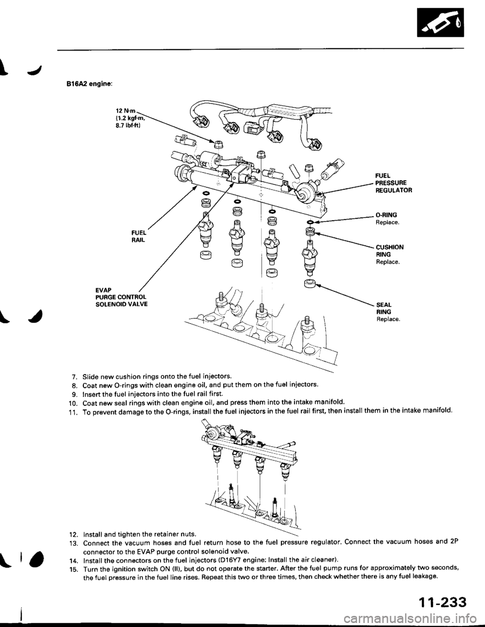
81642 engine:
EVAP
12 N.m
{1.2 kgl m;8.? lbt.ft)
FUELPRESSUREREGULATOR
O.RINGReplace.
cusHloNRINGReplace.
PURGE CONTROLSOLENOID VALVE
\
SEALRINGReplace.
7. Slide new cushion rings onto the fuel injectors.
8. Coat newO-ringswith clean engineoil, and putthem onthefuel injectors.
9. Insert the fuel injectors into the fuel rail first.
10. Coatnewseal rings with clean engine oil,and press them intothe intake manifold.
11. To prevent damage to the O-rings, installthe fuel injectors inthefuel rail first, then install them inthe intake manifold.
'12. Install and tighten the retainer nuts.
13. Connect the vacuum hoses and fuel return hose to the fuel pressure regulator, Connect the vacuum hoses and 2P
connector to the EVAP purge control solenoid valve.
14. Install the connectors on the fuel inl'ectors (D16YI engine; Install the air cleaner).
15. Turn the ignition switch ON (ll), butdo not operate the starter. After the tuel pump runs for approximately two seconds,
the fuel pressure in the fuel line rises. Repeat this two or three times, then check whether there is any fuel leakage.
11-233
Page 1486 of 2189

Connector ldentification and Wire Harness Routing
Engine Wire Harness lD16Y5, D16Y8 enginss): '96 - 98 models
Connector or
Torminal
Numbsr of
CavitissLocationConnects toNot€s
c 101c102c103c104c104c105c106c107c108c 109c110c111c112c113c114c115c116cl17c118c119c120cl21
c122c123cl23c124
c125
c127c12Ac129c130c131c132c 133c134c135
c136
c138c139c140c 141c142c 143c144cl44c145c'146cl47
10
1
22
14l4322l0I
2
2
2
2120
3l
14
14
1222
2
2
22
Left side of engine compartmentMiddle of engineMiddle of engineLeft side of engine companmentLeft side of engine compartmentMiddle of engineMiddle of engineMiddle of engineMiddle of engineMiddle of enginefvliddle of engineMiddle of engineMiddle of engineMiddle of engineMiddle of engineMiddle of engineMiddle of engineLeft side of engine compartmentMiddle of engineMiddle of engineMiddle of engineMiddle of engine
Middle of engineMiddle of engineMiddle of engineMiddle of engineMiddle of engineMiddle of engineMiddle of engineMiddle of engineMiddle of engineRight side of engine companmentBehind right kick panelUnder right side of dashUnder riOht side of dashUnder right side of dashUnder right side of dashUnder right side of dashUnder right side of dash
Under right side of dash
Under right side of dash
Middle of engineMiddle ot enginel iddle of engineMiddle of engineMiddle of ongineMiddle of engineLeft side of engine compartmentMiddle of engineMiddle of engineRight side of engine compartmentRight side of engine compartmentRight side of engine compartment
USACanada
Afi
USA
-' (A/r)
Main wire harness (C303)Crankshaft speed fluctuation (CKF) sensorEngine oil pressure switchAlternatorAlternatorNo. 'l fuel injectorNo. 2 fuel injectorNo.3 fuel injectorNo. 4 fuel injectorIAC valveThrottle position (TP) sensorl\4anifold absolute pressure (MAP) sensorIntake air temperature (lAT) sensorPower steering pressure {PSPI switchEVAP purge control solenoid valveJunction connectorJunction conn€ctorVehicle speed sensor {VSS}Countershaft speed sensorEngine coolant temp€rature (ECT) switch ADistributorEngine coolant temperature (ECT) sendingunrtEngine coolant temperature (ECT) sensorPrimary HO2S (sensor'l)Primary HO2S (sensor 1)Back-up light switchLock-up control solenoid valveSecondary HO2S (sensor 2)Mainshaft speed sensorLinear solgnoid valveShift control solsnoid valveStarter solenoidJunction connectorMain wire harnesE (C446)ECM/PCMPCMECMiPCMECM/PCMMain wire harness (C305)
Main wire harness (C305)
Main wire harness (C305)
Knock sensor (KS)IAC valveVTEC solenoid valveVTEC pressure switchEVAP control canister vent shut valveEGR control solenoid valveSecondary gear shaft speed sensorEGR valveEGR valveDrive pulley speed sensorSolenoid connector {CVT)Driven pulley speed sensor
*, (M/T)M/T*" INT\
*, tAtf)
NT:'96 model*,(A,/T):'97 - 98mooets
moqets
M/T
-1 (l,/T)*, (A,/T)-,(4,/T)*1 {M/T)*, (A,/T)*1 (CW)*, (A,T)
T101r102Left side of engine companmentRight side of engine companmentAlternatorUnder-hood fuse/relay boxG 101Middle of engineEngine ground, via engine wire harness
2
*1: Dl6Y5 engine*2: D16Y8 engine*3: D16Y5 (Ay'T), D16Y8 engines
3-16
Page 1488 of 2189
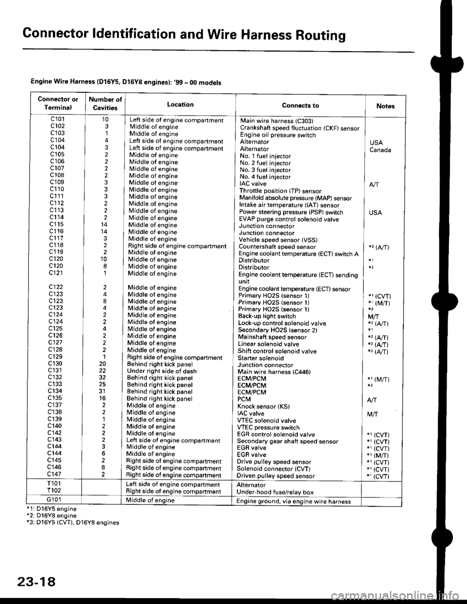
Gonnector ldentification and Wire Harness Routing
Engine Wire Harness (D16Y5, Dl6Yg engines): ,99 - 00 models
Connectot or
Terminal
Number ot
CavitiesLocationConn€cts toNotes
c'101cl02c103c104c 104c10s
c107c 108c'r09c110c111cl12c113cl14c l15c116cl17c118c119c120cl20c121
c122c123c123cl23cl24c124c125
c127c12Ac129c 130c131cl32c133c 134c135c137c138c 139c 140c142c143c144cl44c145c146c147
103,]
322223332221414322'10
8,l
2484224222120
32
2212223
282
No. 1 luel injector INo.2 fuel injectorNo.3 fuel injector ]No. 4 fuel injector iIAC valve I anThrottle position lTP) sensorManifold absolute pressure {MAP) sensor IIntake air temperature (lAT) sensor IPower steering pressure (PSP)switch USAEVAP purge control solenoid valve ]
Main wire harness 1C303)Crankshaft speed fluctuation (CKF) sensorEngine oil pressure switchAlternatorAlternator
Left side ot engine compartmentlvliddle of engineMiddle of engineLeft side ot engine compartmentLeft side of engine compartmentMiddle of engineMiddle ot engineMiddle of engineMiddle of engineMiddle oI engineMiddle of engineMiddle of engineMiddle of engineMiddle of engineNliddle of engineMiddle of engineMiddle of engineMiddle of engineRight side of engine compartmentMiddle of engineMiddle of engineN4iddle of engineMiddle of engine
Middle of engineMiddle ot engineMiddle ot engineMiddlo of engineMiddle of engineMiddle ot enginelrliddle of engineMiddle of engineMiddle oI engineMiddle ot engineRight side of engine compartmenlBehind right kick panelUnder right side of dashBehind right kick panelBehind right kick panelBehind righr kick panelBehind right kick panelMiddle ot engine[,liddle of engineN4iddle of engineMiddle of engineMiddle oI engineLeft side of engine compartmentMiddle of engineMiddle of engineRight side ol engine compartmentRight side of engine companmentRight side of engine compartment
USACanada
Junction connectorJUnct|On COnnectorVehicle speed sensor lVSS)Countershaft speed sensorEngine coolant temperature {ECT} switch ADistributorDistributorEngine coolant temperature (ECT) sendingunitEngine coolant temperature (ECT) sensorPrimary H02S (sensor 1)Primary HO2S (sensor 1)Primary HO2S lsensor 1)Back-up light switchLock'!p control solenoid valveSecondary HO2S (sensor 2)Mainshaft speed sensorLinear solenoid valveShift control solenoid valveStarter solenoidJunction connectorMain wire harness (C446)ECM/PCMECM/PCMECM/PCMPCtvtKnock sensor (KS)IAC valveVTEC solenoid valveVTEC pressure switchEGR control solenoid valveSecondary gear shaft speed sensorEGR valveEGR valveDrive pulley speed sensorSolenoid connector (CVT)Driven pulley speed sensor
*'� (A/TI
*1 (CVT)*, (M/T)
Mfia (A/Tl
" (A,/T)., (4,/r)-'� {AlrJ
*1 (M/T)
tvliT
*1 (CVT)*, (cvT)*' (cw)*1 (MiT)*1 {CVT)*1 {CVT)*, (cvr)
T101T102Left side of engine companmentRight side ot engine companmentAlternatorUnder'hood fuse/relay boxG 101Middle of englne IEngine ground, via engine wire harness*1: 016Y5*2: D16Y8*3: Dl6Y5
engineengine(CW), D16Y8 engines
23-14
Page 1490 of 2189
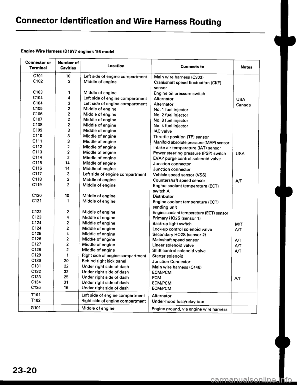
Gonnector ldentification and Wire Harness Routing
Engine Wire Harness {D16Y7 engine}: '96 model
Conneclor or
Terminal
Number ot
CavhiesLocationConnects toNotes
c101
c102
c 103
c104
c104
c105
c'r06
c107
c 108
c 109
c110
c111
c112
c l13
c't14
LttS
cl16
cl17
c118
cl19
c120
c121
c123
c124
c124
c125
c126
c't27
c12a
c129
c130
c131
c132
c133
c134
c135
10
1
4
5
'14
14
10
1
,,
2
2
1
22
31
16
No. 1 fuel injector INo. 2 fuel injector
No. 3 fuel injector INo,4 fuel injector
IAC valve l
Throttle position (TP)sensor IManifold absolute pressure (MAP) sensorIntake ai. temperature (lAT) sensor ]Power steering pressure (PSP) switch I USAEVAP purge control solenoid valve IJunction connector
Junction connector IVehicle speed sensor (VSS) |Countershaft speed sensor AlTEngine coolant temperature (ECT) I
Main wire harness (C303)
Crankshaft speed fluctuation (CKF)
sensor
Engine oil pressure switch
Alternator
Alternator
switch A
Distributor
Engine coolant temperature (ECT)
sending unit
Engine coolant temperature lECT) sensor
Primary H02S (sensor 1)
Back-up light switch
Lock-up control solenoid valve
Secondary HO2S (sensor 2)
Mainshaft speed sensor
Linear solenoid valve
Shift control solenoid valve
Staner solenoid
Junction Connector
Main wire harness {C446)ECM/PCM
PCM
ECM/PCM
ECM/PCM
Left side of engine compartment
Middle of engine
Middle of engine
Left side of engine compartment
Left side of engine compartment
Middle of engine
Middle of engine
Middle of engine
Middle of engine
Middle of engine
Middle of engine
Middle of engine
Middle of engine
Middle of engine
Middle of engine
Middle of engine
Middle of engine
Left side of engine compartment
Middle of engine
Middle of engine
Middle of engine
Middle of engine
Middle of engine
Middle of engine
Middle of engine
Middle of engine
Middle of engine
Middle of engine
Middle of engine
Middle of engine
Right side of engine compartment
Behind right kick panel
Under right side of dash
Under right side of dash
Under right side of dash
Under right side of dash
Under right side of dash
USA
Canada
M/T
AtJ
Afi
T101
T102
Left side of engine compartment
Right side of engine compartment
Alternator
Under-hood fuse/relay box
G101Middle of engineEngine ground, via engine wire harness
23-20