PC box HONDA CIVIC 1998 6.G Owner's Manual
[x] Cancel search | Manufacturer: HONDA, Model Year: 1998, Model line: CIVIC, Model: HONDA CIVIC 1998 6.GPages: 2189, PDF Size: 69.39 MB
Page 499 of 2189
Fuel Supply System
System Description
The fuel supply system consists of a fuel tank, in-tank
high pressure fuel pump, PGM-FI main relay, fuelfilter,
fuel pressure regulator, fuel injectors. and fuel delivery
and return lines. This system delivers pressure-regu-
lated fuel to the fuel injectors and cuts the fuel delivery
when the engine is not running.
Fuel Pressure l'96 Modelsl
Relieving
Before disconnecting fuel pipes or hoses, release pres-
sure from the system by loosening the 6 mm service
bolt on top of the fuel filter.
. Do not smoke whil6 working on the fuel system.
Kgsp opon flames or sparks away from youl work
area.
. Be sure to relieve fuel pressure while the ignition
switch is off.
1. Write down the frequencies for the radio's preset
buttons.
2. Disconnect the battery negative cable from the bat-
tery negative terminal.
3. Remove the fuelfill cap,
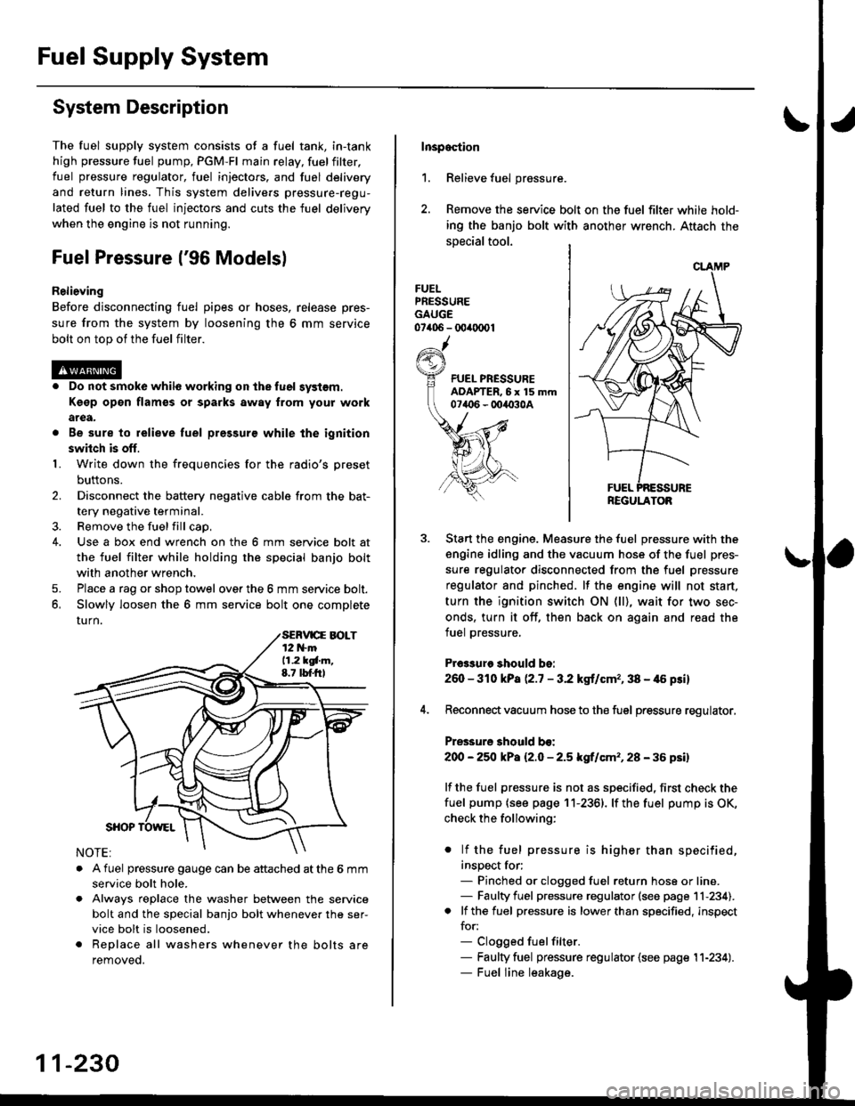
4. Use a box end wrench on the 6 mm service bolt at
the fuel filter while holding the special banjo bolt
with another wrench,
5. Place a rag or shop towel over the 6 mm service bolt.
6, Slowly loosen the 6 mm service bolt one complete
rurn.
. A fuel pressure gauge can be attached at the 6 mm
service bolt hole.
. Always reDlace the washer between the service
bolt and the special banjo bolt whenever the ser-
vice bolt is loosened.
. Replace all washers whenever the bolts are
removeo.
11-230
Inspoction
1. Relieve fuel pressure.
2. Remove the service bolt on the fuel filter while hold-
ing the banjo bolt with another wrench. Attach the
special tool.
FUELPRESSUREGAUGE07406 - 00ir0(x)1
Start the engine. Measure the fuel pressure with the
engine idling and the vacuum hose of the fuel pres-
sure regulator disconnected from the fuel pressure
regulator and pinched. lf the engine will not start,
turn the ignition switch ON (ll), wait for two sec-
onds, turn it off, then back on again and read the
fuel pressure.
Pr€3sure should bo:
260 - 310 kPa (2.7 - 3.2 kgt/cmr, 38 - 46 psi)
Reconnect vacuum hose to the fuel pressure regulator,
Pressure should bo:
200 - 25O kPa l2.O - 2.5 kgf/cm'�, 28 - 36 psil
lf the fuel pressure is not as specified, first check the
fuel pump {see page 11-2361. lf the fuel pump is OK,
check the following:
. lf the fuel pressure is higher than specified,
inspect for;- Pinched or clogged fuel return hose or line.- Faulty fuel pressure regulator (see page 11-234).. lf the fuel pressure is lower than specified, inspect
for:- Clogged fuelfilter.- Faulty fuel pressure regulator {see page 11-234).- Fuel line leakage.
REGULATOB
Page 500 of 2189
tJFuel Pressure {'97 and later Models)
ReliGving
Before disconnecting tuel pipes or hoses, release pres-
sure from the system by loosening the 12 mm banjo
bolt on top of the fuel filter.
@o Do not smoke whilo working on the fuel sy3lom.
Ksgp op€n flames or sparks away tlom Your work
arga.
. Be sure to relieve fuel pressule while the ignition
swhch is off.
1. Write down the frequencies for the radio's preset
buttons,
2. Disconnect the battery negative cable from the bat-
tery negative terminal.
3. Remove the fuel fill cap.
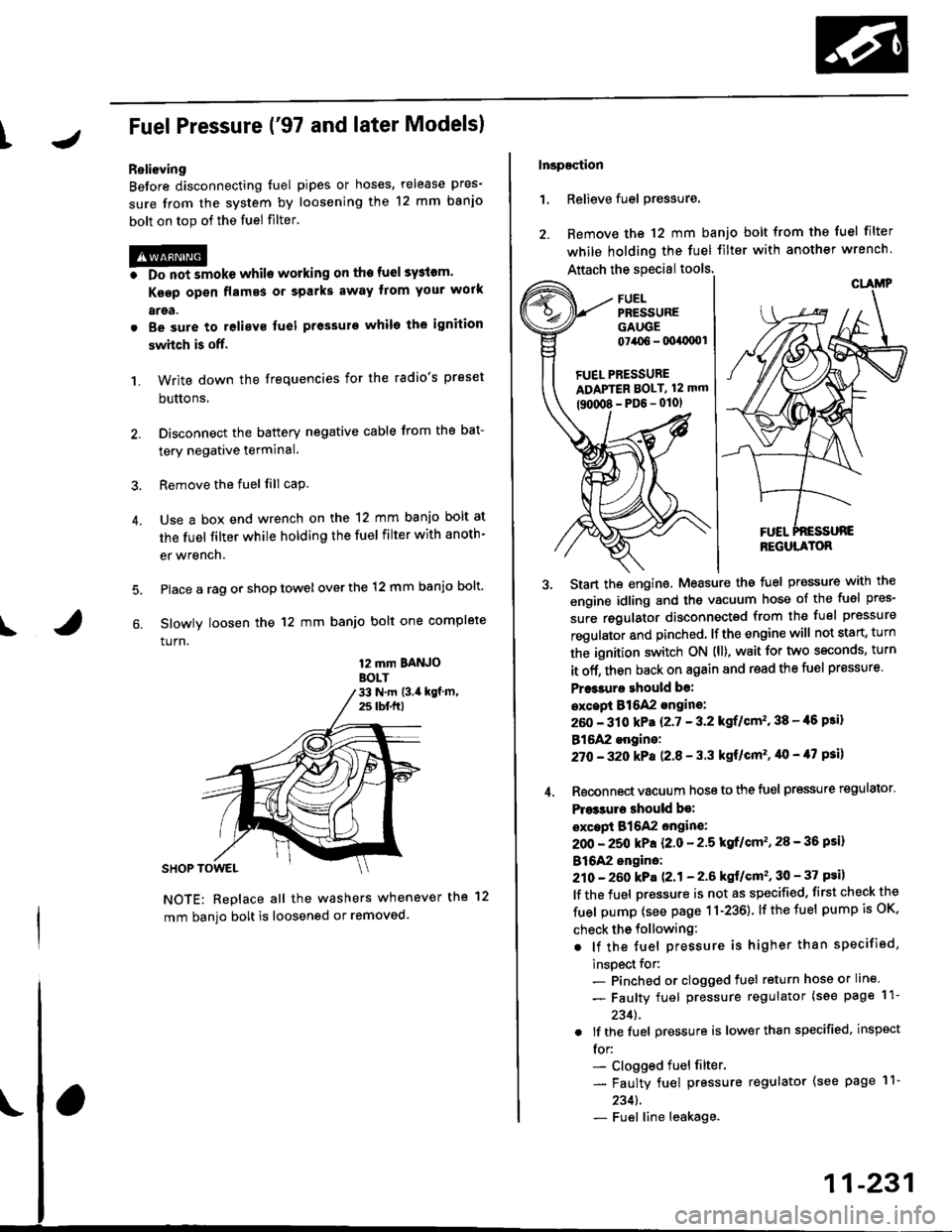
Use a box end wrench on the 12 mm banjo bolt at
the fuel filter while holding the fuel filter with anoth-
er wrench.
Place a rag or shop towel over the 12 mm banio bolt.
Slowly loosen the 12 mm banjo bolt one complete
turn.
4.
I
12 mm BAtt OBOLT33 N.m (3.i1 kgf m,25 tbf.f0
NOTE: Replace all the washers whenever the 12
mm banio bolt is loosened or removed.
Inspaqtion
1. Relieve fuel pressure.
2. Remove the 12 mm banjo bolt from the fuel filter
while holding the fuel Jilter with another wrench
Attach the special tools.
3. Start the enginethe fuel Pressure with the
engine idling and the vacuum hose of the fuel pres-
sure regulator disconnected from the fuel pressure
regulator and pinched lfthe engine will not start, turn
the ignition switch ON {ll), wait for two seconds, turn
it off, then back on again and read the fuel pressure'
Pr$3uro ehould be:
excepi 816A2 sngine:
260 - 310 kPa {2'7 - 3.2 kgf/cm" 38 - {6 Fi}
B16A2 engine:
27O -32O kPa P.8 - 3'3 kgf/cm'�, '10 - 47 psi)
4. Reconnect vacuum hoso to the fuel pressure regulator'
Pre33ure 3hould be:
except B16A2 engin€:
2OO - 250 kPa {2.0 - 2'5 kgf/cm'�, 28 - 36 psi)
B16A2 engino:
210 - 260 kPa 121 - 2.6 ksf/cm'�, 30 - 37 psi)
lf the fuel pressure is not as specified, first check the
fuel pump (see page 11-236) lfthetuel pumpisoK,
check tho following:
. lf the fuel pressure is higher than specified,
inspect for:- Pinched or clogged fuel return hose or line.
- Faulty fuel pressure regulator (see page 11-
2341.
. lf the fuel pressure is lower than specified, inspect
for:- Clogged fuel filter.
- Faulty fuel pressure regulator (see page l1-
2341.- Fuel line leakage.
FUEL PRESSUREADAPTER BOLT, 12 mm
tguxt8-PD6-0101
CLAMP
REGULATOR
11-231
Page 507 of 2189
Fuel Supply System
PGM-FI Main Relay (cont'dl
Circuit Troubleshootin g
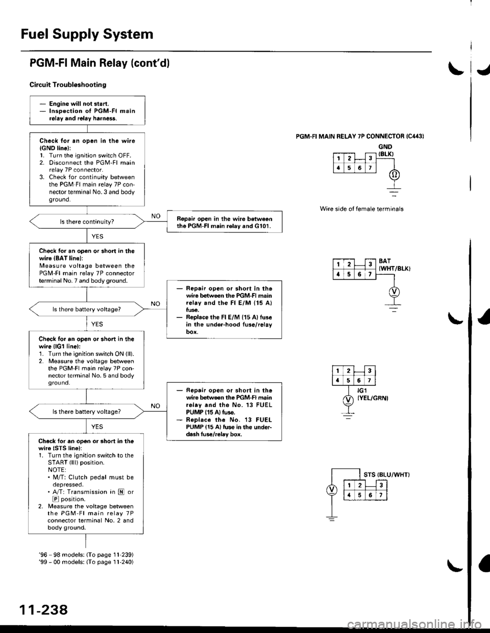
PGM.FI MAIN RELAY 7P CONNECTOR {C443)
GND{8LK)
Wire side of female terminals
/BLK}
- Engine will not start.- lnsoection of PGM-FI mainrelay and relay harne$.
Check for an open in the wire{GNO line}:l. Turn the ignition switch OFF.2. Disconnect the PGM-Fl mainrelay 7P connector.3. Check for continuity betweenthe PGM Fl main relay 7P con-nector terminal No.3 and bodyground.
Ropai. open in the wir€ betweenthe PGM-FI main .elav and G101.
Check for an open or short in thewire {BAT lin€}:N4easure voltage between thePGM-FI main relay 7P connectorterminal No. 7 and body ground.- Repair open or sho.t in thewire between the PGM-FI mainrelay and the Fl E/M {15 A}fus€.- Replace the Fl E/M (15 Allu3ein the under-hood fuse/relayoox.
ls lhere battery voltage?
Check tor an open or short in thewire {lGl line):1. Turn the ignition switch ON (ll).
2. Measure the voltage betweenthe PGM-Fl main relay 7P con'nector terminal No. 5 and bodyground.- Repair open or short in thewire betwoen the PGM-FI mainrelav and the No. 13 FUELPUMP (15 A)tuse.- R€place the No. 13 FUELPUMP {15 A} tus€ in the under-d.sh fus€/relay box.
ls there battery voltage?
Ch.ck for an open or short in thewire {STS lino}r1. Turn the ignition switch to theSTART (lll) position.NOTE:. M/T: Clutch pedal must beoepresseo.. A/T: Transmission in E or
E position.2, Measure the voltage betweenthe PGM-Fl main relay 7Pconnector terminal No, 2 andbody ground.
12
[,a567
123BAT
{WHTa56,
'96 98 models: (To page 1l 239)'99 - 00 models: (To page I l-240)
11-238,
Page 508 of 2189
JI
I
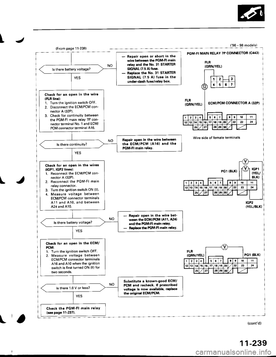
- Repair open or 3hort in the
wire bstw€er the lGM-Fl mainrolsy .nd the No. 31 STARTERSGNAL 17.5 A) tuse.- Reolace the No. 31 STARTER
SIGNAL (7.5 Al fu3o in the
unde.-dash tusg/rolav box.
ls there baftery voltage?
Chock lor !n open in the wit.
lFLn line)l1. Turn the ignition switch OFF
2. Disconnect the ECM/PCM con-
nector A (32P).
3. Check for continuity between
the PGM-FI main relay 7P con-
nectorterminal No. 1 and ECM/
PCM connector terminal A16.
Ropair op6n in th. walo betwoanthe ECM/PCM lA16) and thc
PGM-FI main rolaY.
Ch6ck for an opon in th. wi.e3
llcPl,lGP2linesl:1. Reconnect the ECM/PCN4 con-nector A (32P).
2. Reconnoct the PGM-Fl main
relay connector,3. Turn the ignition switch ON (ll)
4. Measure voltage between
ECM/PCM connector termanals
A11 and A10, and betweenA24 6nd A10.
Repeir opon in th6 wire bet-
ween ttre ECiA /PCM (A11, A24)
and tho PGM-FI msin r.lty.
R€plac. tho FGM-FI main rc|.Y.
Check tor an open in the ECM/
PCM:1. Turn the ignition switch OFF.
2, Measure voltage between
ECM/PCM connector terminalsA16 and A10 when the ignition
switch is lirst turned ON (ll) for
two seconds.
Substituta a known-good ECM/
PCM and rechcck. lf proacribod
voltege is now availablc, r.Placethe originll ECM/PCM.
ls thero 1.0 V or less?
Ch6ck th. PGM-FI m.in lolay(.ee pagc 11-2371.
('96 - 98 models)
t32Pt
Wire side of female terminals
IGP2{YEL/BLKI
FLRIGRN/YELIPGl
3l5 6 7l lslel tl1l
1213'tal5t6't7t8t920221 232a
2527284t
(cont'd)
1 1-239
IBLK)
{GRN/YELI
FLR(GRN/YELI
23
()a6t
ECM/PCM CONNECTOR A
21Il0t1
12r31'al5't61'tti9ml,/x2232a
25212e293ol./
PGl (BLK)
1I
12't/t15t617t8t9zi
25272A4t304l
Page 509 of 2189
Fuel Supply System
- Repair op€n or short in thewir€ betlveen the PGM-FI mainrelay and the No. 31 STARTERSIGNAL 17.5 A) fuse.- RoDlace the No. 31 STARTERSIGNAL {7,5 Al tuse in theunder-dash luse/rolay box.
ls there battery voltage?
Check tor an open in the wire(FLR linel:1. Turn the ignition switch OFF.2. Disconnect the ECM/PCM con-nector A (32P).
3. Check for continuity betweenthe PGM-FI main relay 7P con-nector terminal No. 1 and ECM/PCM connector terminal A16.
Repair open in the wir6 botweenthe ECM/PCM (A161 and rhePGM-FI main relay.
Check for an open in the wires{lGPl, lGP2 line3):1. Reconnect the ECM/PCM con-nector A {32P).2. Reconnect the PGM-Fl mainrelay connector.3. Turn the ignition switch ON (ll).
4. Measure voltage betweenECN4/PCM connector terminals81 and 820, and betweenBg and 820.
- Repair open in the wire bet-ween th. ECM/PCM (81, Bg)snd the PGM-F main rolay.- Roplace th€ PGM-FI main relav.
Chock tor an open in th6 ECM/PCM:1. Turn the ignition switch OFF.2. Measure vo ltage betweenECM/PCM connector terminalsA16 and 82 when the ignitionswitch is first turned ON lll) for
Sub3titute . known-good ECM/PCM and rochock. lf prescribedvohege is now available, replacethe original ECM/PCM.
ls there 1.0 V or less?
Chock the PGM-Fl m.in r6lay{see p.ge 11-2371.
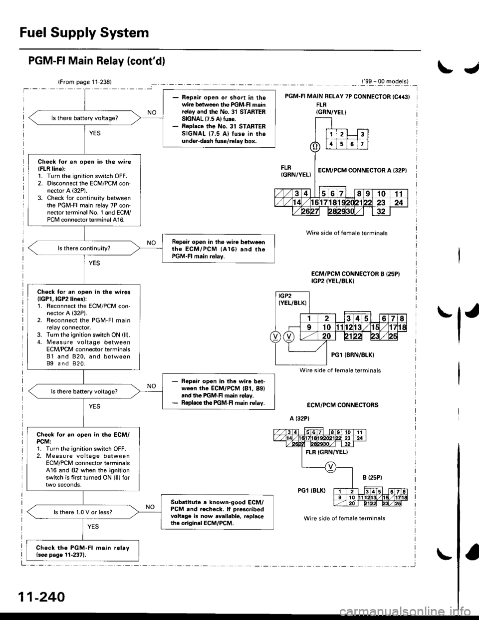
PGM-FI Main Relay (cont'd)
_._(9x . qq -gqerll _
PGM.FI MAIN FELAY 7P CONNECTOR {C4€}FLR
ECM/PCM CONNECTORS
A (32P1
Wire side ot female terminals
Wire side of fem6le terminals
ECM/PCM CONNECTOR B {25PIIGP2 {YEL/BLKI
IGRN/YEL}
IGP2(YEL/BLKI
Wire side of female terminals
11-240
IJ
'l'
Page 544 of 2189
\J
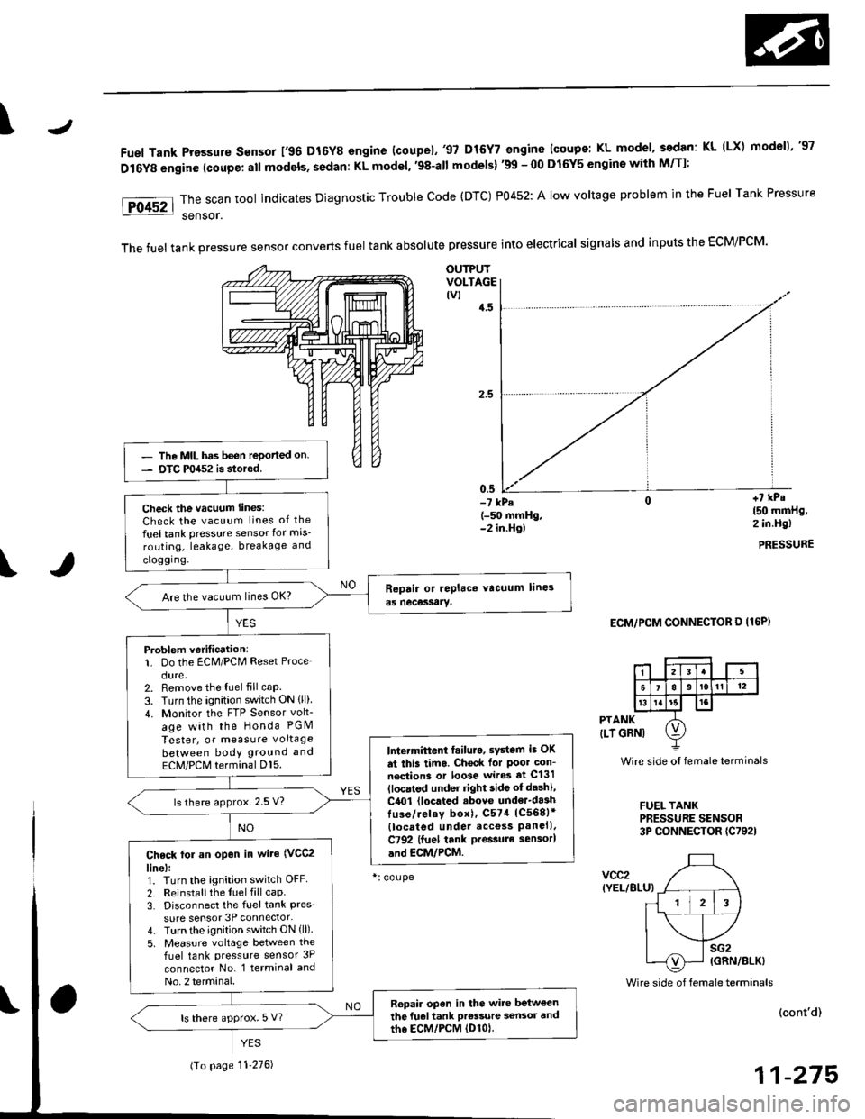
Fuel Tank Pro3sure sensor 196 D16Y8 engine (coupe).'97 D15Y7 engine {coupe: KL model, sedan: KL (LX) modeu,'97
D16Y8 engine (coupe: all models, sedan: KL model, '98-all models) '99 - 00 D16Y5 engine with M/Tl:
\
PTANK
{LT GRNI
vcc2(YEL/BLU}
Wire side oI female terminals
FUEL TANKPRESSURE SENSOR3P CONNECTOR (C7921
sG2IGRN/8LK)
Foc2l::il":"toolindicatesDiagnosticTroublecode(DTc)P0452:A|owvo|tageprob|emintheFue|TankPressure
The fuel tank pressure sensor converts fuel tank absolute pressure into electrical signals and inputs the EcM/PCM.
OUTPUTVOLTAGEtvt4.5
-? kPa(-50 mmHg,-2 in.Hg)
ECM/PCM CONNECTOR O I16P)
Wire side of female terminals
+7 kPs150 mmHg,2 in.Hg)
PRESSURE
(cont'd)
11-275
- The MIL has been reported on- DTC P0452 is stored.
Check the vacuum lines:
Check the vacuum lines of the
fuel tank pressure sensor for mis-
routing, leakage, breakage and
cloggrng.
Are the vacuum lines OK?
Problem v€ritication:1. Do the ECM/PCM Reset Proce
dure.2. Remove the luel fill caP.
3. Turn the ignition switch ON lll)4. Monitor the FTP Sensor volt_
age with the Honda PGM
Tester, or measure voltage
between bodY ground and
ECM/PCM terminal Dl5.lntermittent tailuro, sYstem i5 OK
dt this timo. Chock for Poot con-
neciion3 or loose wir* at C131
llocatod under right side ot dashl,
C4O1 (located .bove under'da3htuso/ielay box), C574 1C568)*
{located under acc€ss Panell.C792 lfuel tank pressule sen3or)
and EcM/PCM.
ls there approx. 2.5 V?
Check tol an op€n in wite (VCC2
line):1. Turn the ignition switch OFF
2. Reinstallthe fuel fill caP.3. Disconnect the fuel tank Pres'sure sensor 3P connector-4. Turn the ignition switch ON (ll)
5, Measure voltage between the
fuel tank pressure sensor 3P
connector No. l terminal and
No. 2 terminal.
Repair open in the wite betweenthe fuel tank Pr€s3ure a€n3or andth6 EcM/PcM (D1ol.ls there approx. 5 V?
(To page 11'276)
Page 546 of 2189
\
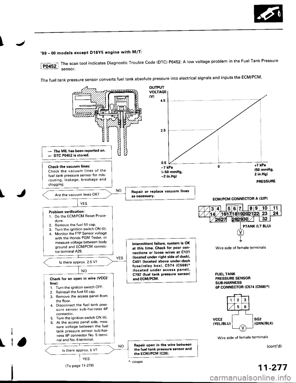
'99 - 00 models excepi Dl6Y5 engine with M/T:
The scan tool indicates Diagnostic Trouble Code (DTC) P0452: A low voltage problem in the Fuel Tank Pressure
sensor.
The fuel tank pressure sensor converts fuel tank absolute pressure into electrical signals and inputs the ECM/PCM
OUTPUTVOLTAGE(vlt.5
0.5-7 kP.(-g) mmHg,-2 in.Hgl
+7 kP.
150 mmHg,2 in.Hgl
PRESSURE
I
Wire side of lemale terminals
FUEL TANKPRESSURE SENSORSUB.HARNESS6P CONNECTOR (C574 (C568)rl
vcc2(YEL/BLUIsG2{GRN/BLK}
Wire side o{ temale terminals
The MIL has been .eported on.
DTC P0452 is stored
Check the vacuum lines:
Check the vacuum lines of the
fuel tank pressure sensor lor mis-
routing, leakage, breakage and
cloggrng.
Are the vacuum hnes OK?
Problem veritication:1. Do the ECM/PCM Reset Proce-
du re,2. Bemove the fuel fill caP.
3. Turn the ignition switch ON {ll)
4. Monitorthe FTP Sensor voltage
with the Honda PGM Tester' or
measure voltage between body
groLrnd and ECM/PCM connec_
tor terminalA29.
lntermitlent tailure, 3Ystem b OK
at this time. Check for Poor con'
nections or loose wire3 at C131
{located under right side of dash},
C401 {located above under'dash
tuse/relay box), C574 (C568)*
llocdted under access Panel),C792 (tuel rank Prcssure sensorl
and ECM/PCM.
ls there approx.2 5 V?
Check for an open in wire {VCC2
line):1. Turn the ignition switch OFF.
2. Reinstall the ltrel fill caP
3, Remove the access Panel from
the floor.4. Disconnect the fuel tank Pres'sure sensor sub-harness 6P
5. Turn the ignition switch ON (ll).
6. At the access Panel side, mea_
sure voltage between the fuel
tank Pressure sensor sub-nar-
ness 6P connector No 5termi
nal and No. 6 termlnal.
Repair open in tho wire between
th6 fu€l tank Prossuro sen3oa and
the ECM/PCM lc28).ls there approx 5 V?
ECM/PCM CONNECTOR A (32P)
PTANK {LT BLUI
I
ll
(To page '11-278)
(cont'd)
Page 548 of 2189
\
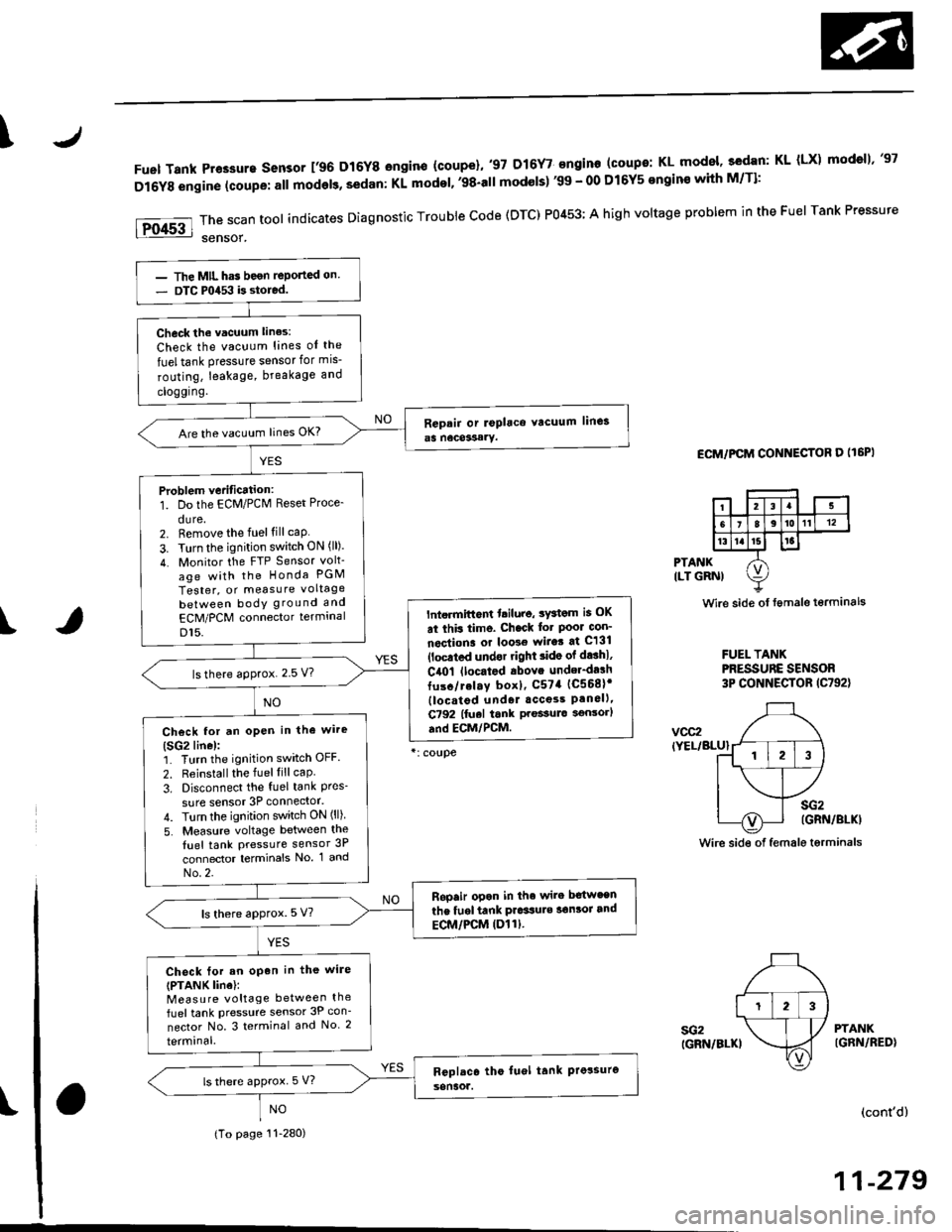
Fue| Tank Pr€ssure sensor 196 Dr6Y8 engine (coupe},,97 D16Y7 angino (coupo: KL mode|' 3edan: KL (Lxl modg||',97
Dl6Y8 engine (coupe: all modeb, sedan: Ki model.'98'all modols) 39 - 0O Dl6Y5 ongins with M/Tl:
rFoG'l::;Jl"too|indicatesDiagnosticTroub|ecode(oTc)P0453;Ahighvo|tageprob|emintheFue|TankPressure
ECM/PCM CONNECTOR D Il6PI
PTANKILT GRNI
\
Wire side of tgmale torminals
FUEL TANKPRESSURE SENSOR3P CONNECTOR (C792)
vcc2(YEL/BLU}
sG2(GRN/BLKI
Wire sid€ of female terminals
I
sG2IGRN/BLKI
PTANKIGBN/RED}
(cont'd)
11-279
The MIL has beon reponed on
DTC P0453 b stored.
Check the vacuum lines:
Check the vacuum lines oI the
fueltank pressure sensor for mis-
routing, leakage, breakage and
clogging.
Are the vacuum lines OK?
Problem verification:1. Do the ECM/PCM Reset Proce-
dure.2. Femove the fuel fill cap
3. Turn the ignition switch oN (ll).
4. Monitor the FTP Sensor volt-
age with the Honda PGM
Tester, or measure voltage
between bodY ground and
ECM/PCM connector termrnal
D15.
lntormittont t iluro, 3Ystem is OK
at this time. Check lot Poor con_
noctiona or loo3e wirat at C131
{loc.ted undor right 3id6 of d8hl,
CaOl llocatod rbov. under-dalh
fus6/relay boxl, C574 (C568lr
llocatod und6l accoss Pan6ll,C792 lfuel tank Preasulo aonlorl
end ECM/PCM.
ls there approx. 2 5 V?
Check for an oPen in the wire(SG2line):1. Turn the ignition switch OFF.
2. Reinstall the fuellill cap
3. Disconnect the fuel tank Pres-sure sensor 3P connector.
4. Turn the ignition switch ON (ll)
5. Measure voltage between the
fuel tank Pressure sensor 3P
connector terminals No. 1 and
No.2.
Ropair opon in the wira b€tw€sn
the fuel tank prasure sonlor and
ECM/PCM (Dl1).ls there aPProx. 5 V?
Check for an open in the wire(PTANK line):Measure voltage between the
fueltank Pressure sensor 3P con-
nector No. 3 terminal and No. 2
termrnal,
ls there approx. 5 V?
*: coupe
{To page 11-280)
Page 550 of 2189
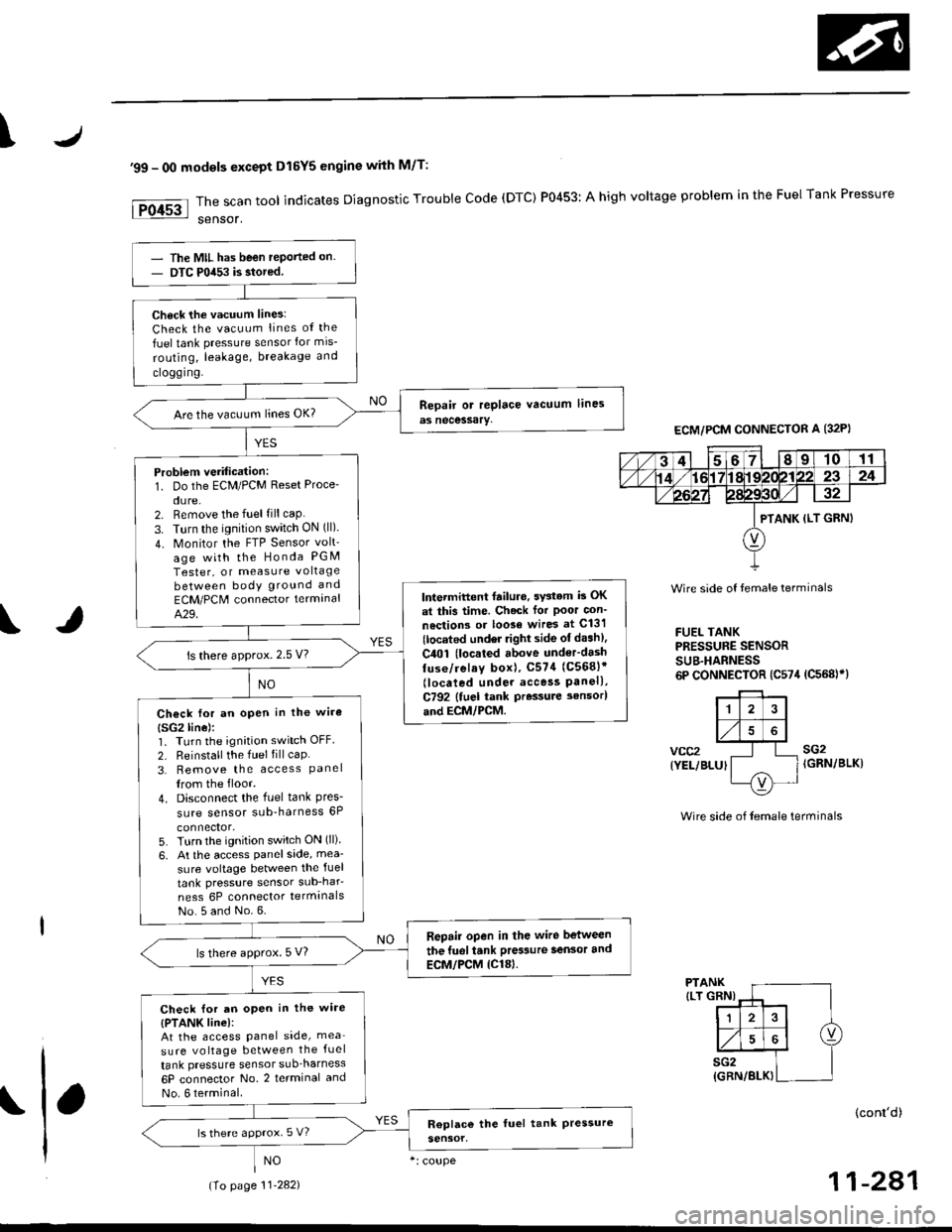
\
'99 - 0O modols except Dl5Y5 engine with M/T:
rFo45'::n":"tooIindicatesDiagnosticTroub|ecode(DTc)P0453:Ahighvo|tageprob|emintheFUelTankPressure
Wire side of temale terminals
FUEL TANKPRESSUNE SENSOR
SUB.HARNESS6P CONNECTOR {C574 (C568)}}
vcc2{YEL/BLUI
sG2IGRN/BLK)
Wire side of female terminals
PTANK{LT GRNI
(cont'd)
11-281
ECM/PCM CONNECTOR A {32P)
PTANK {LT GRN)
The MIL has been reported on.
DTC P0453 is stored.
Check the vacuum lines:
Check the vacuum lines ot the
fuel tank pressure sensor for mis-
routing, leakage, breakage and
clogging.
Are the vacuum lines OK?
Problem verilication:1. Do the ECM/PCM Reset Proce-
du re,2. Remove the fuel fill caP
3. Turn the ignition switch ON (ll).
4. Monitor the FTP Sensor volt'
age with the Honda PGM
Tester, or measure voltage
between body ground and
ECM/PCM connector terminalA.29.
lntermittent failuro. svstem b OK
at this time. Check for Poor con_
noctions or loo3€ wire3 at C131
{located under tight side of dash),
C4Ol {located above underdash
fuse/relay boxl, C57{ (C5681'
llocaled unde. access Panell,C792 {fuel tank Pressure sensorl
aod ECM/PCM.
ls there approx.2.5 V?
Ch€ck for an open in the wira
{SG2line):1. Turn the ignition switch OFF.
2. Reinstall the fuel fill caP
3. Remove the access Panellrom the floor.
4. Disconnect the fuel tank Pres-sure sensor sub-harness 6P
5. Turn the ignition switch ON (ll)
6, At the access Panelside, mea-
sure voltage between the fuel
tank pressure sensor sub_har-
ness 6P connector termlnals
No.5 and No.6.
Repair open in the wire between
the fueliank Pres3ure 3ensor and
ECM/PCM {Cl8).ls there approx.5 V?
Check lor an oPen in the wire
{PTANK linel:At the access Panel side, mea
sure voltage between the fuel
tank pressure sensor suo_harness
6P connector No. 2 terminal and
No. 6 terminal.
ls there approx. 5 V?
(To page 11.282)
Page 718 of 2189
![HONDA CIVIC 1998 6.G Owners Manual PGM Gircuit Diagram (A/T Control System: 96 - 98 Modelsl
UNDEfl -HOOD FUSE/RELAY BOX
No.41 (80A1 N0.42 l40A)
No.47 {7.5 A)
No.l3 (15A)
Arp Np lon,^o l r,, lotrr l 6lt l 3]t lot*
UNDER DASHFUSE/REIAY HONDA CIVIC 1998 6.G Owners Manual PGM Gircuit Diagram (A/T Control System: 96 - 98 Modelsl
UNDEfl -HOOD FUSE/RELAY BOX
No.41 (80A1 N0.42 l40A)
No.47 {7.5 A)
No.l3 (15A)
Arp Np lon,^o l r,, lotrr l 6lt l 3]t lot*
UNDER DASHFUSE/REIAY](/img/13/6068/w960_6068-717.png)
PGM Gircuit Diagram (A/T Control System: '96 - 98 Modelsl
UNDEfl -HOOD FUSE/RELAY BOX
No.41 (80A1 N0.42 l40A)
No.47 {7.5 A)
No.l3 (15A)
Arp Np lon,^o l r,, lotrr l 6lt l 3]t lot*
UNDER DASHFUSE/REIAY 8OX
/8LU
c10
YEUBLKBtK
424
Btx
At0423
'96:BLU/BED'97, '98r GFN/BLK
TTTYEL GRN BLULT GRN
BLK/BTU
RED
GRNiELK
F- BTK/BI.U
F_wHr
F- GRN
f- GRN
F- Bru
GRN
BLU
NorE: t :ro5v
T :ro 12v
GAUGE ASSEMBTY
A,T GEAR POSITIONINDICATOR
824 t88 tB17'96: GRN 8LU
'96: BLU/RED al'97,'98: GRN/8LK --