combination light switch HONDA CIVIC 1998 6.G Owner's Manual
[x] Cancel search | Manufacturer: HONDA, Model Year: 1998, Model line: CIVIC, Model: HONDA CIVIC 1998 6.GPages: 2189, PDF Size: 69.39 MB
Page 2053 of 2189
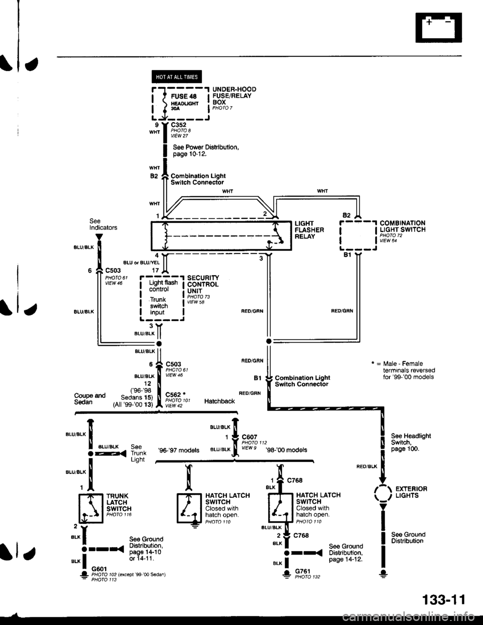
UNDER.HOODl t FUsE4s I FUSEiRELAY! xamucnr ! BoX
I I.A I PHoro 7
LJ,----Jc352
vtEw 27
Soe Pow€r Distdbulion,page 1&12,
Combination LightSwitch ConnectorE2
SeelndicatorsCOMBINATIONI I LIGHT SWITCH
| | v;iw; -
LIGHTFLASHERRELAY
4aLU or ALU/YEI
c503
iTFffiliBi+B,il:"'s#Ji"" I coNrRoL
i#$ iI input IL ----J3YBLU/BLK ll:aBrui 8rK ll
*,rlfr ftT-f.","
,^ftslllfl li^ir,, Ha,chback
vtEw 58
Coupa tndSedan
Combination LightSwitqh Connector
r = l\,lale - Femaletermrnals reversedlor'99-'00 models
See HeadlightSwiich,peg61(n.
EXTERIORLIGHTS
Seo GroundDistribution
"'u'"t*X
".u,"."aE,<
-*;"1
SeeTrunkLight
'9+ 97 models
aau,"a" fi
'*9#1",,,
BLU/BLKrf vEwe g8-,oo modets
l
qi*$qli-
TRUNKLATCHswrTcH
":^f se€ Ground
5--r< !#itl8".* I o"o'
or 14-11
.|- PHOIO ro2lorcoDr'99 oo sedan): PHofo 113
";-f "^'
FE
I-I-t HATCH LATCHI I I swtrcx
lljij::,:}#x""'*if
"tut
seecroundo tr
e.* | Page 14-12'
+ 9131",,,
133-11
Page 2108 of 2189
-
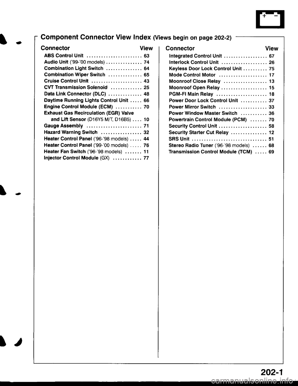
Component Connector View Index (Views begin on page 202-21
Connector View
ABS Control Unit........ ......63
Audio Unit ('99-'00 models) ......74
Combination Light Switch . . . . . . . . . . . . . . . 64
Combination Wiper Switch . . . . . . . . . . . . . . 65
Cruise Control Unit.... .....43
C\TTTransmission Solenoid ............. 25
Data Link Connector (DLC) ..... 48
Daytime Runnlng Lights Control Unit ..... 66
Engine control Module (ECM) ...........70
Exhaust Gas Recirculation (EGR) Valve
and Lift Sensor (D16Y5 Mfl, D1685) . . . . 10
Gauge Assembly .............71
HazardWarnlngSwitch,,. .,,,...,,,,... 32
Heater Control Panel ('96-'98 models) .....44
Heater Control Panel ('99-'00 models) ...., 76
Heater Fan Switch ('96-'98 models) ,,,.... 11
fniector Control Module (GX) ............77
I/
202-1
Connector View
Integrated Control Unit .......,. 67
f nterfock Control Unit .... ...... 26
Keyfess Door Lock Control Unit . . . . , . . . . . 75
Mode Control Motor ... ........'17
Moonroof Close Relay .. .......13
Moonroof Open Relay ... .......15
PGM-FI Main Relay .. .......... 18
Power Door Lock Conlrol Unil ..... ...... 37
Power Mirror Switch .,... ...... 33
Power Window Master Switch .,.........36
Powertrain Control Module (PCM) .......70
Security Control Unit ..., ..,,... 58
Security Starter Cut Belay ... ...,,,....,, 12
SRS Unit ............. 51
Stereo Radio Tuner ('96-'98 models) ...... 68
Transmission Control Module CICM) .....69
Page 2129 of 2189
Connector Views (cont'd)
63. ABS ControlUnit
- Above right kick Panel
Connector A
- Orange- On main wire harness
1 RED/BLU (FR-|N)
3-
4 BRN (SCS)
7 BLU/BED (WALP)
8 '96197 models:
BLU|YEL (Not used)
9_
10 YEUBLK (FL-OUT)
11 RED/BLK (FL-|N)
Connector B
- Orange- On main wire harness
1 GRN^VHT (PCOM)
2 BLr(wHT {SCOM)
3 BLIVBLU (lG2)
4 BLU/fEL (RRo)
6 GRY (RLo)
8 GRN (FRo)
9 GRNAVHT (STOP)
10 BRNAVHT (FLo)
12 YEL (RL-OUT)
13 REDAVHT (RR"IN)
12 YEUBLU (FR.OUT)
14 LT BLU (DLC)
16 -
17 BRN/YEL (MCK)
18 -
19 YEURED (PlVlR)
21 BLU (RR-OUI)
22 BLK (GND1)
14 WHT/GRN (+81)
15 WHT/GRN (+82)
16 BLK {GND2)17 GRN/yEL (FRl)
18 -
19 LT BLU (RL1)
21 GRN/BLK (FRl)
22_
23 GRN/ORN (FL1)
25 RED (RL-IN)
26 BLK {GND3)
202-22
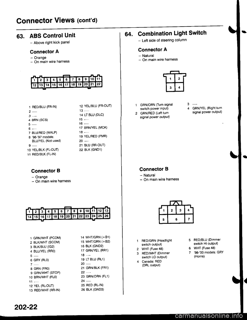
64. Combination Light Switch
- Lett side of steering column
Connector A
- Natural- On main wire harness
GRN/ORN Ourn signal
switch power input)
GRN/RED (Lett turn
signal power outqut)
3
Connector B
- Natural- On main wire harness
RED/GRN (Headlight
switch outpUt)
WHT (Fuse 48)
REDAvHT (Dimmer
switch LO outpu0
Canadar RED(DRL output)
GRN/YEL (Right turn
signal power output)
FED/BLU (Dimmer
switch Hl output)
WHT (Fuse 48)'98100 models: GRY
{Horns)
6
7
Page 2130 of 2189
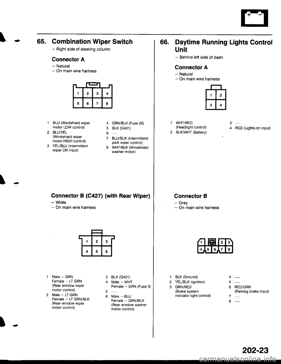
65. Combination Wiper Switch
- Right side ot steering column
Connector A
- Natural- On main wire harness
1BLU (Windshield wipermotor LOW conkol)
BLU/YEL(Windshield wipermotor HIGH control)
YEUBLU (lntermittentwiper ON input)
lilale - GRNFemale - LT GRN(Rear window wipermotor conkol)
lrale - LT GRNFema|e _ LT GRN/BLK(Rear window wipermotor control)
4 GnN/BLK (Fuse 26)
5 BLK (G401)
7 BLU/BLK(lntermittenvpark wiper control)
8 WHT/BLK (Windshieldwasher motor)
BLK (G401)
Male - WHTFemale - GRN (Fuse 3)
Male - BLUF€male _ GRN/BLK(Rear window washermotor control)
\
Connector B (C4271 (with Rear Wiper)
- White- On main wire harness
3
5
6
)
I3
68
13
4
66. Daytime Running Lights Control
Unit
- Behind left side ol dash
Connector A
- Natural- On main wire
WHT/RED(H€adlight control)
BLKAVHT (Battery)RED (Lights-on input)
Connector B
- Gray- On main wire harness
narness
ffi
31
2
1
2
3
BLK (Ground)
YEUBLK (lgnition)
GRN/RED(Brake systemindicator light conkol)
RED/GRN(Parking brake input)
4
5
6
7
8
202-23
Page 2161 of 2189
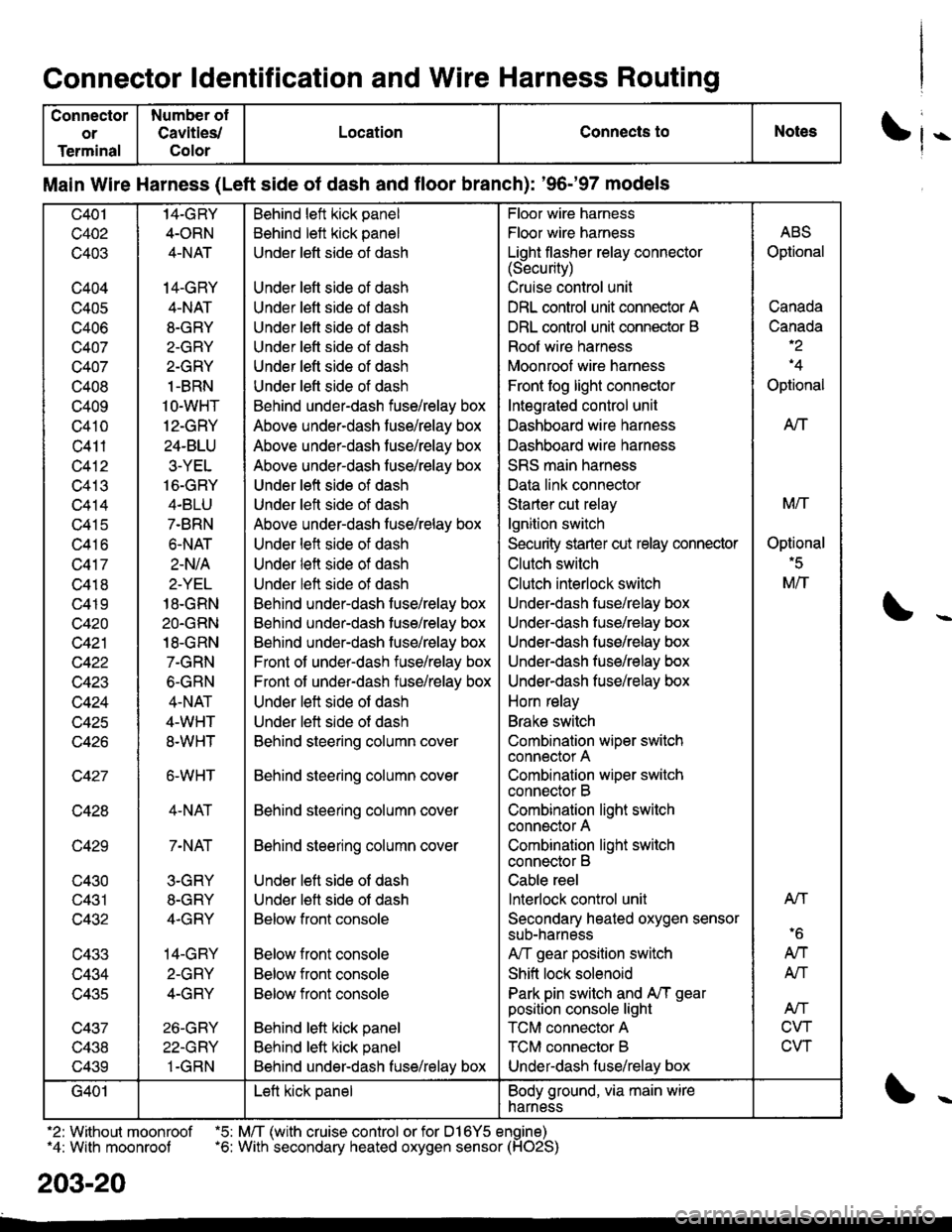
Connector ldentification and Wire Harness Routing
Connector
or
Terminal
Number ol
Cavities/
Color
LocationConnects toNotes
Main Wire Harness (Left side of dash and floor branch): '96-'97 models
c401
c402
c403
c404
c405
c406
c407
c407
c408
c409
c410
c411
c412
c413
c414
c415
c416
c417
c418
c419
c420
c421
c422
w+4J
c424
c425
c427
c428
c429
c430
c431
c432
c433
c434
lJ+OC
c437
v+.to
c439
14-GRY
4-ORN
4-NAT
14-GRY
4-NAT
8-GRY
2-GRY
2-GRY
1-BRN
1O-WHT
12-GRY
24-BLU
3-YEL
16-GRY
4.BLU
7-BRN
6.NAT
2-N/A
2-YEL
18-GRN
2O.GRN
18-GRN
7-GRN
6-GRN
4-NAT
4-WHT
8.WHT
6-WHT
4-NAT
7-NAT
3-GRY
8-GRY
4.GRY
14-GRY
2-GRY
4-GRY
26-GRY
22-GRY
1-GRN
Behind left kick panel
Behind left kick panel
Under left side ot dash
Under left side of dash
Under left side of dash
Under left side of dash
Under lett side ot dash
Under left side of dash
Under left side of dash
Behind under-dash fuse/relay box
Above under-dash fuse/relay box
Above under-dash fuse/relay box
Above under-dash fuse/relay box
Under left side of dash
Under left side of dash
Above under-dash fuse/relay box
Under left side of dash
Under left side of dash
Under left side of dash
Behind under-dash fuse/relay box
Behind under-dash fuse/relay box
Behind under-dash fuse/relay box
Front of under-dash iuse/relay box
Front of under-dash fuse/relay box
Under left side of dash
Under left side of dash
Behind steering column cover
Behind steering column cover
Behind steering column cover
Behind steering column cover
Under left side of dash
Under lett side ot dash
Below front console
Below front console
Below front console
Below front console
Behind lett kick panel
Behind left kick panel
Behind under-dash fuse/relay box
Floor wire harness
Floor wire harness
Light flasher relay connector(Security)
Cruise control unit
DRL control unit connector A
DRL control unit connector B
Roof wire harness
Moonroof wire harness
Front fog light connector
Integrated control unit
Dashboard wire harness
Dashboard wire harness
SRS main harness
Data link connector
Starter cut relay
lgnition switch
Security starter cut relay conneclor
Clutch switch
Clutch interlock switch
Under-dash fuse/relay box
Underdash fuse/relay box
Under-dash fuse/relay box
Under-dash fuse/relay box
Underdash fuse/relay box
Horn relay
Brake switch
Combination wiper switch
connector A
Combination wiper switch
connector B
Combination light swilch
connector A
Combination light switch
connector B
Cable reel
lnterlock control unit
Secondary heated oxygen sensor
sub-narness
A,/T gear position switch
Shift lock solenoid
Park pin switch and A,/T gear
position console light
TCM connector A
TCM connector B
Under-dash luse/relay box
ABS
Optional
Canada
Canada-2
'4
Optional
AtT
M/T
Optional'5
M/T
Atl
'6
AN
AN
Atf
CVT
CVT
G401Left kick panelBody ground, via main wire
harness
.2: Without moonroof .5: M/T (with cruise control or for D16Y5 engine)"4: With moonroof .6: With secondary heated oxygen sensor (HO2S)
203-20
Page 2163 of 2189
Connector ldentification and Wire Harness Routing
Connector
or
Terminal
Number of
Cavities/
Color
LocationConnects toNotess
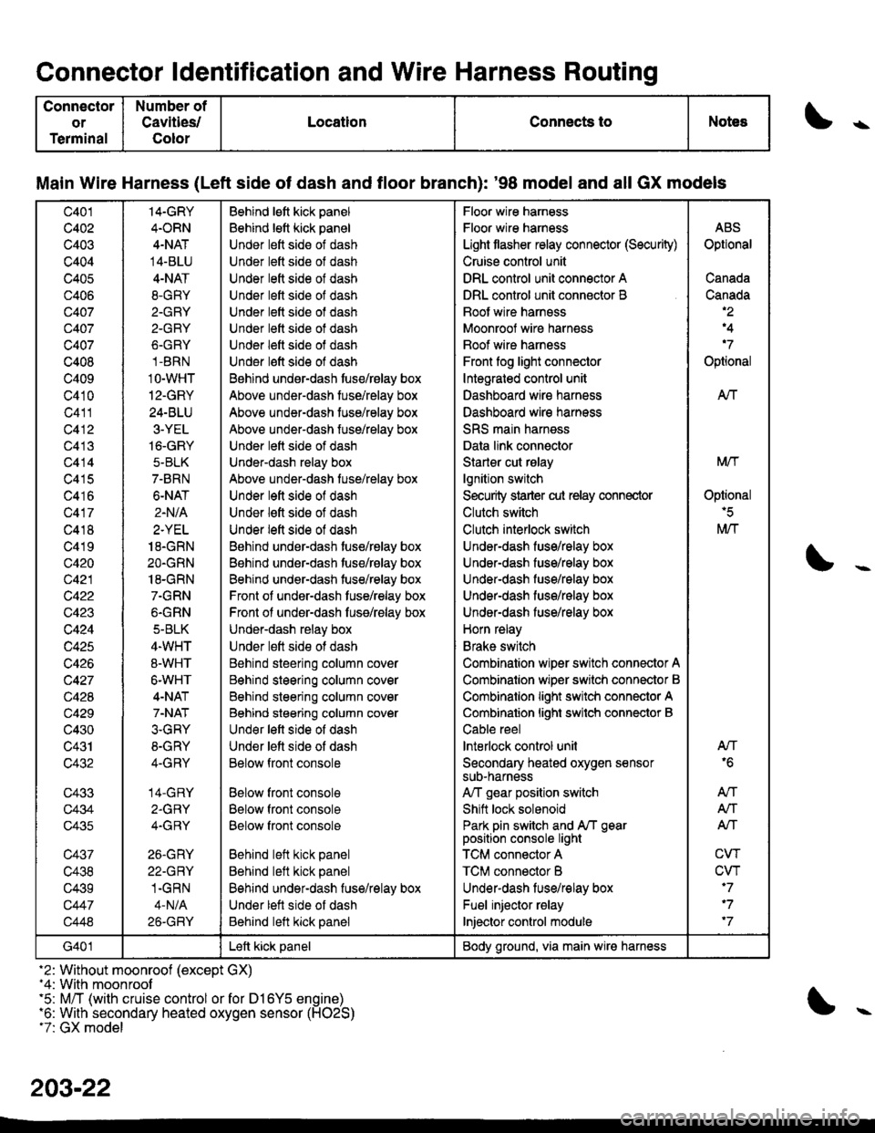
Main Wire Harness (Left side of dash and tloor branch): '98 model and all GX models
c401
c402
c403
c404
c405
c406
Q407
c407
c407
c408
c409
c410
c411
c412
c413
c414
c415
c416
c417
c418
c419
c420
c421
c422
c423
c424
c425
c426
c427
c428
c429
c430
c431
c432
c433
c434
c435
c437
c438
c439
c447
c448
14-GRY
4.ORN
4-NAT
14-BLU
4-NAT
8.GRY
2.GRY
2-GRY
6.GRY
1-BRN
1O-WHT
12-GRY
24-BLU
3-YEL
16-GRY
5-BLK
7-BRN
6-NAT
2.N/A
2.YEL
18.GRN
2O.GRN
18-GRN
7.GRN
6.GRN
5-BLK
4.WHT
8-WHT
6-WHT
4-NAT
7-NAT
3.GRY
8-GRY
4-GRY
14-GRY
2.GRY
4.GRY
26.GRY
22-GRY
1.GRN
4-N/A
26-GRY
Behind lett kick panel
Behind lett kick panel
Under lett side of dash
Under lett side ol dash
Under lett side of dash
Under left side of dash
Under lett side of dash
Under lett side ot dash
Under left side of dash
Under l€ft side of dash
Behind undsr-dash tuse/rBlay box
Above under-dash tuse/relay box
Above under-dash tuse/relay box
Above under-dash fuse/relay box
Under lett side of dash
Under-dash relay box
Above under-dash tuse/relay box
Under left side of dash
Under lett side of dash
Under left side of dash
Behind under-dash tuse/relay box
Behind under-dash tuse/relay box
Behind under-dash tuse/relay box
Front of under-dash tuse/relay box
Front ol under-dash fuss/relay box
Under-dash relay box
Under lett side ot dash
Behind steering column cover
Behind steering column cover
Behind steering column cover
Behind steering column cover
Und€r left side of dash
Under lett side of dash
Below front console
Below front console
Below front console
Below front console
Behind left kick panel
Behind left kick panel
Behind under-dash fuse/relay box
Under lett side of dash
Behind left kick panel
Floor wire harness
Floor wire harness
Light tlasher relay connector (Security)
Cruise control unit
DRL control unit connector A
DRL control unit connector B
Boot wire harnsss
Moonroof wire harness
Boof wire harness
Front fog light connector
Integrated control unit
Dashboard wire harness
Dashboard wire harness
SRS main harness
Data link connector
Starler cut rslay
lgnition switch
Security strarter cut relay connector
Clutch switch
Clutch interlock switch
Under-dash fuse/relay box
Under-dash fuse/relay box
Under-dash fuso/rolay box
UndeFdash fuse/relay box
Under-dash fuse/relay box
Horn relay
Brake switch
Combination wiper switch connector A
Combinalion wiper srvitch connector B
Combinalion light switch connector A
Combinalion lighi swilch connector B
Cable reel
lnterlock control unil
Secondary heated oxygen sensorsuD-narness
A,/T gear position switch
Shift lock solenoid
Park pin switch and A/T gearposition console light
TCM connector A
TCM connector B
Underdash lus€/relay box
Fuel injector relay
Injector control module
ABS
Optional
Canada
Canada,2
,4
'7
Optional
AIf
Mtf
Oplional'5
M/T
AN'6
An
A,/T
Alf
CW
CVT'7
'7
'7
G401Left kick panelBody ground, via main wire harness
-2: Without moonroof (except GX)-4: With moonroof'5: M/T (with cruise control or for D16Y5 engine)'6: With secondary heated oxygen sensor (H02S)t7: GX model
203-22
Page 2165 of 2189
Connector ldentification and Wire Harness Routing
Connector
ol
Terminal
Number ot
Cavlties/
Color
LocationConnects toNotes\
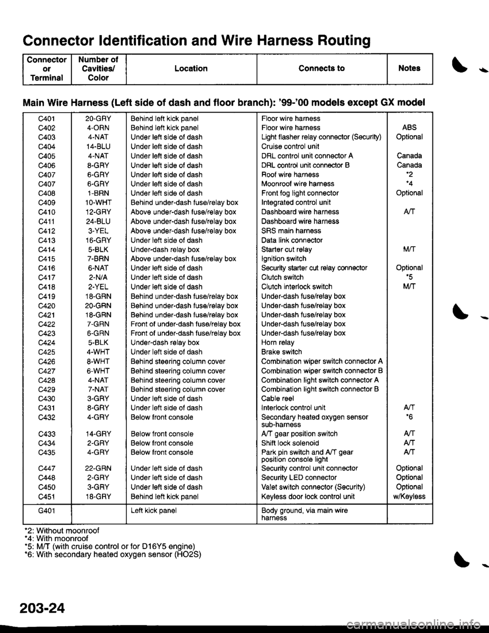
Main Wire Harness (Left side of dash and floor branch): '9$00 models except GX model
c401
c402
c403
c404
c405
c406
c407
c407
c408
c409
c4t0
Q411
c412
c413
c414
c415
c416
c417
c418
c419
c420
c42'l
c423
c424
c425
c426
c42A
c429
c430
c431
c432
c433
c434
c435
c447
c448
c450
c451
2O.GRY
4.ORN
4.NAT
14.BLU
4-NAT
8-GRY
6.GRY
6.GRY
1-BRN
1o-wHT
12-GRY
24-BLU
3.YEL
16-GRY
5.BLK
7-BRN
6.NAT
2-N/A
2-YEL
18.GRN
2O.GRN
18.GRN
7.GRN
6.GRN
5-BLK
4.WHT
8.WHT
6-WHT
4-NAT
7.NAT
3.GRY
8.GRY
4-GRY
14-GRY
2-GFY
4-GRY
22.GRN
2-GRY
3-GRY
18-GRY
Behind left kick panel
Behind left kick panel
Under left side of dash
Under lett side oI dash
Under lett side of dash
Under letl side ol dash
Under lett side oI dash
Under letl side oI dash
Under lefl sids ol dash
Behind under-dash fuse/relay box
Above under-dash fuse/relay box
Above under-dash fuse/relay box
Above under-dash fuse/relay box
Under lett side ot dash
Under-dash relay box
Above under-dash fuse/relay box
Under left side of dash
Under left side ot dash
Under lett side of dash
Behind under-dash fuse/relay box
Behind under-dash fuss/relay box
Behind under-dash fuse/relay box
Front of under-dash fuse/relay box
Front of under-dash fuse/relay box
Under-dash relay box
Under loft side ot dash
Bohind steering column cov6r
B6hind stesring column cover
Behind steering column cover
Behind steering column cover
Under lett side ot dash
Under lett side ot dash
Below fronl console
Below front console
Below front console
Below front console
Under lett side ot dash
Under lett side of dash
Under left side of dash
Behind lett kick panel
Floor wire harness
Floor wire harness
Light flasher relay connector (Sscurity)
Cruise control unil
DRL control unit connector A
DRL control unit conn€ctor B
Roof wire harness
Moonroof wire harnsss
Front tog light connector
Intsgratgd control unit
Dashboard wire harn€ss
Dashboard wire harness
SRS main harness
Data link connector
Starter cut relay
lgnition switch
S€curity starter cut relay connector
Clutch switch
Clulch interlock switch
Under-dash fuse/relay box
Under-dash tuse/ralay box
Under-dash tuse/ralay box
Under-dash fuse/relay box
Under-dash fuse/relay box
Horn relay
Brake switch
Combination wiper switch connector A
Combination wiper switch conn€ctor B
Combination light switch connector A
Combination light switch conn€ctor B
Cable reel
lnterlock control unit
Secondary heated oxygen sensorsub-narnsss
A/T gsar position switch
Shitt lock solenoid
Park pin switch and A/T gearposition consolo light
Security control unit connactor
Security LED connector
Valet switch connector (Security)
Keyless door lock control unit
ABS
Optional
Canada
Canada
Optional
AN
Mrl
Optional'5
M/T
AN'6
An
Atf
Atf
Optional
Optional
Optional
MKoyloss
G401Left kick panelBody ground, via main wirenarness
'2: Without moonroof"4: With moonroof'5: M/T (with cruise control or for D16Y5 engine)'6: With secondary heated oxygen sensor (HO2S)
203-24