HONDA CIVIC 1998 6.G Workshop Manual
CIVIC 1998 6.G
HONDA
HONDA
https://www.carmanualsonline.info/img/13/6068/w960_6068-0.png
HONDA CIVIC 1998 6.G Workshop Manual
Trending: ground clearance, Cat transmission, Floor Harness, Pads, transmission label, air suspension, Air condition
Page 341 of 2189
System Description
System Connectors [Engine Compartment] (cont'dl
816A2 engins:
11-72
Page 342 of 2189
c105
ffi
C10,1(Canadal
I rlz 3l
16lwHrsEo. -l
I2 BLK/YEL IftlwHri BLUIl'l
cl t3
D
c123
ffil3 4l
c104
l1 2l
l-f.l
c102
F1+..rl1 2 3l
ffl'wHnr€D" --.l
ItrERlxBLa__llo."llBurntotl-l
c101
C11il
ffi
c137
a
c108
ffi
c107
ffi
c106
ffi
c302
tu
c138
A
v
FTBtKiBLtr__llZTYEuBLKi l
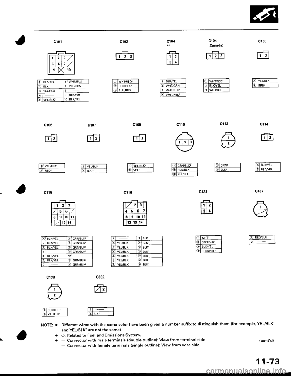
NOTE: oDifferent wires with the same color have been given a number suffix to distinguish them (for example, YEUBLKl
and YEUBLK'�are not the same).
O: Related to Fuel and Emissions Svstem.a
(cont'd)
11-73
- Connector with male terminals (double outline): View from terminal side
- Connector with female terminals (single outline): View from wire side
.1'BLKYEL6WHT/BLU
eBLKI1YEUGRN
3YEUREO89BLKryVFT5lYEUBLKI10BLK,ryEL
BLK^/EL:d)GBN/BLK'2BLK/YELGRN/8LK'3BLK,YELGRN/BLK'rljGRN/BLK'ELKTYEL12BLI(YELrtGFN/BLK'!l
Page 343 of 2189
System Description
System Connectors [Engine Gompartmentl (cont'd]
81642 enginoi
v
11-74
Page 344 of 2189
c122
A,g
l-iln'eo*r,vHr__-ll[lcRNiBLitl]l
cl17
r'trTl
16lBLK,-__-llO BLX,\,E[ |
16l Btu/wil-
c112
ffi
Cliro
o
C1'11
ffi
l6l-ciN/YEL' _-l
NOTE: . Different wires with the same color have been given a number suffix to distinguish them (for example, YEUBLK1
and YEUBLK'�are not the same).
O: Related to Fuel and Emissions System,- Connector with male terminals (double outline): View from terminal side
- Connector with female terminals (single outline): View from wire side
c'54*1
frl zlsl
fflErKwH---llOlBLr I
f6lGrrunEp -l
11-75
Page 345 of 2189
System Description
a
a
a
System Connectors [Dash and Floor]
('99 - fil models except D16Y5 engine with M/Tl
L
11-76
L
Page 346 of 2189
v1s8l7l6le t0r l!21
' S€cuitAr.h Sysi.m
cL5lwithod cruir. cort?oll
c510 ta/T)
;--F--trt2l
w
l-T - --l
l. - I
elz5{with crui* codrol)
r'ffitr
13 rl
lElwHT"cRN I
YELf,ED/BLK.!
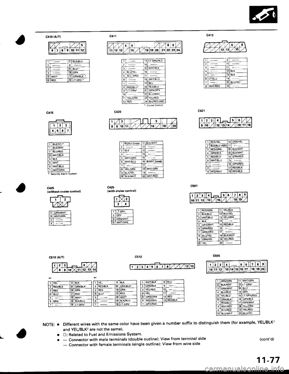
- Connector with male terminals (double outline): View from terminal side
- Connector with female terminals (single outline): View from wire side
Different wires with the same cotor have been given a number suffix to distinguish them (for example, YEUBLKl
and YEUBLK'�are not the same).
O; Related to Fuel and Emissions System
Dt!
t-
NOTE: o
a
a(cont'd)
11-77
t213t5
5
14i!aL(LTATU
1
Et0t1,/ ./ie /1Al,/ 20
2a
9t0l213111 /l61718
!t
t1t
23I7a9
101112t3/lr5l/18 t9
12
YEL
YEL3LK2
Page 347 of 2189
System Description
System Connectors lDash and Floor] (cont'dl
('99 - 00 mod€ls oxc€pt Dl6Y5 ongine with M/T)
11-78
Page 348 of 2189
c130
I10
l112131,4t5ta11t8t9
ct3r
1lz3lt/X61789to
cr34 tEcM/PCM-C)cr35 lPCM-Dr:cr35lPcl|.D,€
ca32
lr 2 3.1
IiGTNiBN Ill
l5l-wxr,nol]ll:a BLX vHI I
NOTE; . Different wires with the same color have been given a number suffix to distinguish them (for example, YEUBLK1
and YEUBLK, are not the samel.
O: Related to Fuel and Emissions Svstem.- Connector with male terminals (double outline): View from terminal side
- Connector with female terminals (single outline): View from wire side
lrl2l
lll* -_-l
tn Bs I
c1a
lr 2l
f.fil
,bl onrrwlrl.lftlBLrwHri-Flirx,lvHJ l]-l
c,|52 tEcM/PCM-Al
\-a
't/3l-1.51
/tgto 'lt12l3
2at6IE e t|0111'12ItItIt[l
11-79
Page 349 of 2189
System Descriptions
System Connectors lFuel Pump]
('9!, - 00 models 6xcept Dl6Y5 ongino with M/T)
\(
I
c568
ffi
c565
E
c792
Different wires with the same color have been given a number suffix to distinguish them (for example, YEUBLKIand YEVBLK, are not the same).
O: Related to Fuel and Emissions System.- Connector with male terminals (double outline): View from terminal side- Connector with female terminals (single outline): View from wire side
c793
fr
NOTE: o
a
a
1 1-80
Page 350 of 2189

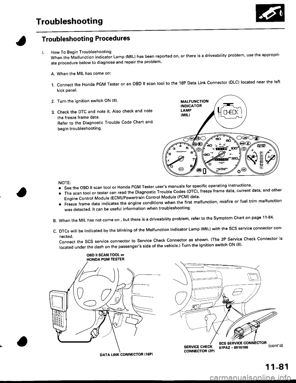
Troubleshooting
Troubleshooting Procedures
How To Begin Troubleshooting
When the Malfunction Indicator Lamp (MlL) has been reported on, or there is a driveability problem, use the appropr'-
ate orocedure below to diagnose and repair the problem'
A. When the MIL has come on:
,1. connect the Honda PGM Tester or an oBD ll scan tool to the 16P Data Link connector (DLC) located near the left
kick panel.
2. Turn the ignition switch ON (ll)
3. Check the DTC and note it. Also check and note
the freeze trame data
Refer to the Diagnostic Trouble Code Chart and
begin troubleshooting.
NOTE:
.SeetheoBD||scantoolorHondaPGMTesteruser,smanua|sforspecificoperatinginstructions..
.Thescantoo|oltestercanreadtheDiagnosticTroub|ecodes(DTc},freezeframedata,currentdata,andother
Engine Control Module (ECM)/Powertrain Control Module (PCM) data'
oFreezeframedataindicatestheengineconditionswhenthefirstma|function,misfireorfue|trimma|function
was detected. lt can be useful information when troubleshooting'
B. When the MIL has not come on , out there is a d riveability problem, refer to the Symptom Chart on page 1 1-84'
c.DTcswi|lbeindicatedbytheb|inkingoftheMa|function|ndicatorLamp(M|L)withthescsserviceconnectorcon.
nected.
Connect the SCS service connector to Service Check Connector as shown (The 2P Service Check Connector is
|ocatedunderthedashonthepassenger,ssideofthevehic|e')TurntheignitionswitchoN{||)'
OBO ll SCAN TOOL olHONOA PGM TESTER
SERVICE CHECKCONNECTOR I2P)
scs sERvlcE(cont'd)
MALFUNCTIONINDICATORLAMP
DATA LINK CONNECTOR Il6PI
07PAZ - (x)l0100
11-81
Trending: ECT sender, B16 top end, Connector c110, Model, Knock sensor, Rear driver side, fuse diagram
![HONDA CIVIC 1998 6.G Workshop Manual System Description
System Connectors [Engine Compartment] (contdl
816A2 engins:
11-72 HONDA CIVIC 1998 6.G Workshop Manual System Description
System Connectors [Engine Compartment] (contdl
816A2 engins:
11-72](/img/13/6068/w960_6068-340.png)

![HONDA CIVIC 1998 6.G Workshop Manual System Description
System Connectors [Engine Gompartmentl (contd]
81642 enginoi
v
11-74 HONDA CIVIC 1998 6.G Workshop Manual System Description
System Connectors [Engine Gompartmentl (contd]
81642 enginoi
v
11-74](/img/13/6068/w960_6068-342.png)
![HONDA CIVIC 1998 6.G Workshop Manual c122
A,g
l-ilneo*r,vHr__-ll[lcRNiBLitl]l
cl17
rtrTl
16lBLK,-__-llO BLX,\,E[ |
16l Btu/wil-
c112
ffi
Cliro
o
C111
ffi
l6l-ciN/YEL _-l
NOTE: . Different wires with the same color have been given a n HONDA CIVIC 1998 6.G Workshop Manual c122
A,g
l-ilneo*r,vHr__-ll[lcRNiBLitl]l
cl17
rtrTl
16lBLK,-__-llO BLX,\,E[ |
16l Btu/wil-
c112
ffi
Cliro
o
C111
ffi
l6l-ciN/YEL _-l
NOTE: . Different wires with the same color have been given a n](/img/13/6068/w960_6068-343.png)
![HONDA CIVIC 1998 6.G Workshop Manual System Description
a
a
a
System Connectors [Dash and Floor]
(99 - fil models except D16Y5 engine with M/Tl
L
11-76
L HONDA CIVIC 1998 6.G Workshop Manual System Description
a
a
a
System Connectors [Dash and Floor]
(99 - fil models except D16Y5 engine with M/Tl
L
11-76
L](/img/13/6068/w960_6068-344.png)

![HONDA CIVIC 1998 6.G Workshop Manual System Description
System Connectors lDash and Floor] (contdl
(99 - 00 mod€ls oxc€pt Dl6Y5 ongine with M/T)
11-78 HONDA CIVIC 1998 6.G Workshop Manual System Description
System Connectors lDash and Floor] (contdl
(99 - 00 mod€ls oxc€pt Dl6Y5 ongine with M/T)
11-78](/img/13/6068/w960_6068-346.png)
![HONDA CIVIC 1998 6.G Workshop Manual c130
I10
l112131,4t5ta11t8t9
ct3r
1lz3lt/X61789to
cr34 tEcM/PCM-C)cr35 lPCM-Dr:cr35lPcl|.D,€
ca32
lr 2 3.1
IiGTNiBN Ill
l5l-wxr,nol]ll:a BLX vHI I
NOTE; . Different wires with the same color have be HONDA CIVIC 1998 6.G Workshop Manual c130
I10
l112131,4t5ta11t8t9
ct3r
1lz3lt/X61789to
cr34 tEcM/PCM-C)cr35 lPCM-Dr:cr35lPcl|.D,€
ca32
lr 2 3.1
IiGTNiBN Ill
l5l-wxr,nol]ll:a BLX vHI I
NOTE; . Different wires with the same color have be](/img/13/6068/w960_6068-347.png)
![HONDA CIVIC 1998 6.G Workshop Manual System Descriptions
System Connectors lFuel Pump]
(9!, - 00 models 6xcept Dl6Y5 ongino with M/T)
\(
I
c568
ffi
c565
E
c792
Different wires with the same color have been given a number suffix to disti HONDA CIVIC 1998 6.G Workshop Manual System Descriptions
System Connectors lFuel Pump]
(9!, - 00 models 6xcept Dl6Y5 ongino with M/T)
\(
I
c568
ffi
c565
E
c792
Different wires with the same color have been given a number suffix to disti](/img/13/6068/w960_6068-348.png)
