relay HONDA CIVIC 1998 6.G Workshop Manual
[x] Cancel search | Manufacturer: HONDA, Model Year: 1998, Model line: CIVIC, Model: HONDA CIVIC 1998 6.GPages: 2189, PDF Size: 69.39 MB
Page 2053 of 2189
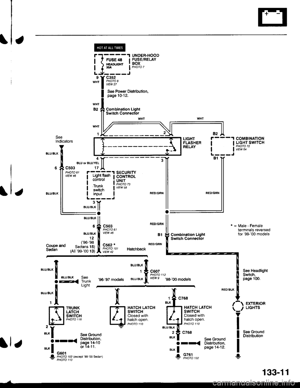
UNDER.HOODl t FUsE4s I FUSEiRELAY! xamucnr ! BoX
I I.A I PHoro 7
LJ,----Jc352
vtEw 27
Soe Pow€r Distdbulion,page 1&12,
Combination LightSwitch ConnectorE2
SeelndicatorsCOMBINATIONI I LIGHT SWITCH
| | v;iw; -
LIGHTFLASHERRELAY
4aLU or ALU/YEI
c503
iTFffiliBi+B,il:"'s#Ji"" I coNrRoL
i#$ iI input IL ----J3YBLU/BLK ll:aBrui 8rK ll
*,rlfr ftT-f.","
,^ftslllfl li^ir,, Ha,chback
vtEw 58
Coupa tndSedan
Combination LightSwitqh Connector
r = l\,lale - Femaletermrnals reversedlor'99-'00 models
See HeadlightSwiich,peg61(n.
EXTERIORLIGHTS
Seo GroundDistribution
"'u'"t*X
".u,"."aE,<
-*;"1
SeeTrunkLight
'9+ 97 models
aau,"a" fi
'*9#1",,,
BLU/BLKrf vEwe g8-,oo modets
l
qi*$qli-
TRUNKLATCHswrTcH
":^f se€ Ground
5--r< !#itl8".* I o"o'
or 14-11
.|- PHOIO ro2lorcoDr'99 oo sedan): PHofo 113
";-f "^'
FE
I-I-t HATCH LATCHI I I swtrcx
lljij::,:}#x""'*if
"tut
seecroundo tr
e.* | Page 14-12'
+ 9131",,,
133-11
Page 2054 of 2189
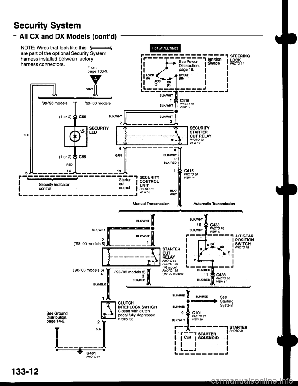
Security System
- All CX and DX Models (cont'd)
NOTE: Wires that look like this S--------S
are part ol the optional Security System
harness installed between lactory
harness connectors.Frompage j33_9.
@
aLI(AVHI
IAIKWHT
STEERINGLOCK
v
""'ll
'99198 models
(l or
1T
Jl.
'99100 models
sEcuRrwLEO
c415
vlEw 14
l-
SECURITYSTARTERCUT RELAYPHO|O 53vtEw 12
BLI(FEO't1
au(/FEo
c433
Aubrnatb Transmission
c4r 5PHOTO N
AU(WHT't0
BLXAVI{TBLKT'!VHT
2('98-'00 mod€ls 5)
('98100 models 3)4
A"IT GEARPOStTTONswtTcH
".**"rI
[ :,iSTARTERCUTRELAYPHO|O 54PHO|O 129( 9€ model)
( 9+ 00 models)
?
I
I
I
I
I
1-sel-oo rnJ"ls z1'[
".*"9tr
c433
CLUTCHINTERLOCK SWITCHClosed with clutchpedaltully depressed.
".o""0! ".o".0 seeaE4 Starting
ar-rvneo ll System
'f, "";%,,BLK TTBT I
vrEw28
r-11------.|STABTER
! r3r smnren I PHoro 34
| 1 coit ; SoLENOID I
i !.__J iL--------J
"===-F=F*F,Ff
Tfo?"
It -,/ Pase 10 l
!ltb3'-fi:-#-1iln i
ll .",;T; "":JI------;;lt
ll *"ll ll ELKBEDII
,JL----- 'dl*------ 'll t{
paso 14€. " y
I
*-l
L_______l.------+;_ -
PHO|OST
133-12
Page 2057 of 2189
Ir
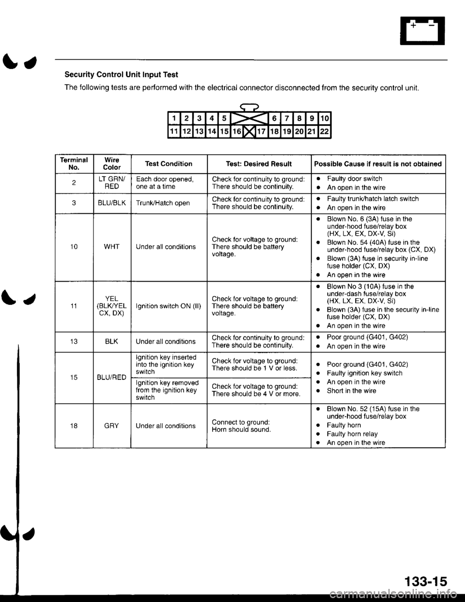
Security Control Unit Input Test
The following tests are performed with the electrical conneclor disconnected from the security control unit.
\;
12345X67I910
1112131415rol171819202122
TerminalNo.WireColorTest ConditionTest: Desired ResultPossible Cause il result is not obtained
2LT GRN/REDEach door opened,one at a timeCheck for conlinuity to ground:
There should be continuity.
Faulty door switch
An open in the wirea
3BLU/BLKTrunUHatch openCheck for continuity to ground:
There should be continuity.
aFaulty trunldhatch latch switch
An open in the wirea
10WHTUnder all conditionsCheck tor voltage to ground:
There should be batteryvoltage.
. Blown No. 6 (3A) fuse in theunder-hood fuse/relay box(HX, LX, EX, DX-V Si)
. Blown No. 54 (40A) fuse in theunder-hood fuse/relay box (CX, DX)
. Blown (3A) fuse in security in-linefuse holder (CX, DX)
. An open in the wire
11YEL(BLK/YEL
cx, DX)lgnition switch ON (ll)Check for voltage to ground:
There should be batteryvoltage.
. Blown No 3 (10A) fuse in theunder-dash tuse/relay box(HX, LX, EX, DX.V, Si)
. Blown (3A) fuse in the security in-linefuse holder (CX, DX)
. An open in the wire
BLKUnder all conditionsCheck for continuity to ground:
There should be continuity.
aPoor ground (G401, G402)
An open in the wirea
t5BLU/RED
lgnition key insertedinto the ignition keyswitch
Check for voltage to ground:
There should be 1 V or less.aPoor ground (G401, G402)
Faulty ignition key switch
An open in the wire
Short in the wire
a
a
algnition key removedfrom the ignition keyswitch
Check for voltage to ground:
There should be 4 V or more.
18GRYUnder all conditionsConnect to ground:
Horn should sound.
. Blown No.52 (15A) luse in theunder-hood luse/relay box
. Faulty horn
. Faulty horn relay
. An open in the wire
133-15
Page 2058 of 2189
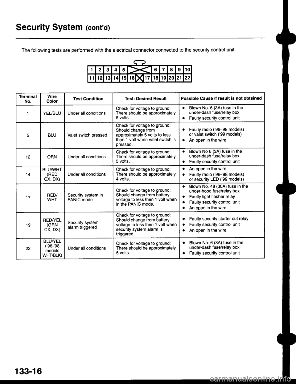
Security System (cont'd)
The following tests are performed with the electrical connector connected to the security control unit.
133-16
TerminalNo.WireColorTest ConditionTest: Desired ResultPossible Cause il result is not obtained
1YEUBLUUnder all conditionsCheck tor voltage to ground:
There should be approximately
5 volts.
aBlown No. 6 (3A) fuse in theunder-dash fuse/relay box
Faulty security control unita
5BLUValet switch pressed
Check tor voltage to ground:
Should change from
approximately 5 volts to less
than 1 volt when valet switch isprsssed.
aFaulty radio ('96-98 models)
or valet switch ('99 models)
An open in the wirea
12ORNUnder all conditionsCheck for voltage to ground:
There should be approximately5 volts.
aBlown No 6 (3A) tuse in tho
under-dash tuse/relay box
Faulty security control unito
14
BLU/WHT(BED
CX, DX)Under all conditions
Check for voltage to ground:
There should be approximately4 volts.
. An open in the wire
. Faulty radio ('96198 models)
or security LED ('99 models)
17RED/WHTSecurity system inPANIC mode
Check for voltage to ground:
Should change from batteryvoltage to less then 1 volt whenin the PANIC mode.
aBlown No. 48 (30A) luse in the
under-hood fuse/relay box
Faulty light flasher relay
Faulty security conlrol unit
An open in the wire
a
a
a
19
REDI/EL(GRN
cx, DX)
Security systemalarm triggered
Check tor voltags to ground:
Should change from batteryvoltage to less then 1 volt whensecurity system alarm istriggsred.
aFaulty security starler cut relay
Faulty security control unit
An open in the wire
I
a
22
BLUA/EL/'oa-'oq
mooelsWHT/BLK)
Under all conditionsCheck tor voltage to ground:
There should be approximately
5 volts.
aBlown No. 6 (3A) fuse in the
under-dash fuse/relay box
Faulty security control unita
Page 2066 of 2189
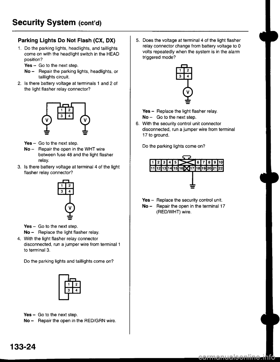
Security System (conrd)
Parking Lights Do Not Flash (CX, DX)
1 . Do the parking lights, headlights, and taillights
come on with the headlight switch in the HEAD
position?
Yes - Go to the next step.
No - Repair the parking lights, headlights, or
taillights circuit.
2. ls there battery voltage at terminals 1 and 2 of
the light flasher relay connector?
dHl
.t.
Yes - Go to the next step.
No - Repair the open in the WHT wire
between fuse 48 and the light flasher
relay.
ls there battery voltage at terminal 4 of the light
flasher relay connector?
-F-,
tlllJt3l4l
Intvl
r=
Yes - Go to the next step.
No - Replace the light flasher relay.
With the light flasher relay connector
disconnected, run a jumper wire from terminal 1
to terminal 3.
Do the parking lights and taillights come on?
Yes - Go to the next step.
No - Repair the open in the RED/GRN wire.
133-24
5. Does the voltage at terminal 4 of the light flasher
relay connector change from battery voltage to 0
volts repeatedly when the system is in the alarm
triggered mode?
Yes - Replace the light flasher relay.
No - Go to the next step.
With the security control unit connector
disconnected, run a jumper wire from termrnal
17 to ground.
Do the parking lights come on?
Yes - Replace the security control unit.
No - Repair the open in the terminal 17
(REDAIVHT) wire.
q
I=
Page 2067 of 2189
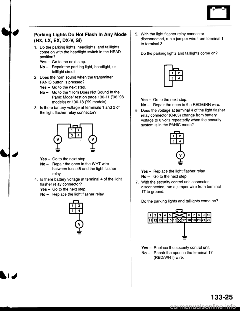
Parking Lights Do Not Flash In Any Mode
(HX, LX, EX, DX-V Si)
1. Do the parking lights, headlights, and taillights
come on with the headlight switch in the HEAD
oosition?
Yes - Go to the next steo.
No - Repair the parking light, headlight, or
taillight circuit.
2. Does the horn sound when the transmitter
PANIC button is oressed?
Yes - Go to the next step.
No - Go to the "Horn Does Not Sound In the
Panic Mode" test on page 130-11 ('96-98
models) or 1 30-18 ('99 models).
3. ls there battery voltage at terminals 1 and 2 of
the light flasher relay connector?
Yes - Go to the next step.
No - Reoair the open in the WHT wire
behveen fuse 48 and the liqht flasher
reray.
ls there battery voltage at terminal 4 ol the light
flasher relay connector?
Yes - Go to the next steD.
No - Replace the light flasher relay.
133-25
5. With the light flasher relay connector
disconnected, run a jumper wire from terminal .l
to terminal 3.
Do the parking lights and taillights come on?
o.
Yes - Go to the next step.
No - Repair the open in the RED/GRN wire.
Does the voltage at terminal 4 of the light flasher
relay connector (C403) change from battery
voltage to 0 volts repeatedly when the security
svstem is in the PANIC mode?
Yes - Replace the light flasher relay.
No - Go to the next steP.
7. With the security control unit connector
disconnected, run a jumper wire from terminal
17 to ground.
Do the parking lights and taillights come on?
Yes - Replace the security conlrol unit.
No - Repair the open in the terminal 17
(REDMHT) wire.
q
I=
Page 2069 of 2189
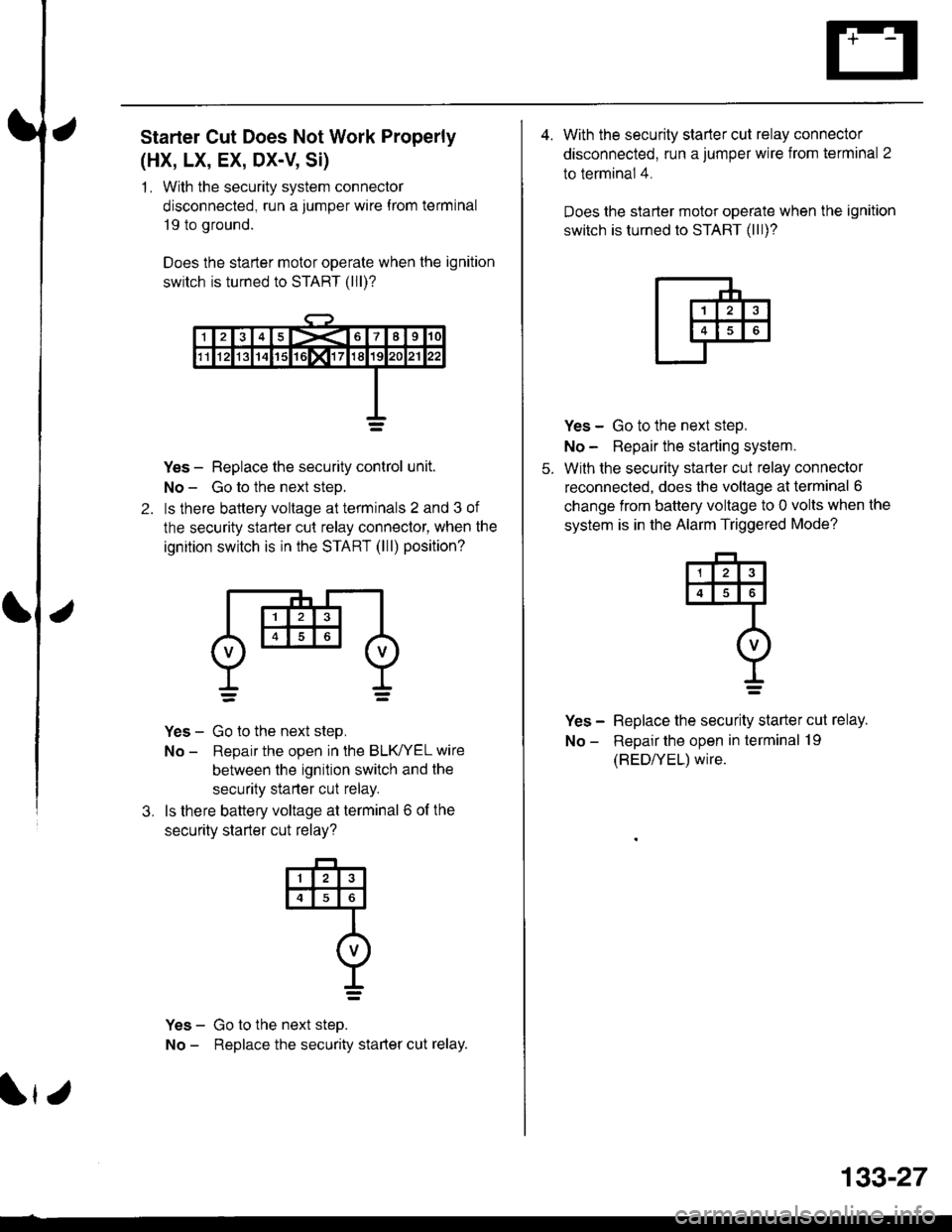
Starter Cut Does Not Work Properly
(HX, LX, EX, DX-V, Si)
1 . With the security system connector
disconnected, run a jumper wire f rom terminal
19 to ground.
Does the starter motor operate when the ignition
switch is turned to START (lll)?
2.
Yes - Replace the security control unit.
No - Go to the next steD.
ls there baltery voltage at terminals 2 and 3 of
the security starter cut relay connector, when the
ignition switch is in the START (lll) position?
Yes - Go to the next step,
No - Reoair the ooen in the BLK/YEL wire
between the ignition switch and the
security starter cut relay.
ls there battery voltage at terminal 6 of the
securitv starter cut relav?
Yes - Go to the next steo.
No - Replace the security starter cut relay.
3.
@
I=
r
133-27
4. With the security starter cut relay connector
disconnected, run a jumper wire from terminal 2
to terminal 4.
Does the slarter motor operate when the ignition
switch is turned to START (lll)?
5.
Yes - Go to the next step,
No - Repair the starting system.
With the security starter cut relay connector
reconnected, does the voltage at terminal 6
change from battery voltage to 0 volts when the
system is in the Alarm Triggered Mode?
Yes - Replace the security starter cut relay.
No - Repair the open in terminal 19
(BED/YEL) wire.
4
I=
Page 2070 of 2189
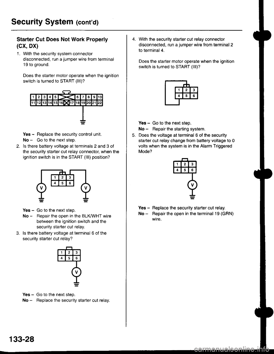
Security System (cont'd)
Starter Cut Does Not Work Properly
(cx, Dx)
1 . With the security system connector
disconnected, run a jumper wire f rom terminal
19 to ground,
Does the starter motor operate when the ignition
switch is turned to START (lll)?
Yes - Replace the security control unit.
No - Go to the next steo.
ls there battery voltage at terminals 2 and 3 of
the security starter cut relay connector, when the
ignition switch is in the START (lll) position?
Yes - Go to the next step.
No - Repair the open in the BLKMHT wire
between the ignition switch and the
security starter cut relay.
ls there battery voltage at terminal 6 of the
securitv starter cut relav?
Yes - Go to the next step.
No - Beplace the security starter cut relay.
4
o
t_=
133-28
4. With the security starter cut relay connector
disconnected, run a jumper wire from terminal 2
to terminal 4.
Does the starter motor operate when the ignition
switch is turned to START (lll)?
Yes - Go to the next steo.
No - Repair lhe starting system.
Does the voltage at terminal 6 of the security
starter cut relay change trom battery voltage to 0
volts when the system is in the Alarm Triggered
Mode?
Yes - Replace the security starter cut relay.
No - Repair the open in the terminal 19 (GRN)
wtre.
q
I=
Page 2074 of 2189
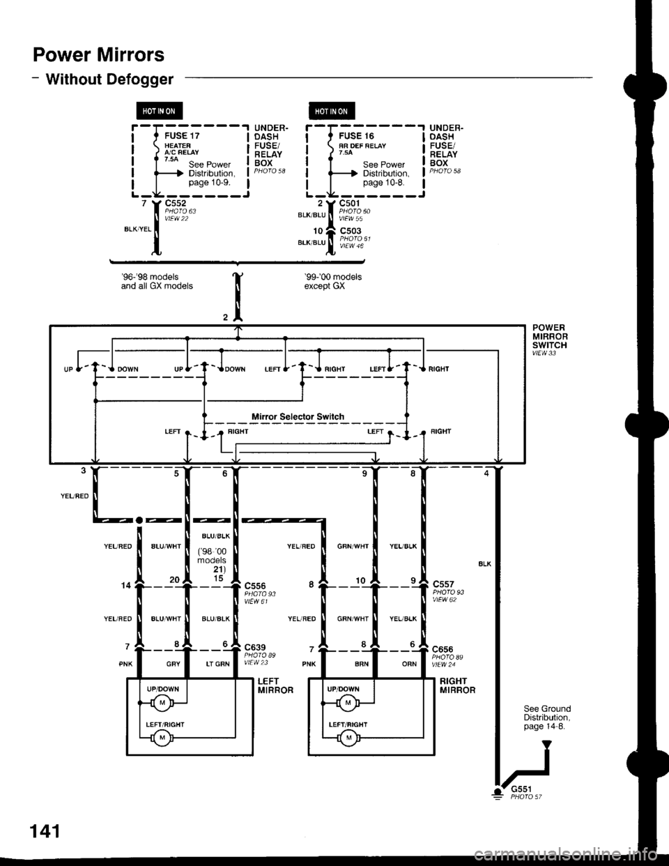
Power Mirrors
- Without Defogger
r,-;;---j HEAIEF 1/ A/C FEIAY
I t uo s"" Po*", !f-----f Distribution, I
L_i:i:_J
UNDER-DASH
RELAYBOX
UNDER-OASHFUSE/RELAYBOX
I
I
I
I
I
BLK/BLU
10
BLK/BLU
-l
I
I
I
I
IJ
f,-G;---
I See Power
lF---t Distribution,
L_i:i'i_
rt;%,"
*'ii%.,
L vtEW 46
vlEw 22
'96-'98 modelsand all GX models
'99r00 modelsexcept GX
a-
c639
vlEW23
c656
POWERMIRBORswtTcHvtEw 33
See GroundDistribution,page 14-8.
LEFTMIRRORRIGHTMIRROR
G-t
BLU/BLK
('98 00mooets2't)15
BLU/ALK
LT GRN
G551
141
Page 2078 of 2189
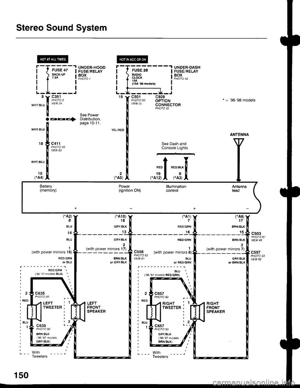
Stereo Sound System
i.l
-"r,"atrf
;;-;l P,)r'=.,8-Jl3g"BA.K.IJP | ?pJ" ,I
I
c351
FUSE 28RAOIOCLOCK
(15A 9A no{br.)
c501
vlEw 55
UNDER-DASHFUSE/RELAYBOX
't9c928OPTIONCONNECTOR
* = '96.�98 models
aa4,See PowerDistribution,page 10-11.
18c411
vlEw 60
See Dash andConsole Lights
.^fi;l ;,tr
rA2)8
BLU
14
BLU
1(with power mirrors 16)
REO/GFNor BLU
I RED/GRN I' (96 s7 moders BLU) r
ra10)18
GRY/BLK
13
(with power mirror6 17)
BRN/BLKor GRYIBIK
rAe)17
BFN/ALK
BRN/BLK
(with power mirrors 7)
RED/GRN
1C556 (with oower milors 6)PHA|O93vtEw 61 aLUor RED/GRN
,ELU,' (s6 97 modes FEO/GFN)
ra1)?
REO/GFN
c503
GFY/BLKor BRN/ALK
c557
vtEw 62
' RED
, BLU,1
.'I LEFTI I TWEETERRIGHT . 1
TWEETER.
c6s7
GFY/BLK
BFN/BLK)
150
Tweeters