relay HONDA CIVIC 1998 6.G Workshop Manual
[x] Cancel search | Manufacturer: HONDA, Model Year: 1998, Model line: CIVIC, Model: HONDA CIVIC 1998 6.GPages: 2189, PDF Size: 69.39 MB
Page 2122 of 2189
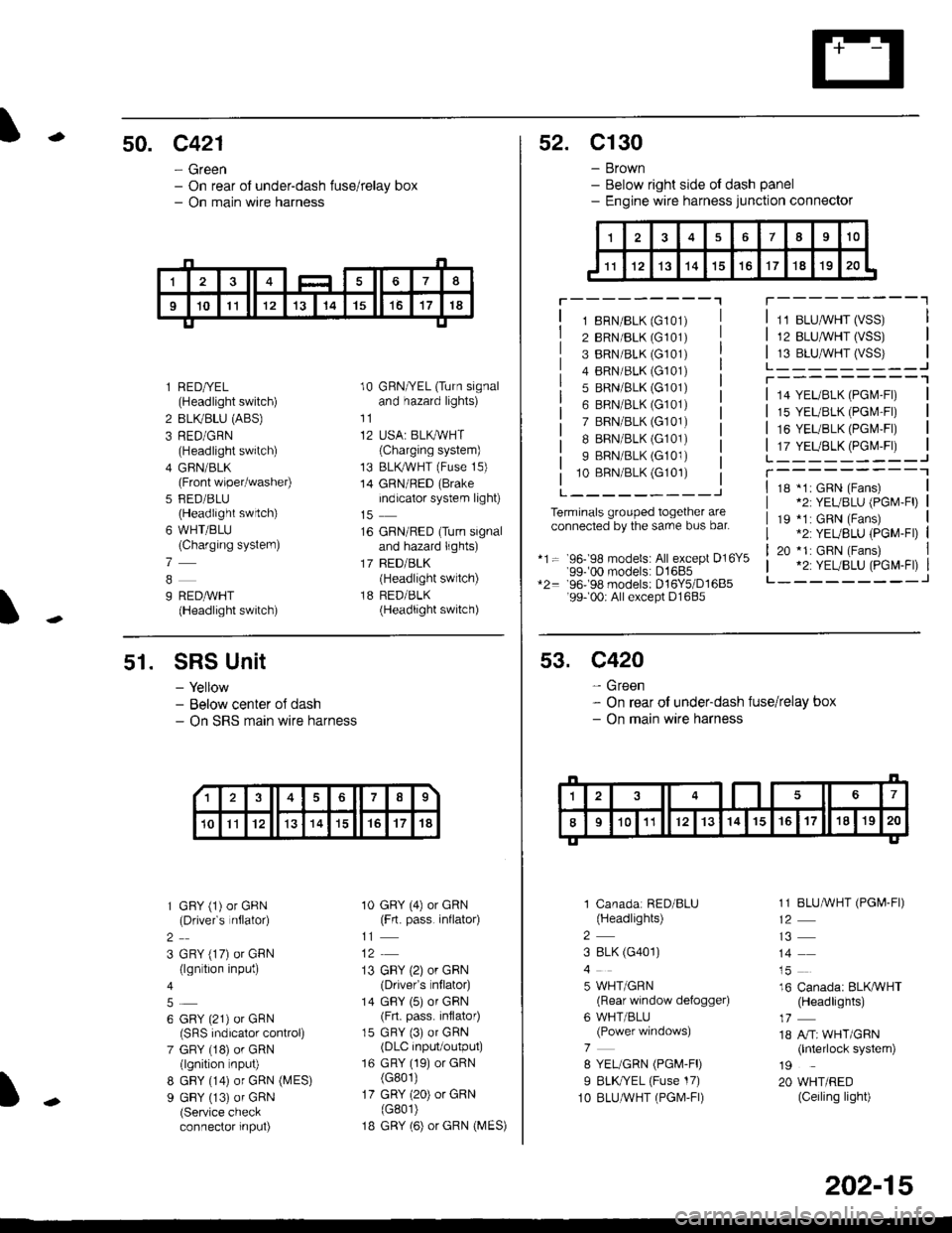
-50. c421
- Green- On rear of under-dash fuse/relay box- On main wire harness
I
l RED/YEL(Headlight switch)
2 BLIVBLU (ABS)
3 RED/GRN(Headlight switch)
4 GFIN/BLK(Front wiper/washer)
5 FED/BLU(Headlight swrtch)
6 WHT/BLU(Charging systern)
7
9 REDAVHT(Headlight switch)
10 GRN/YEL (Turn signaland hazard lights)
11
12 USA: BLKAVHT(Charging system)
13 BLKryVHT (Fuse 15)
14 GRN/RED (Brake
indicator system light)
16 GRN/RED (Turn signaland hazard lights)
17 BED/BLK(Headlight switch)
18 RED/BLK(Headlight switch)
52. C130
- Brown- Below right side ot dash panel- Engine wire harness junction connector
T---------"1
1 8RN/BLK (G101)
2 BRN/BLK (G101)
3 BRN/BLK (G101)
4 BRN/BLK (G101)
5 BRN/BLK (G101)
6 BRN/BLK (G101)
7 BRN/BLK (G101)
I BRN/BLK (G101)
9 BRN/BLK (G101)
10 BBN/BLK (G101)
L---------J
Terminals grouped together areconnected by the sarre bus bar.
*1= 96- 98 models: All except D16Y5'99-'00 models: D1685*2= 96-98 models: D16Y5/D1685'99- 00r All except D1685
11 BLUMHT (VSS)
12 BLU,ryVHT (VSS)
13 BLU,^/VHT (VSS)L_-_____--Jr---------'1
14 YEL/BLK (PGl\4-Fl)
15 YEL/BLK (PGr\4'Fr)
16 YEUBLK (PGI\4,FI)
17 YEUBLK (PGr\4,Fr)L______---JT----------118 *1: GRN (Fans)*2: YEUBLU (PGM-Fl)
19 *1: GRN (Fans).2: YEUBLU (PGM-Fl)
20 *1: GRN (Fans).2: YEUBLU (PGM-Fl)_______--J
51. SRS Unit
- Yellow- Below center oJ dash- On SRS marn wire harness
1 GFY (1) or GRN(Drivefs nflator)
2
3 GRY (17) or GRN(lgn tion input)
6 GRY (21) or GRN(SRS indicalor control)
7 GRY (18) or GRN(lgnition nput)
8 GBY (14) or GRN (MES)
9 GBY (13) of GRN(Service checkconnector input)
10 GRY (4) or GRN(Frt. pass. inflato4
11
13 GBY (2) or GRN(Drivefs nflator)
14 GBY (5) or GRN(Frt. pass. inflator)
15 GRY (3) or GRN(DLC input/output)
16 GRY (19) or GRN(G801)
17 GRY (20) or GRN(G801)
1B GRY (6) or GRN (MES)
13678
10Il12131415't7't8
53. C420
- Green- On rear of under-dash fuse/relay box- On main wire harness
1 Canadar RED/BLU(Headlights)
2
3 8LK (G401)
5 WHT/GRN(Rear window defogger)
6 WHT/BLU(Power windows)
7
8 YEL/GRN (PGM-FD
I BLK//EL (Fuse 17)
1O BLUAVHT (PGM,FI)
1 1 BLUMHT (PGI,4-FI)
14
16 Canada: BLKAVHT(Headlights)
18 A/Tr WHT/GRN(lnterlock system)
19
20 WHT/RED(Ceiling light)
202-15
Page 2123 of 2189
Connector Views (cont'd)
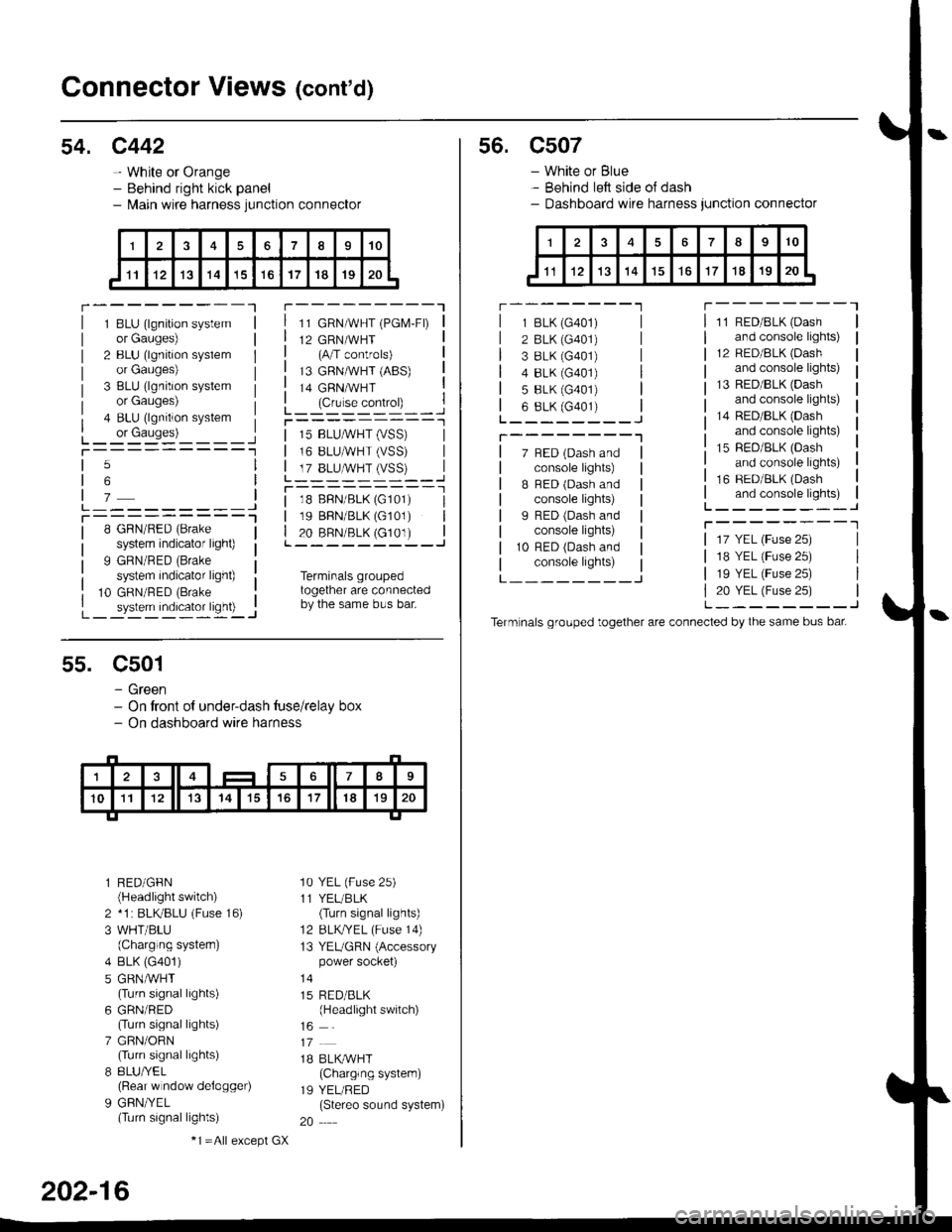
54. c442
- White or Orange- Behind right kick panel- l\,lain wire harness junction connector
r---------Tr---------"1
1 BLU (lgnition systemor Gauges)
2 BLU (lgnition syslemor Gauges)
3 BLU (lgnition systemor Gauges)
4 BLU (lgnition system
L_ or causes)L_-:-:::'-'�____Jt-----------1
11 GRN/WHT (PGM-FD
12 GRN/WHT(A/T controls)
13 GRNMHT (ABS)
14 GRNMHT
L_ lc,r'." .oIr"D_ _ _.jr----------_l
5
6
7L---------JT----------l8 GRN/RED (Brake
system indicator light)
9 GRN/RED (Brake
system indicator light)
10 GRN/RED (Brake
_ system indicator ligh0 -..1
| 15 BLUMHT (vSS) |I 16 BLUMHT (VSS) I
L T?_BLUSTrySS)--..]
l--------- - -l
| 18 BFN/BLK (G101) I| 19 BBN/BLK (G101) || 20 BRN/BLK (c101) |L---------J
Terminals groupedtogether are connectedby the same bus bar.
55. C501
- Green- On tront of under-dash tuse/relay box- On dashboard wire harness
l RED/GFN(Headlight switch)
2 *1 : BLKBLU (Fuse 16)
3 WHT/BLU(Charging systern)
4 BLK (G401)
5 GRNMHT(Turn signal lights)
6 GRN/RED(Turn signal lights)
7 GRN/ORN(Turn signal lights)
8 8LU/YEL(Rear w ndow delogger)
9 GFN/YEL(Turn signal lights)
'10 YEL (Fuse 25)
11 YEL/BLK(Turn signal lights)
12 BLKTYEL (Fuse 14)
13 YEUGRN (Accessorypower socket)
15 RED/BLK(Headlight switch)
1B BLK/WHT(Charglng system)
19 YEL/RED(Stereo sound system)
20
202-16
-1 =All e),cept GX
s6. c507
- White or Blue- Behind left side oJ dash- Dashboard wire harness junction connector
r --------'lT---------l
7 BED (Dash andconsole lights)
B BED (Dash andconsole lights)
I RED (Dash andconsole lights)
10 RFD (Dash andconsole lights)
11 RED/BLK (Dash
and console lights)
12 RED/8LK (Dash
and console lights)
13 RED/BLK {Dashand console lights)
14 RED/BLK (Dash
and console lights)
15 RED/BLK (Dash
and console lights)
16 RED/BLK (Dash
and console lights)L--------J
T--------T
L---_---_J
1 BLK (G401)
2 BLK (G401)
3 8LK {G401)4 8LK (G401)
5 BLK (G401)
6 8LK (G401)L________J
T--------"1
17 YEL (Fuse 25)
18 YEL (Fuse 25)
19 YEL (Fuse 25)
20 YEL (Fuse 25)L--------J
Term nals grouped together are connected by the same bus bat
Page 2127 of 2189
Connector Views (cont'd)
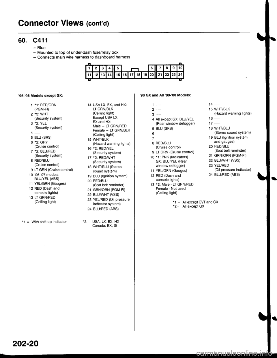
60. c411
- Blue- Mounted to top ol under-dash fuse/relay box- Connects main wire harness to dashboard harness
'95198 Models excepl GXI
1 *1: RED/GRN(PGrvr-FD
2 A2: WHT(Security system)
(Security system)
4
5 BLU (SRS)
6 *2r GRY(Cruise control)
7 *2: BLU/RED(Security system)
8 RED/BLU(Cruise control)
9 LT GRN (Cruise control)
10 '96-�97 models:BLU/YEL (ABS)
11 YEUGRN (Gauges)
12 RED (Dash andconsole lights)'13 LT GRN/RED(Ceiling light)
*1 = With shitt-up indicator
14 USA LX, EX, and HX:LT GRN/BLK
{Ceiling light)Except USA LX,EX and HX:ftrale - LT GRN/REDFemale - LT GRN/BLK(Ceiling light)
15 WHT/BLK(Hazard warning lights)
16 *2: RED|YEL(Security system)
17 *2: REDA/VHT(Security system)
18 WHT/BLU (Stereo
sound system)
19 BLU (lgnition system)
20 RED/BLU(Seat bett reminder)
21 GRN/OBN (PGN4 FD
22 BLUAVHT (VSS)
23 YEURED (Oil pressure
indicator system)
24 BLU/RED (ABS)
USA: LX: EX, HXCanadar EX, Si
202-20
'98 GX and All '99-'00 Models:
1
2
4 All except GX: BLU/YEL(Rear window defogger)
5 BLU (SRS)
7
B RED/BLU(Cruise control)
9 LT GRN {Cruise control)
10 *1: PNK (lnd cators)GX: BLU/YEL (Bear
window defo9ger)
1l YEL/GBN (Gauges)
12 RED (Dash andconsole lights)
13 *2: Male - LT GRN/REDFemale - Not used(Ceiling light)
14
15 WHT/BLK(Hazard warning lights)
18 WHT/BLU(Stereo sound system)
19 BLU (lgnition systemano gaugesl
20 RED/BLU(Seat bell reminder)
21 GRN/ORN (PG[,4-Fl)
22 BLU,ryVHT O/SS)23 YEURED(Oil pressure indicator)
24 BLU/RED (ABS)
*1 = Allexcept CW and GX*2= All except GX
Page 2131 of 2189
Gonnector Views (cont'd)
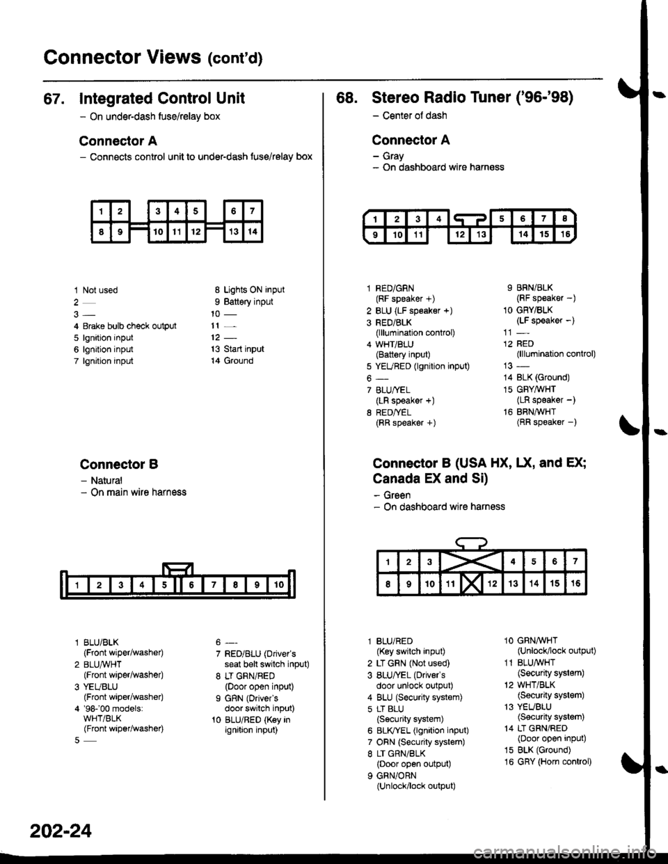
67. Integrated Control Unit
- On underdash fuse/relay box
Connector A
- Connects control unit to under-dash fuse/relay box
1 Not used
4 Erake bulb check output
5 lgnition input
6 lgnition input
7 lgnjtion input
Connectol B
- Natural- On main wire harness
l BLU/BLK
{Front wiper/washer)
2 BLUA/VHT(Front wiper/washe0
3 YEUBLU(Front wiper/washer)
4 '98-'00 models:WHT/BLK(Front wiper/washer)
8 Lights ON input
9 Battery input
11 _
13 Start input
14 Ground
7 RED/BLU (Driver's
seat b€lt switch input)
8 LT GRN/RED(Door open input)
I GRN (Oriver's
door switch input)'t0 BLU/RED (Key inignition input)
202-24
68. Stereo Radio Tuner ('96-'98)
- Center ot dash
Connector A
- Gray- On dashboard wire harness
1 RED/GRN(RF speaker +)
2 BLU (LF speaker +)
3 RED/BLK(lllumination control)
4 WHT/BLU(Battery input)
5 YEURED (lgnition input)
6-
7 BLU/YEL(LR speaker +)
8 RED/TEL(RR speaker +)
9 BRN/BLK(RF speaker -)
1O GRY/BLK(LF speaker -)
12 RED(lllumination control)
14 BLK (Ground)
15 GFY,4/VHT(LR speaker -)
16 BRNAVHT(RR speaker -)
Connector B (USA HX, UX, and EX;
Canada EX and Si)
- Green- On dashboard wire harness
l BLU/RED(Key switch input)
2 LT GRN (Not used)
3 BLU/'EL (Drivels
door unlock output)
4 BLU (Security system)
5 LT BLU
{Security system)
6 BLIVYEL (lgnition input)
7 ORN (Security system)
8 LT GRN/BLK(Door open output)
9 GRN/ORN(Unlock/lock output)
1O GRNAVHT(Unlock/lock output)
1 1 BLU/WHT(Security system)
'2 WHT/BLK(Security system)
13 YEUBLU(Security system)
14 LT GRN/RED(Door open input)
15 BLK (Ground)
16 GRY (Horn conkol)
Page 2141 of 2189
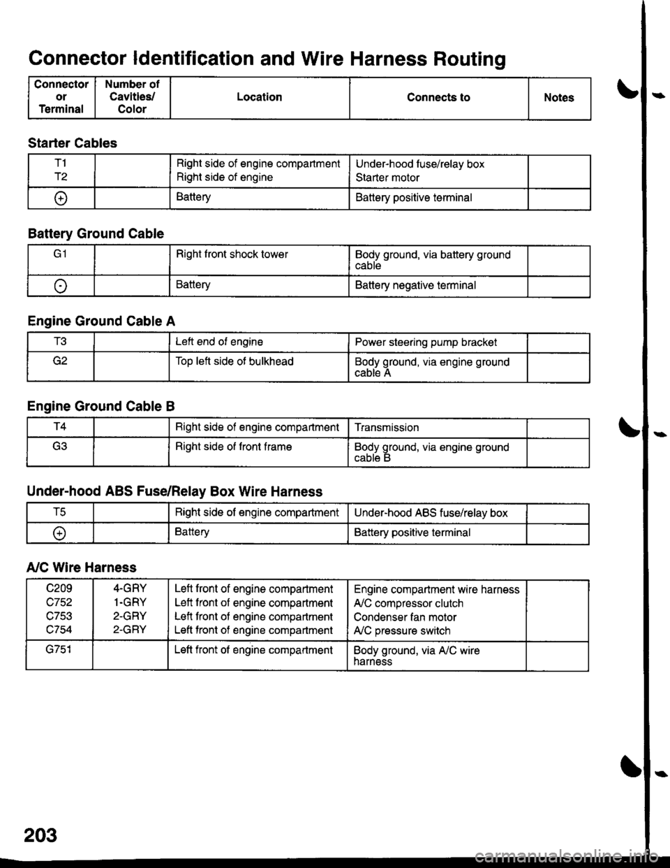
Connector ldentification and Wire Harness Routing
Connector
or
Terminal
Number of
Cavities/
Color
LocationConnects toNotes
Starter Cables
T1
r2
Right side of engine compartment
Right side of engine
Under-hood luse/relay box
Staner motor
t+lBatteryBattery positive terminal
Battery Ground Cable
Right front shock towerBody ground, via battery ground
cable
oBatteryBattery negative terminal
Engine Ground Cable A
t!tLeft end of enginePower steering pump bracket
Too left side ot bulkheadBody ground, via engine ground
cable A
Engine Ground Cable B
T4Bight side of engine compartmentTransmission
(ritRight side of front frameBody ground, via engine ground
Under-hood ABS Fuse/Relay Box Wire Harness
tcRight side of engine compartmentUnder-hood ABS fuse/relay box
oBatteryBattery positive terminal
A,/C Wire Harness
c209
wtJl/,\-7Ee
c754
4-GRY
1.GRY
2-GRY
2-GRY
Lefl front of engine compartment
Left front of engine compartment
Lefl front of engine compartment
Left tront of engine compartment
Engine compartment wire harness
A,/C compressor clutch
Condenser fan motor
A,/C pressure switch
G751Left front of engine compartmentBody ground, via A,/C wireharness
Page 2142 of 2189
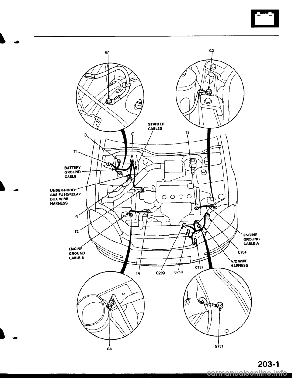
\..
STARTERCABLES
\..UNDER.HOODABS FUSE/RELAYBOX WIREHARNESS
BATTERYGROUNDcAELE
ENGINEGROUNDCAELE BA/C WIREHARNESS
)-
203-1
Page 2144 of 2189
Connector
or
Terminal
Number of
Cavitiesl
Color
LocationConnects toNotes
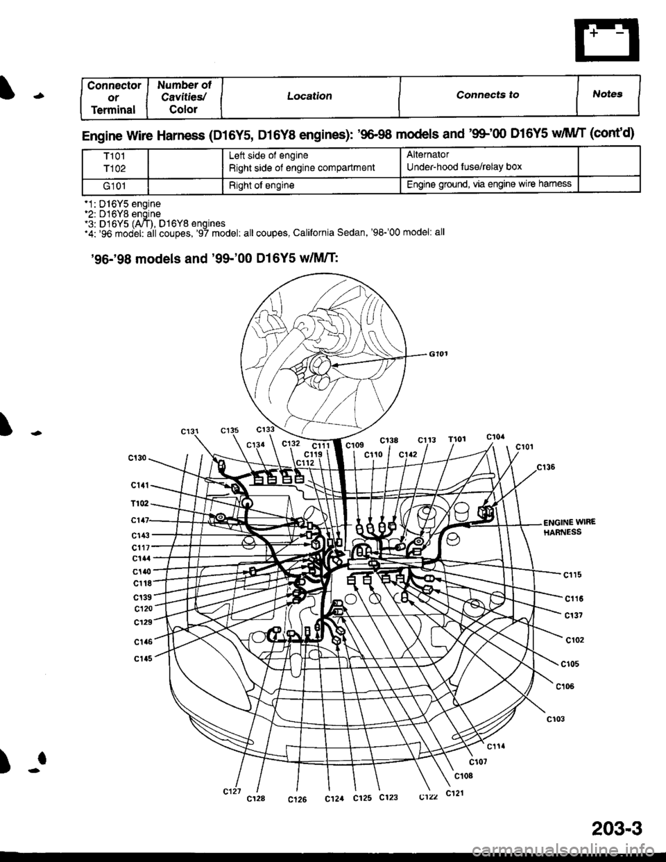
Engine Wire Harness (D16Y5, D16Y8 engines): '9&98 models and'9$'fl) D16Y5 dIWT (cont'd)
T101
r102
Lett side of engine
Right side of engine compartment
Alternator
Under-hood fuse/relay box
G101Right of engineEngine ground. via engine wire hamess
'1: D16Y5 engine.2: D16Yg engine'3: D16Y5 (A,/T). D16Y8 enoines'4: '96 model: dtl coupes,'97 model: all coupes, California Sedan,'98-'00 model: all
'96-'98 models and '99-'00 D16Y5 dM/T:
Ic138cl13 Tlorclllcr19 Ic109c110
c141.
T102.
c147-
cl4:t'
cl17'clal
c1|{)
cl18
c139
cl20
c129
c1a6
c1a5
€NGINE wlREHARNESS
cl l5
c116
c137
cr02
c105
c106
)-f
203-3
Page 2146 of 2189
\-
I.
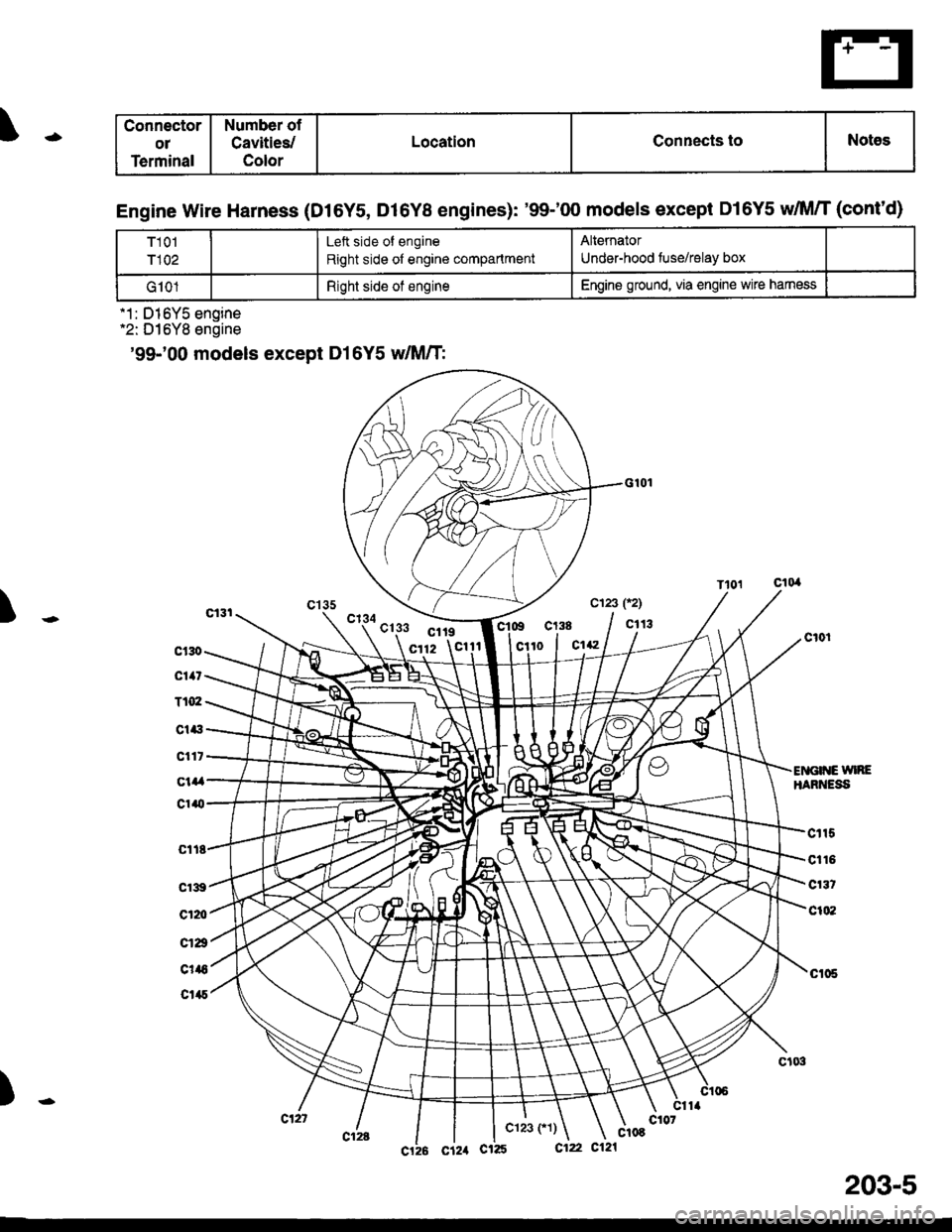
.1 : D16Y5 engine-2: D16Y8 engine
'99;00 models except Dl6Y5 w/M/T:
C134 -\-
c133 ctrg
c123 ('21
c112
cr0g
l.tto
cr38ct13
c130
Clilt
T102
Ctit3
cl17
G1a4
cltt
c139
ct20
c1?9
cr$
C1'15
Connector
ol
Terminal
Number of
Cavities/
Color
LocationConnects toNotos
Engine Wire Harness (Dl6Y5, D16Y8 engines): '99-'00 models except D16Y5 dM/T (cont'd)
T101
T102
Left side of engine
Right side oI engin€ compartment
Alternator
Under-hood tuse/relay box
G101Right side ot engineEngine ground. via engine wire hamess
)..
c1l5 C124 cl25 c1z2 c121
203-5
Page 2147 of 2189
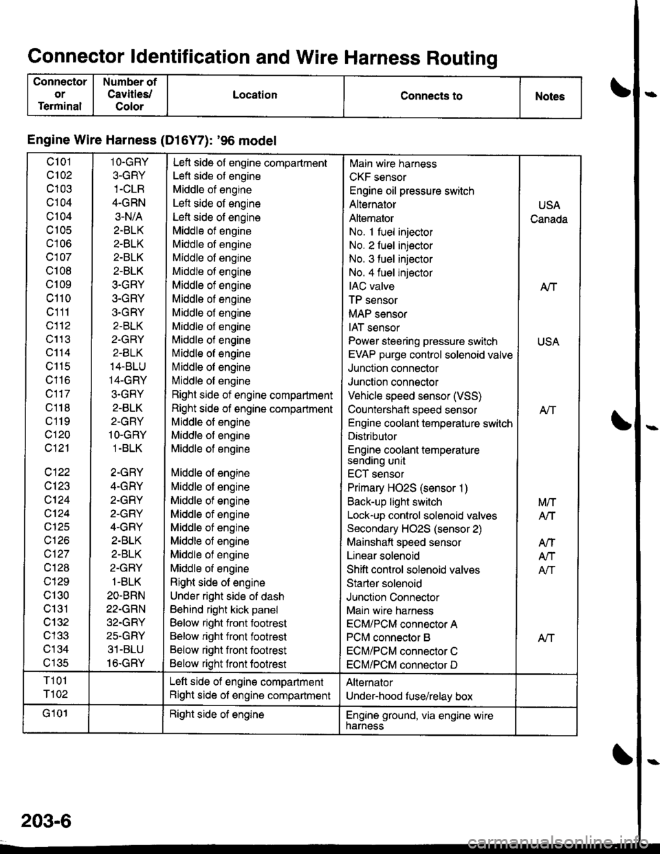
Connector ldentification and Wire Harness Routing
Connector
or
Terminal
Number of
Cavities/
Color
LocationConnects toNotes
Engine Wire Harness (Dl6Y7): '96 model
c101
c102
c103
cl04
c104
c 105
c106
c107
c108
c109
c110
c111
c112
c11 3
c114
c115
c116
c117
c118
c119
c120
c121
c122
c123
c124
cl24
c125
c126
c127
cl28
c129
c130
c131
cl32nl2?
c134al eR
1O.GRY
3-GRY
4.GRN
3-N/A
2.BLK
2-BLK
2-BLK
2-BLK
3.GRY
3-GRY
3.GRY
2-BLK
2.GRY
2-BLK
14-BLU
14-GRY
3.GRY
2.BLK
2-GRY
1O-GRY
1 -BLK
2-GRY
4.GRY
2.GRY
2-GRY
4-GRY
2.BLK
2-BLK
2-GRY
1-BLK
2O-BRN
22-GRN
32.GRY
25-GRY
31-BLU
16.GRY
Left side of engine compartment
Left side of engine
Middle of engine
Left side of engine
Lefl side of engine
Middle of engine
Middle of engine
Middle of engine
Middle of engine
Middle of engine
Middle of engine
Middle of engine
Middle of engine
Middle of engine
Middle of engine
Middle of engine
Middle of engine
Right side of engine compartment
Right side of engine compartment
Middle of engine
Middle of engine
Middle of engine
Middle of engine
Middle of engine
Middle of engine
Middle of engine
Middle of engine
Middle of engine
Middle of engine
Middle of engine
Right side of engine
Under right side of dash
Behind right kick panel
Below right front footrest
Below right front footrest
Below right front footrest
Below right front footrest
Main wire harness
CKF sensor
Engine oil pressure switch
Alternator
Altemator
No. 1 fuel injector
No. 2 fuel injector
No. 3 fuel injector
No. 4 fuel injector
IAC valve
TP sensor
MAP sensor
IAT sensor
Power steering pressure switch
EVAP purge control solenoid valve
Junction connector
Junction connector
Vehicle speed sensor (VSS)
Countershaft speed sensor
Engine coolant temperature switch
Distributor
Engine coolant temperaturesending unit
ECT sensor
Primary HO2S (sensor 1)
Back-up light switch
Lock-up control solenoid valves
Secondary HO2S (sensor 2)
Mainshaft speed sensor
Linear solenoid
Shift control solenoid valves
Starter solenoid
Junction Connector
Main wire harness
ECM/PCM connector A
PCM connector B
ECM/PCM connector C
ECM/PCM connector D
USA
Canada
A/T
USA
Atf
Aff
M/T
Arl
AtT
A/T
Afi
T101
T102
Left side of engine compartment
Right side of engine compartment
Alternator
Under-hood fuse/relay box
G101Right side of englneEngine ground, via engine wirenarness
203-6
Page 2149 of 2189
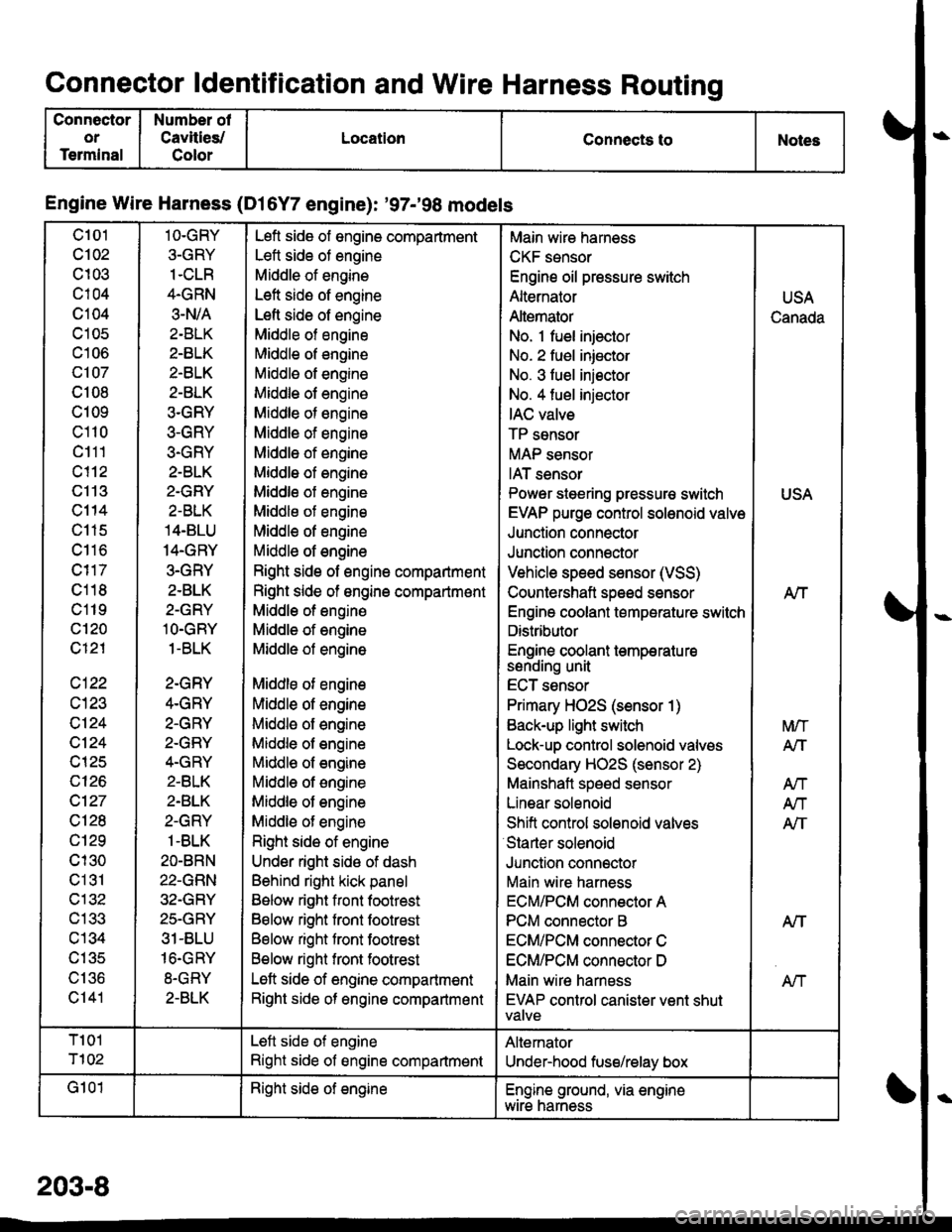
Connector ldentification and Wire Harness Routing
Connector
or
Terminal
Number of
Cavities/
Color
LocationConnects toNoles
Engine Wire Harness (Dl6Y7 engine): '97-'98 models
c101
c102
c103
c104
c104
c105
c106
c107
c108
c109
c110
c111
c113
c114
c115
c116
c118
c119
c'120
c121
c122
c124
c124
c125
c126
c127
c128
c129
cl30
c131
c132
c133
c134
c135
\, | 'tO
c141
1O-GRY
3-GRY
1.CLR
4.GRN
3.N/A
2-BLK
2-BLK
2-BLK
2-BLK
3.GRY
3-GRY
3-GRY
2-BLK
2.GRY
2-BLK
14.BLU
14.GRY
3.GRY
2-BLK
2-GRY
lO.GRY
1-BLK
2-GRY
4.GRY
2.GRY
2-GRY
4.GRY
2.BLK
2.BLK
2-GRY
1-BLK
2O-BRN
22-GRN
32-GRY
25.GRY
31-BLU
16.GRY
8-GRY
2-BLK
Lefl side of engine compartment
Lett side of engine
Middle of engine
Left side of engine
Lefl side of engine
Middle of engine
Middle of engine
Middle of engine
Middle of engine
Middle of engine
Middle of engine
Middle of engine
Middle of engine
Middle of engine
Middle of engine
Middle of engine
Middle of engine
Right side of engine compartment
Right side of ongine compartmont
Middle of engine
Middle of engine
Middle of engine
Middle of engine
Middle of engine
Middle of engine
Middle of engine
Middl€ of engine
Middle of engine
Middle of engine
Middle of engine
Right side of engine
Under right sido of dash
Behind right kick panel
Below right front footrest
Below right front footrest
Below right front footrest
Below right front footrest
Left side of engine compartment
Right side of engine compartmsnt
Main wire hamess
CKF sensor
Engine oil pressure switch
Alternator
Altemator
No. 1 fuel injector
No. 2 fuel iniector
No. 3 fuel iniector
No. 4 fuel injector
IAC valve
TP sensor
MAP sensor
IAT sensor
Power steering pressur€ switch
EVAP purge control solenoid valve
Junction connector
Junction connector
Vehicle speed sensor (VSS)
Countershaft speed sensor
Engine coolant temperature switch
Distributor
Engine coolant temperatu resenorng unI
ECT sensor
Primary HO2S (sensor 1)
Back-up light switch
Lock-up control solenoid valves
Secondary HO2S (sensor 2)
Mainshaft speed sensor
Linear solenoid
Shift conirol solenoid valves
Starter solenoid
Junclion connector
Main wire harness
ECM/PCM connector A
PCM connector B
ECM/PCM connector C
ECM/PCM connsctor D
Main wire harness
EVAP control canister vent shutVAIVE
USA
Canada
USA
Nf
A/T
M/T
A/T
Atl
An
AIT
NT
T101
T102
Left side of engine
Right side of engine compartment
Altemator
Under-hood fuse/relay box
G101Right side of engineEngine ground, via enginewtre narness
203-8