Iat sensor HONDA CIVIC 1998 6.G Owner's Guide
[x] Cancel search | Manufacturer: HONDA, Model Year: 1998, Model line: CIVIC, Model: HONDA CIVIC 1998 6.GPages: 2189, PDF Size: 69.39 MB
Page 393 of 2189
PGM-FI System
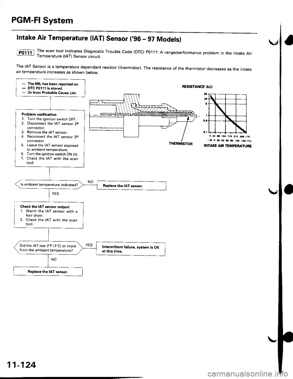
Intake Air Temperature (lAT) Sensor ('96 - 97 Models)
The scan tool indicates Diagnostic Trouble code (DTC) P0111: A range/performance problem in the lntake AarTemperature (lAT) Sensor circuit.
The IAT sensor is a temperature dependant resistor (thermistor). The resistance of the thermistor decreases as the intakeair temperature increases as shown below.
RES|STAI{CE {tol
. 32 .. ro. tr. 2r, zaa r..l-20 o 20 /|o ao ao 100 rrotlcl
INTAIG AIR TEMPEMTURE
- The MIL hss beon reported on.- DTC P0111 is stored.- Or from Probable C.use List.
Problem verification:1. Turn the ignition switch OFF.2. Disconnect the IAT sensor 2Pconnector,3. Remove the IAT sensor.4. Reconnect the IAT sensor 2p
5. Leave the IAT sensor exposedto ambaent temperature,6. Turn the ignition switch oN fll).7. Check the IAT with the scantool.
Rsplscg the IAT sensor.
Check tho IAT sensor output:1. Warm the IAT sensor with ahair dryer-2. Check the IAT with the scantool.
Did the IAT rise 2"F (1.C) or morefrom the ambient temperature?Int€rmittont failu.e, system is OKat this time.
Replsce the IAT sensor.
11-124
Page 394 of 2189
IIntake Air Temperature (lATl Sensor
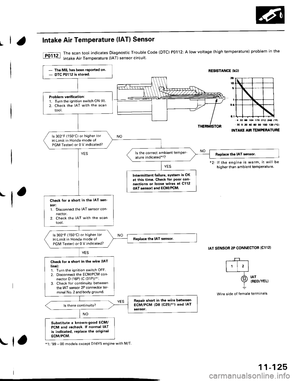
The scan tool indicates Diagnostic Trouble Code {DTC) P0112: A low voltage (high temperature) problem in the
lntake Air Temperature (lAT) sensor circuit.
RESISTANCE IKOI
.-l
*2: lf the engine is warm, it will be
higher than ambient temPerature.
IAT SENSOR 2P CONNECTOR {C112)
. a2 .. toa rra rrl l:rt t.al20 0 20 ro ao ao too t2ot.cl
INTAXIE AIR TEMPEFATURE
IAT{RED/YEL)
termrnars
-+-r
I'l'l-_T-
I=
Wire side of female
The MIL has been Teported on.
DTC P0112 is stored.
Problem verification:1. Turnthe ignition switch ON 1ll)2. Check the IAT with the scan
tool-
ls 302'F (150"C) or hagher (or
H Limit in Honda mode ot
PGM Tester) or 0 V indicated?
ls the correct ambrent temper
ature indicatedi'�?Roolac€ tho IAT 3ensor.
lntermittent failure, svstom is OK
6t this tim€. Check for Poor Gon-
nections or loos€ wires st C112
{lAT.en3orl and ECM/PCM.
Check tor a shon in the IAT sen-
sor:1. Disconnect the IAT sensor con
nector.2. Check the IAT with the scan
tool.
ls 302"F (150'C)or higher (or
H'Limit in Honda mode of
PGM Tester) or 0 V indicated?
Ch6ck for s short in the wira (lAT
lin€):1. Turn the ignition switch OFF
2. Disconnect the ECM/PCM con-
nector D (16P) (C (31P))*'.
3. Check for continuity between
the IAT sensor 2P connector ler-
minal No. 2 and body ground.
Reoair short in the wire bstweenECM/PCM tD8 (c25)'1) and IAT
Substitute a known-good ECM/
PCM and recheck. It normel IAT
is indicated, replace the original
ECM/PCM.
* l: '99 - 0O models except Dl6Y5 engine with M/T-rf,
11-125
Page 395 of 2189
PGM-FI System
Intake Air Temperature (lAT) Sensor
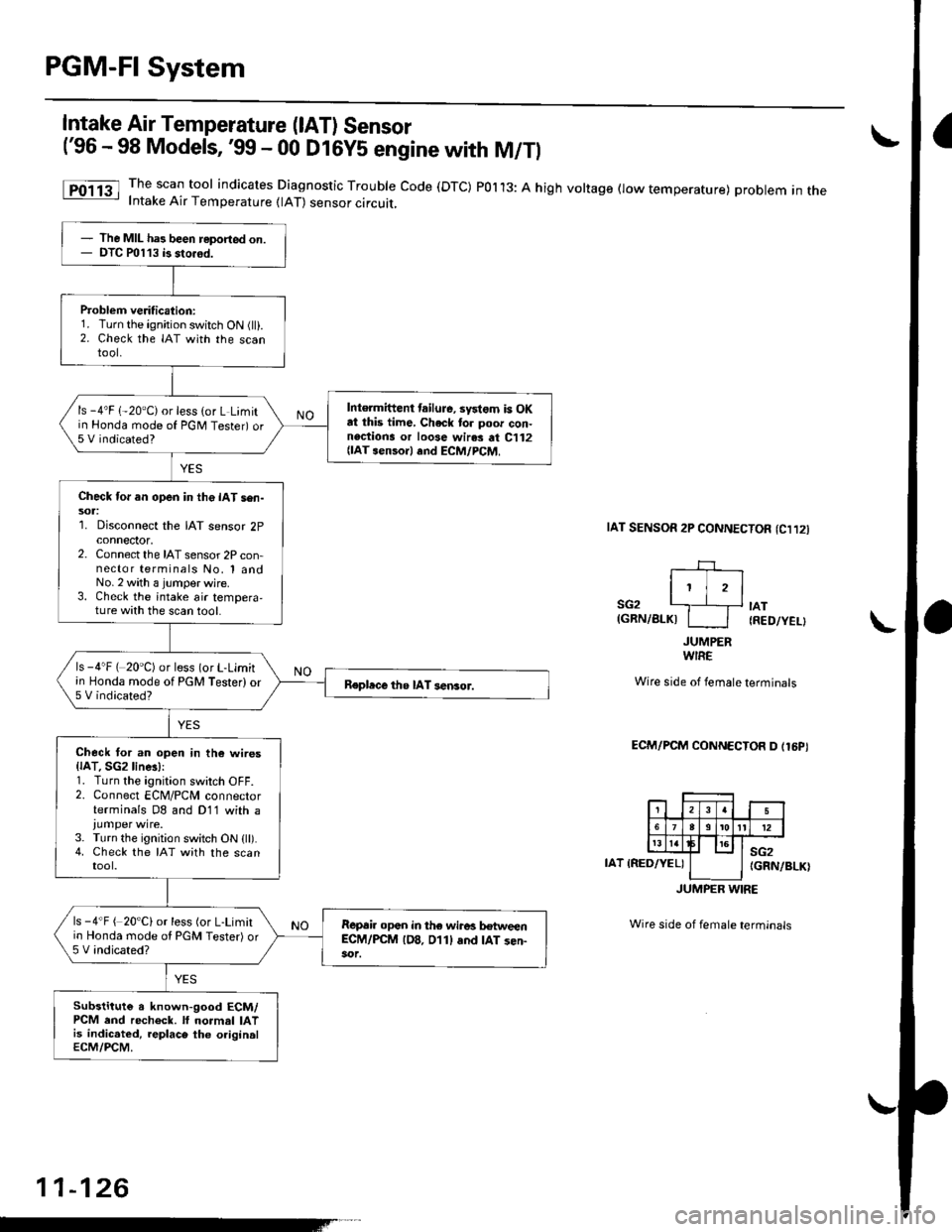
('96 - 98 Models,'99 - 00 D16Y5 engine with M/Tl
11-126
The scan tool indicates Diagnostic Trouble Code (DTC) POl13: A high voltage flow temperature) problem in theIntake Air Temperature (lAT) sensor circuit,
taT sENsoR 2P CONNECTOn (Cl12l
I' jrl
SG2 '---.]__+ tAT(GRN/BLKI I I IRED/YEL}
JUMPERWIRE
Wire side of female terminals
ECM/PCM CONNECTOR D (16PI
IAT IRED/YEL)sG2(GRN/BLK)
JUMPER WIRE
Wire side of female terminals
The MIL has been reported on.DTC P0113 b sto.6d.
Problem veritication:1. Turn the ignition switch ON (ll).2. Check the IAT with the scantool.
Intermittent tailuJe, systom is OKat this time, Check to. poor con-nections or loose wir.s at C112{lAT senso.l .nd ECM/PCM,
ls -4'F 1-20"C) or less (or L Limitin Honda mode of PGNI Tester) or5 V indicated?
Check for an open in the IAT sen-sol:1. Disconnect the IAT sensor 2pconnector,2. Connect the IAT sensor 2P con-nector terminals No, 1 andNo.2 with a jumper wjre.3. Check the intake air tempera,ture with the scan tool.
ls -4"F ( 20'C) or less (or L-Limitin Honda mode of PGM Tester) or5 V indicated?Repbce the IAT sensor.
Check tor an open in th6 wires{lAT. SGzline!):1. Turn the ignition switch OFF.2. Connect ECM/PCM connectorterminals D8 and D11 with a
3. Turn the ignition switch ON (ll).4. Check the IAT with the scantool.
ls -4"F ( 20'C) or less (or L-Limitio Honda mode ol PGM Tester) or5 V indicated?
R€p6ir opan in the wiro! hweenEC-M/PCM lD8. 011l and IAT sen-
Substitute a known-good ECM/PCM end recheck. lf normal IATis indic.ted, replace the originalECM/PCM.
Page 396 of 2189
L
I
Intake Air Temperature (lAT) Sensor
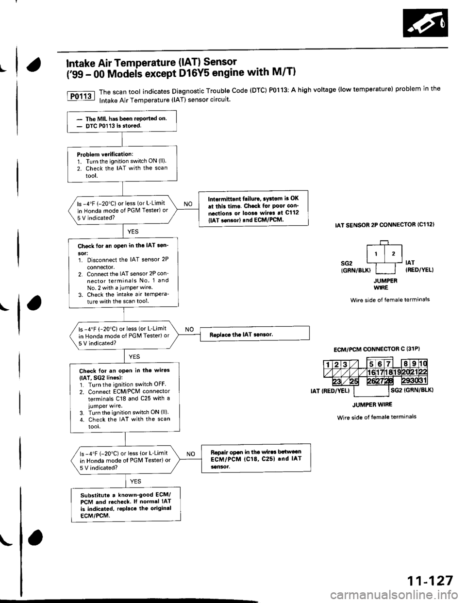
('99 - 00 Modeis except D16Y5 engine with M/Tl
The scan tool indicates Diagnostic Trouble code (DTC) P0113: A high voltage (low temperature) problem in the
Intake Air Temperature (lAT) sensor circuit.
IAT SENSOR 2P CONNECTOB IC112'
r-+-r
It l,lsG2 L1__f lAr
IGRN/BLK} I I (RED/YELI
JUMPERWIRE
Wire side of female terminals
Wire side of lemale terminals
The MIL has be€n rePorted on.
DTC P0113 i3 stored.
Probl€m vetification:1. Turn the ignition switch ON (ll).
2. Check the IAT with the scan
tool.
Intormittont f.iluro, tyrtom i. OK
.t thi! tim.. Chocl for Poor con'
nactions or looso wit6 !t C112
tlAT ..n!or) rnd ECM/PCftl,
ls -4"F (-20"C) or less (or L-Limit
in Honda mode of PGM Tester) or
5 V indicated?
Check tor an open in tho IAT son'
304:1. Disconnect the IAT sensor 2P
connector,2. Connect the IAT sensor 2P con_
nector terminals No. 1 and
No.2 with a jumPerwire.
3. Check the intake air tempera-
ture with the scan tool.
ls -4"F {-20"C) or less (or L-Limit
in Honda mode of PGM Tester) or
5 V indicated?
Check lor an open in iho wirg3
{lAT, SG2 linesl;1. Turn the ignition switch OFF
2. Connect ECM/PCM connector
terminals C18 and C25 with a
iumper wire.3. Turn the ignition switch ON (ll)
4. check the IAT with the scan
tool.
Roprir opan in tho wilaa brlwocn
ECM/PCM (C18, C25l .nd IAT
!on30r.
ls -4"F (-20"C) or less (or L-Limit
in Honda mode oI PGM Testerlor
5V indicated?
substituts a known'good ECM/
PCM and recheck. ll normal IAT
is indicated, replace the otiginal
ECM/PCM.
ECM/PCM CONNECTOR C (31PI
JUMPER WIRE
11-127
Page 397 of 2189
PGM-FI System
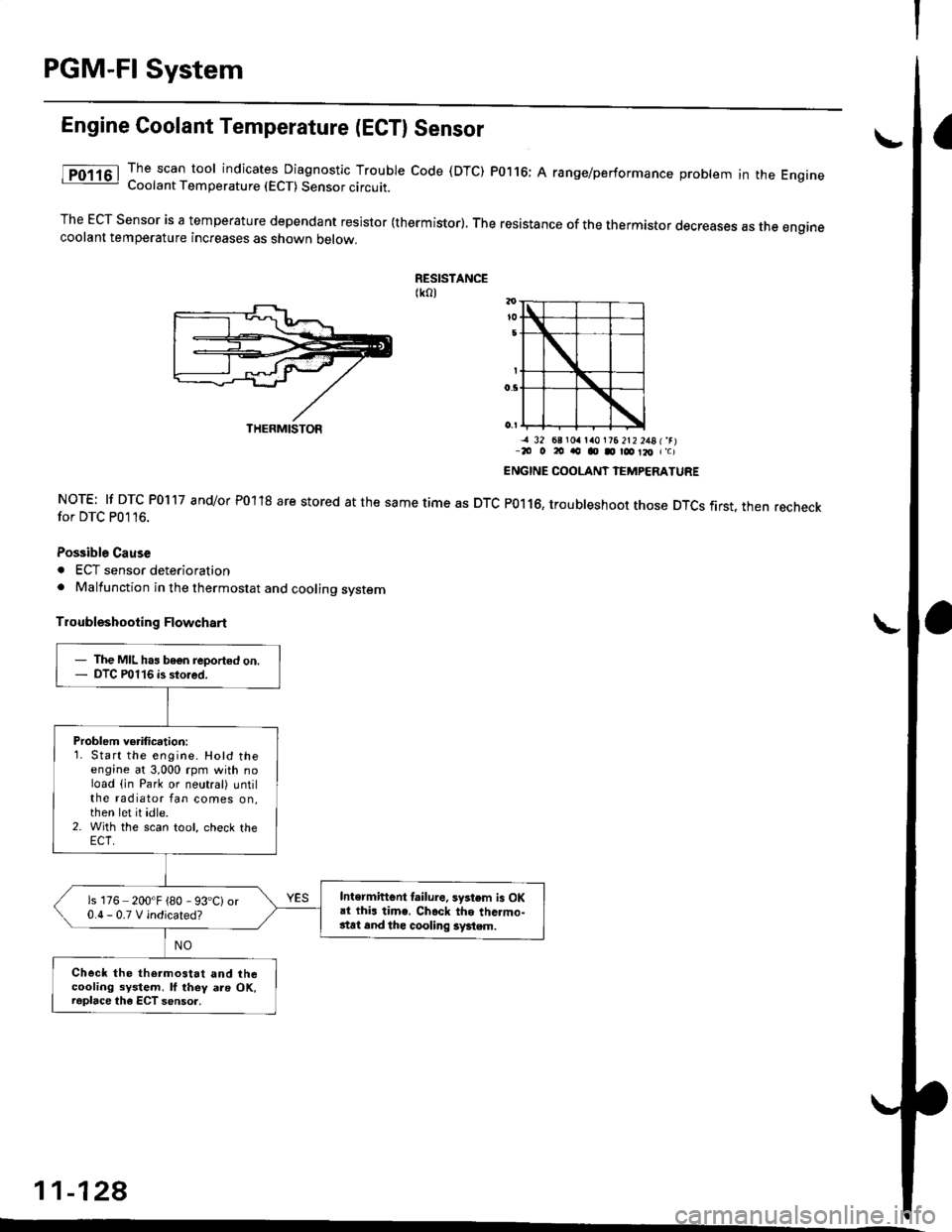
Engine Coolant Temperature (ECTI Sensor
The scan tool indicates Diagnostic Trouble code (DTC) P0116; A range/performance problem in the EngrneCoolant Temperature (ECT) Sensor circuit.
The ECT Sensor is a temperature dependant resistor (thermistor). The resistance of the thermistor decreases as the enginecoolant temperature increases as shown oetow.
RESISTANCE(ko)
NOTE: lf DTC P0117 and/or P01'18 are stored at the same time as DTCfor DTC P0116.
Possible Cause
. ECT sensor deterioration. Malfunction in the thermostat and cooling system
Troubleshooting Flowchart
-a 32 68 r0a la0l?6 2t2 2481'rr-20 o 20 ao o D r@ Il, r'c)
ENGINE COOLANT IEMPERATURE
P0116, troubleshoot those DTCS first. then recheck
11-128
THERMISTOR
- The MIL has bogn reported on.- DTC P0116 is stored.
Problem verification:1. Start the engine. Hotd theengine at 3,000 rpm with noload (in Park or neutral) untilthe radiator fan comes on,then let it idle.2. With the scan tool, check the
Intermiftent lailure. system is OKai thi. time. Ch.ck the thc.mo-stat 6nd thc cooling system.
is 176 200'F {80 - 93'C)or0.0-0.TVindicated?
Check the thermostat and thecooling system. ll they als OK,raplace the ECT sensor.
Page 403 of 2189
PGM-FI System
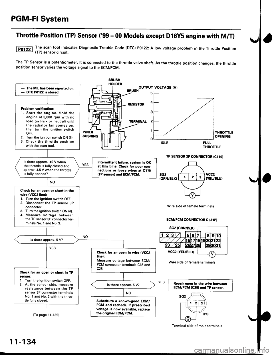
Throttle Position (TPl Sensor ('99 - 00 Models except D16Y5 engine with M/T)
lTO12Z _TI scan tool indicates Diaqnosttc Trouble Code (DTC) P0122: A low voltage problem in the Throttle position- { | r, sensoa crrcurl.
The TP Sensor is a potantiometer. lt is connected to the throttle valve shaft. As the throttle position changes, the throttleposition sensor varies the voltage signal to the ECM/PCM.
ERUSHHOI.DENOUTPUT VOLTAGE (VIBRUSH
BESIS?OF
TERi'I AL
5
4
3
2
1
o
INNERBUS}IINGTHROTTLEOPE II{G
FULLTHROTTLE
TP SENSOR 3P CONNECTOR {Cl1OI
sG2IGRN/8LKIvcc2(YEUBLUI
Wire side of temale terminals
ECM/PCM OONNECTOR C 131P)
Ch.Gk for rn opan or 3hort in TP36nlot:1. Turn the ignition switch OFF.2, At the sensor side, moasureresistance between the TPsensor 3P connector terminalsNo. 1 and No. 2 with th€ throt,tle fully closed.
(To page 11-135)
- Th. MIL har boon.6portcd on.- DTC P0122 b siored.
Problem verification:1. Start the engine, Hold theengine at 3,000 rpm with noload (in Park or neutral) untilthe radiator fan comes on.then turn the ignition switchOFF,2. Turn the ignition switch ON (ll).3. Check the throttle positionwith the scan tool.
ls there approx. .49 V whenthe throttle is fully clos€d andapprox, 4.5 V when the throttleis fully opened?
l||t rmittont failura, lyrtom b OKat thi! tima. Chock tor poor con-nactionr o. looao wires rt C110{TP 3.n!or} rnd ECM/PCM.
Check for an opan or 3hort in thowi.c (VCC2 linc):1. Turn the ignition switch OFF.2. Disconnect the TP sensor 3Pconnector,3. Turn the ignition switch ON (ll).4. Measure voltago betweenthe TP sensor 3P connector terminals No. 1 and No.3.
ls thero approx. 5 V?
Chccl tor .n opln in wiro IVCC2lin€l:Mgasure voltago between ECM/PCM connector terminals C18 and
R.prir opcn in the wiro bctw.enECM/PCM (C281 and TP 3€nror.ls there approx. 5 V?
Subrtituto r known-good ECM/PCM .nd rochcck. lf pro.c.ibedvoltaga i! now available, roplacotho origin.l ECM/PCM.
Wire side ol female terminrls
Terminal side of male terminals
11-134
L
Page 406 of 2189
I
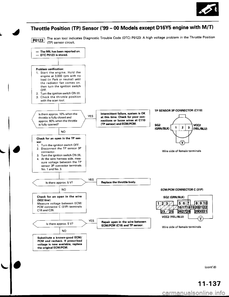
Throttle Position (TP) Sensor ('�99 - 00 Models except D16Y5 engine with M/Tl
The scan tool indicates Diagnostic Trouble Code {DTC) P0123: A high voltage problem in the Throftle Position
{TP) sensor circuit.
TP SENSOR 3P CONNECTOR {C11OI
sG2{GRN/BLKIvoc2
{YEUBLU}
'l'Wire side of female term;nals
ECM/PCM CONNECTOR C (31PI
Wire side of femal€ terminals
(cont'd)
11-137
The MIL has been reported on
DTC P0123 is slored.
Problem verification:1. Start the engine. Hold the
engine at 3,000 rpm with no
load (in Park or neutral) until
the radiator fan comes on
then turn the ignition swatch
OFF,2. Turn the;gnition switch ON (ll).
3. Check the throttle Positionwith the scan tool.
lntormittenl tailure, 3ystom is OK
at this time. Check tor Poor con'
neqtions or loo3€ wires at C'110(TP sensorl tnd ECM/PCM.
ls there approx. 10% when the
throttle is fully closed and
approx. 90% when the throttleis fully opened?
Ch€ck for an open in the TP s6n-
soJ:1. Turn the ignition switch OFF.
2. Disconnect the TP sensor 3P
3. Turn the ignition switch ON (ll).
4. At the wire harness side, mea-
sure voltage between the TP
sensor 3P connector terminalsNo. 1 and No.3.
ls there approx. 5 V?
Check tor an open in the wire(SG2lino):
Measure voltage between ECM/
PCM connector C (31Pi terminals
C18 and C28.
Repair open in the wite betwe€nECM/PCM (Cl81and TP son.or.ls there approx. 5 V?
Substitute a known-good ECM/PCM and recheck. lf Pr$cribedvoltage is now aveilabl6. replacethe original ECM/PCM.
Page 408 of 2189
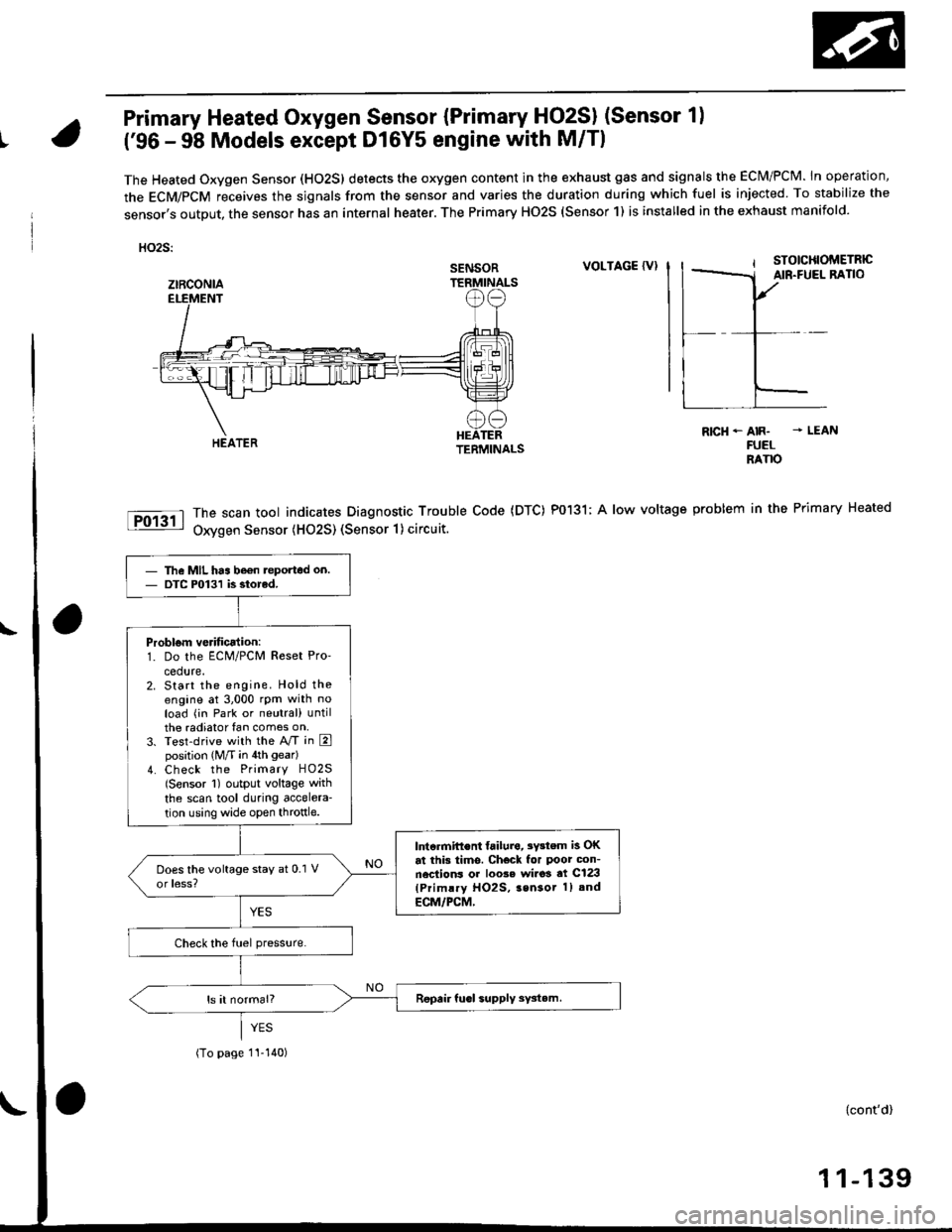
Primary Heated Oxygen Sensor {Primary HO2SI (Sensor 1)
t('96 - 98 Models except Dl6Y5 engine with M/Tl
The Heated Oxygen Sensor (HO2S) detects the oxygen content in the exhaust gas and signals the ECM/PCM. In operation,
the ECM/PCM receives the sjgnals from the sensor and varies the duration during which fuel is injected To stabilize the
sensor,s output, the sensor has an internal heater. The Primary HO2S (Sensor 1) is installed in the exhaust manifold.
HO2S:
VOLTAGE {VI
The scan tool indicates Diagnostic Trouble Code (DTC) P0131; A low voltage
Oxygen Sensor (H02S) (Sensor 1) circuit.
R|cH-AIR- - LEANFUELRANO
problem in the Primary Heated
SENSOR
ztRcoNlA
The MIL has be€n teported on.DTC P0131 is siorcd.
Problom verificalion:1. Do the ECM/PCM Reset Pro'
cedure.2. Start the engine. Hold theengine at 3,000 rpm with noload (in Park or neutral) untilthe radiator fan comes on,3. Test-drive with the A/T in Eposition (M/T in 4th gear)
4. Check the Primary HO2S(Sensor 1) output voltage with
the scan tool during accelera-
tion using wide open throttle.
lntcrmift€nt failura, 3Y3tem is OKat this tims. Check for Poor con-nections or loo3e wi.o3 at C123(Primlry HO2S, 3sn3or 1) and
ECM/PCM,
(To page 1I-140)
{cont'd)
1 1-139
Page 410 of 2189
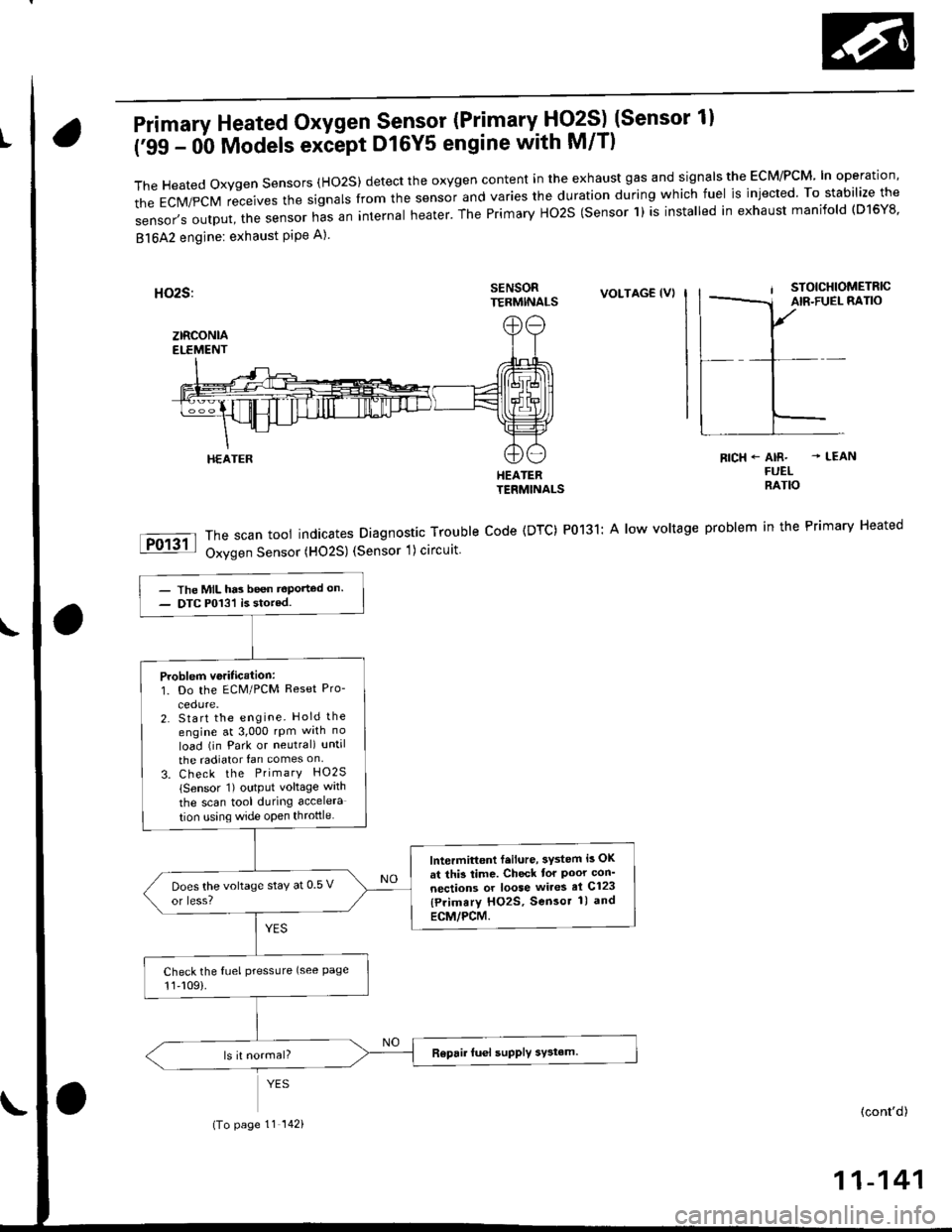
Primary Heated Oxygen Sensor (Primary- Fjq?S) (Sensor 1l
('99 - 0b Models exiept D16Y5 engine with M/T)
TheHeatedoxygensensors(Ho2S)detecttheoxygencontentintheexhaustgasandsigna|stheEcM/PcM'|noperation,
the EcM/pcM receives the signars from the sensor and varies the duration during which fuel is injected. To stabilize the
sensor,soutput,thesensornasaninternaIheater.ThePrimaryHo2S(sensorl)isinsta|ledinexhaustmanifo|d(D16Y8.
81642 engine: exhaust PiPe A)
SENSORTERMINALSVOLTAG€ (VI
HEATERTERMINALS
The scan tool indicates Diagnostic Trouble Code (DTC) P0131: A low voltage
Oxygen Sensor (HO2S) (Sensor 1) circuit
RICH+ AIR- - LEANFUELRATIO
problem in the Primary Heated
HEATER
- The MIL has been t€Ported on.- DTC P013'l is stored.
Problem veritication:1. Do the ECM/PCM Reset Pro-
2. Start the engine. Hold the
engine at 3,000 rpm wrth no
load (in Park or neutral) until
the radiator fan comes on
3. Check the PrimarY HO2S
lSensor 1) output voltage wath
the scan tool during accelera
tion using wide open throttle
lntermittont f.ilure, 3ystem i3 OK
at thi3 time. Check tor Poor con'
nections or loose wires el C123
{Primary HO2S, Sensor 1) and
ECM/PCM.
Does the voltage stay at 0 5 v
or less?
Check the fuel pressLlre (see Page11,109).
(To page 11 142)(cont'd)
11-141
Page 412 of 2189
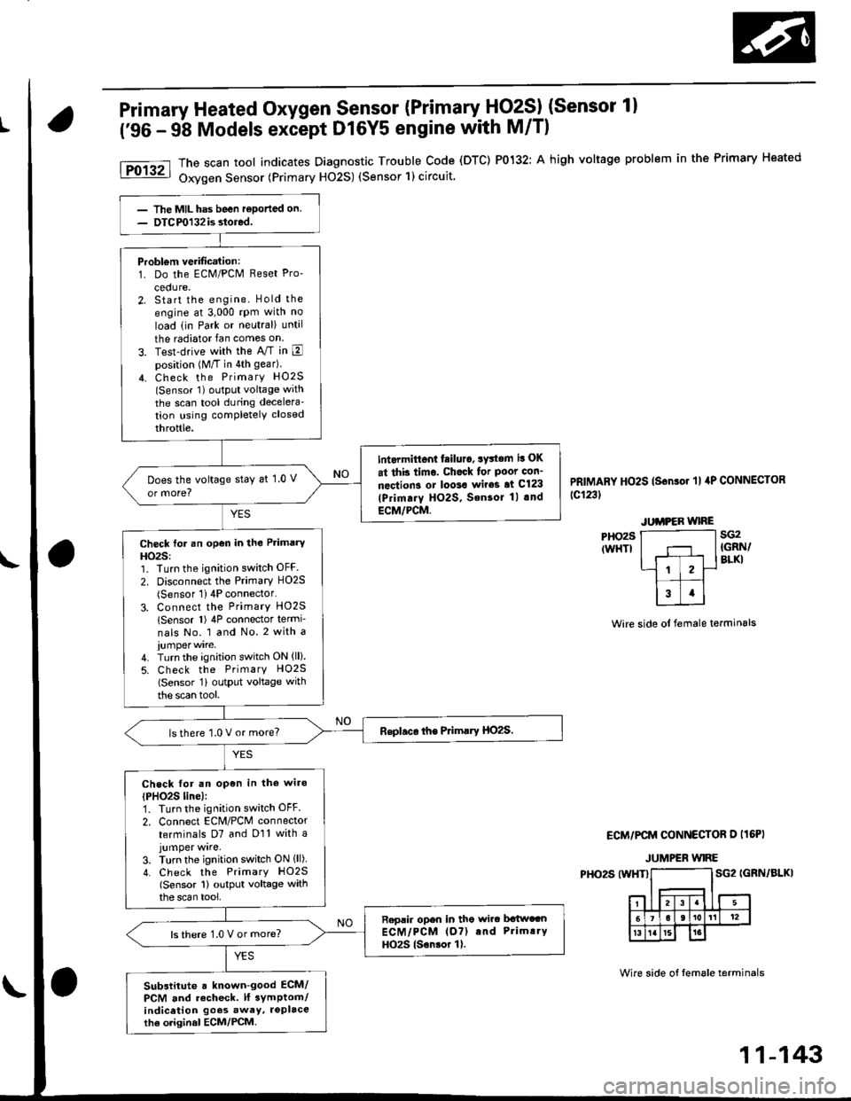
Primary Heated Oxygen Sensor (Primary HO2SI (Sensor 1)
('96 - 9b Models except Dl6Y5 engine with M/Tl
PHO29IWHT}
The scan tool indicates Diagnostic Trouble Code (DTC) P0132: A high voltage problem in the Primary Heated
Oxygen Sensor (Primary H02S) (Sensor'l) circuit.
PRIMARY HO2S (Sonso. 'll 4P CONNECToR
tc123t
sG2IGRN/BLKI
Wire side ot female terminals
ECM/PCM CONNECTOR D I16PI
JUMPER WIRE
PHO2S (WHT}SG2 IGRN/BLKI
Wire side of tem6le terminals
Probl€m verification:1. Do the ECM/PCM Reset Pro-
cedure.2. Start the engine. Hold the
engine at 3,000 rpm with no
load (in Park or neutral) until
the radiator fan comes on
3. Test-drive with the A/T in Eposition (M/T in 4th gear)
4. Check the PrimarY HO2S(Sensor 1) oLltPut voltage with
the scan tool during decelera'tion using completely closed
throttle.
Int.rmittont fiilur., system it OK
at thb timo. Chock for Poot con-
nections or loo3a wir63 at Cl23
lPrimarY HO2S, SensoJ 1l .nd
ECM/PCM.
Does the voltage stay at 1.0 V
or more?
Check for an open in the Primary
HO2S:1. Turn the ignition switch OFF.
2. Disconnect the Primary HO2S(Sensor 1) 4P connector'
3. Connect the PrimarY HO25
lSensor l) 4P connector termi-
nals No. 1 and No. 2 with a
4. Turn the ignition switch ON (ll).
5. Check the PrimarY H02S(Sensor 1i outPut voltage with
the scan tool.
lsthere 1.0 V or more?
Check for an open in the wiro
{PHO2S line):1. Turn the ignition switch OFF.
2. Connect EcM/PcM connector
terminals D7 and D11 with ajumper wrre,3. Turn the ignition switch ON lll)4. Check the PrimarY HO2S(Sensor 1) output voltage withthe scan tool,
Replir open in tho wirc b€twccnECM/PCM lo?) and Prim!.Y
HO2S lsonsor 1).ls there 1.0 V or more?
Substitute a known-good ECM/PCM and recheck. lf 3ymptom/indicetion goos awey, roplacethe oliginal ECM/PCM.
11-143