dashboard light HONDA CIVIC 1998 6.G Owner's Guide
[x] Cancel search | Manufacturer: HONDA, Model Year: 1998, Model line: CIVIC, Model: HONDA CIVIC 1998 6.GPages: 2189, PDF Size: 69.39 MB
Page 1786 of 2189
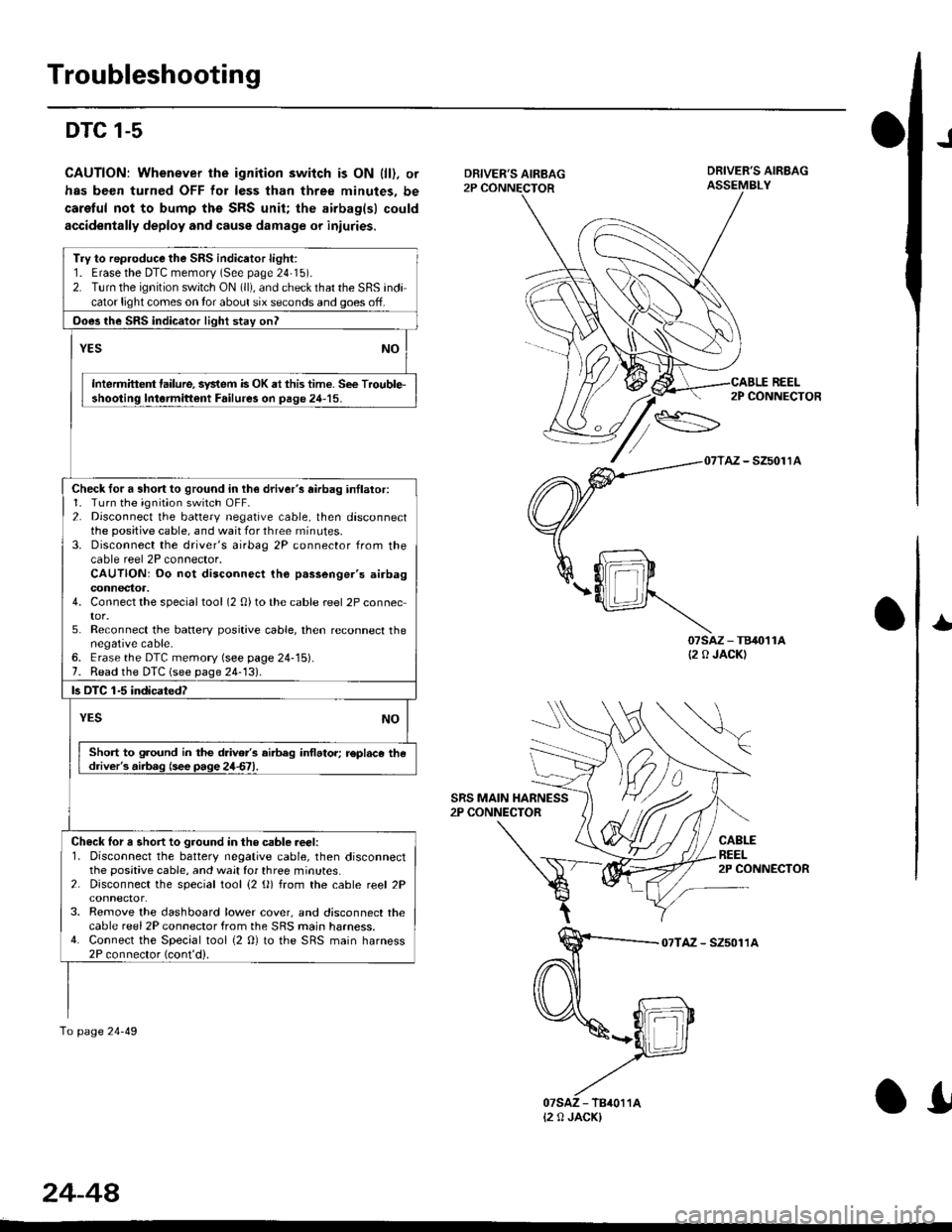
Troubleshooting
DTC 1-5
CAUTION: Whenever the ignition switch is ON {ll). or
has been turned OFF for less than three minutes, be
caretul not to bump ths SRS unit; the airbag(sl could
accidentally deploy and cause damage or iniuries.
J
DRIVER'S AIRBAG2P CONNECTOR
SRS MAIN HARNESS2P CONNECTOR
DRIVER'S AIRBAGASSEMBLY
REEL
07sAz - TB40't1A(2 0 JACK)
2P CONNECTOR
AZ - SZ5011A
CABLEREEL2P CONNECTOR
I
07TAZ - SZ5011A
Try to rep.oduce the SRS indicator light:1. Erasethe DTC memorv (See page 24'15).2. Turn the ignition switch ON (ll), and check that the SRS indicator light comes on tor about six seconds and goes off.
Ooes the SRS indicator light stay onl
YESNO
Intermittent lailure, system is OK at this time. See Trouble-shooting lntormittent Failure3 on page 24-15.
Check for a short to ground in lh€ driver's airbag inllator:1. Turn the ignition switch OFF.2. Disconnect the battery negative cable, then disconnectthe positive cable, and wait for three rninutes.3. Disconnect the driver's airbag 2P connector from thecable reel 2P connector.CAUTION: Do not disconnect tho p.ssenger's airbagconnectoa.4. Connect the specialtool (2 0)to the cable reel 2P connector.5. Reconnect the batlery positive cable, then reconnect thenegative cable-6. Erase the DTC memory (see page 24-15).7. Read the DTC (see page 24-131.
ls OTC 1-5 indicatedT
YESNO
Short to ground in the drive/s airbeg inflator; r€pl.ce thedriver's.iib.g (see page 24d1.
Check lor a short to ground in the csble reer:l. Disconnect the battery negative cable, then disconnectthe positive cable, and wait for three minutes.2. Disconnect the special tool {2 (}) from the cable reel 2P
3. Remove the dashboard lower cover, and disconnect thecable reel 2P connector from the SRS main harness.4. Connect the Special tool {2 0} to the SRS main harness2P connector (cont'd).
To page 24-49
{2 0 JACK)
24-44
.I
Page 1813 of 2189
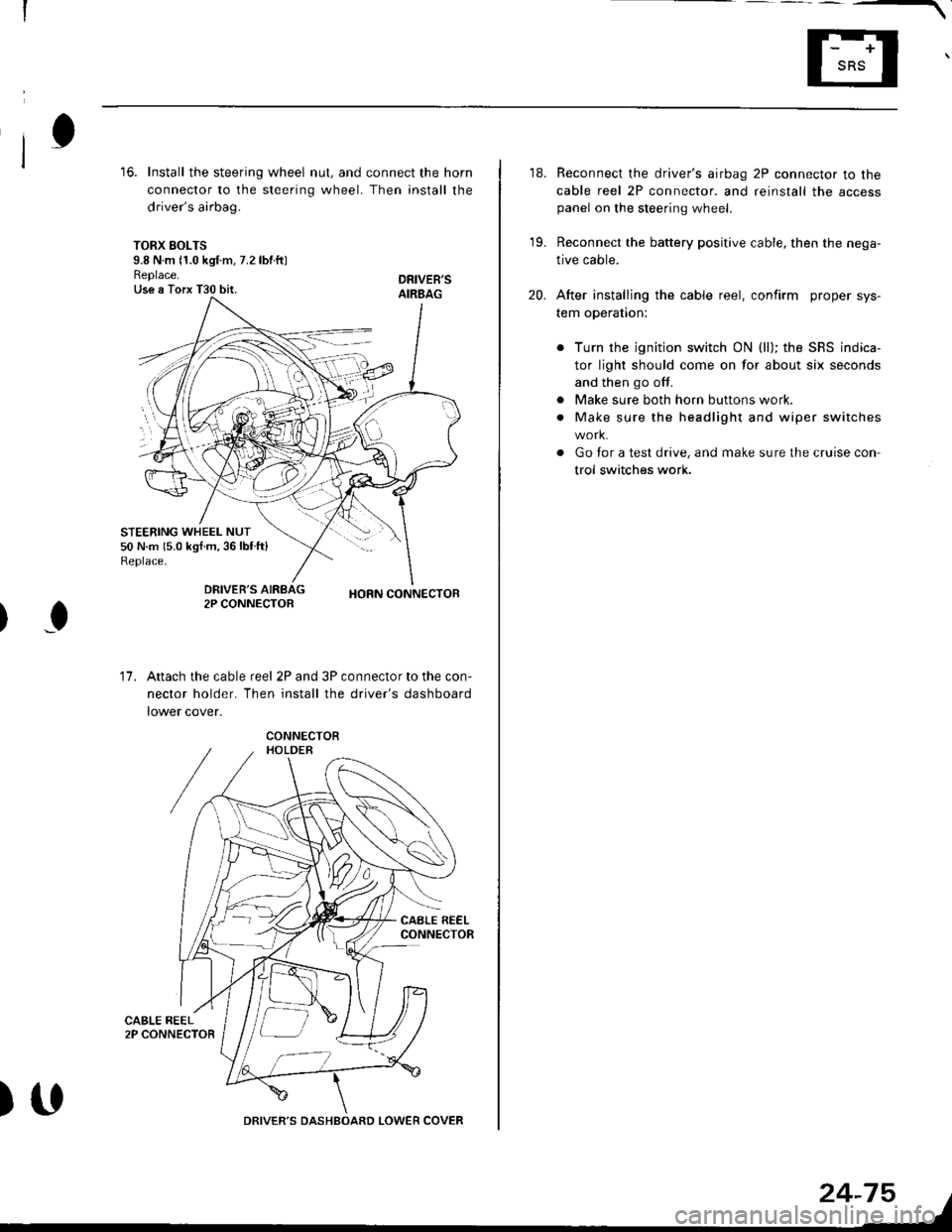
16. Install the steering wheel nut, and connect the horn
connector to the steering wheel. Then install the
driver's airbag.
TORX SOLTS9.8 N m 11.0 kgf m, 7.2 lbtftlReplace.Use a Torx T30 bit.
STEERING WHEEL NUT50 N.m 15.0 kgf.m,36lblft)Replace.
DRIVEB'SAIRBAG
DRIVER'S2P CONNECTOBHORN CONNECTOB
I
17.Attach the cable reel 2P and 3P connector to the con-
nector holder. Then install the driver's dashboard
lower cover.
)UDRIVER'S DASHBOARD LOWER COVER
24-75
18. Reconnect the driver's airbag 2P connector to the
cable reel 2P connector. and reinstall the accesspanel on the steering wheel.
19. Reconnect the battery positive cable, then the nega-
tive cable.
20. After installing the cable reel, confirm proper sys-
tem operation:
Turn the ignition switch ON (ll); the SRS indica-
tor light should come on for about six seconds
and then go off.
Make sure both horn buttons work.
Make sure the headlight and wiper switches
Go for a test drive, and make sure the cruise con
trol switches work.
a
a
Page 1834 of 2189
![HONDA CIVIC 1998 6.G Owners Guide Fuse/Relay Information
- Under-dash Fuse/Relay Box
Front View
c712(To moonroof wire harness)
. : Canadai : Not UsedO : C926 loprion (+B)l
@ : C927 loption (dash lights)]
O : C928 [Option (ACC]I
@ : C9 HONDA CIVIC 1998 6.G Owners Guide Fuse/Relay Information
- Under-dash Fuse/Relay Box
Front View
c712(To moonroof wire harness)
. : Canadai : Not UsedO : C926 loprion (+B)l
@ : C927 loption (dash lights)]
O : C928 [Option (ACC]I
@ : C9](/img/13/6068/w960_6068-1833.png)
Fuse/Relay Information
- Under-dash Fuse/Relay Box
Front View
c712(To moonroof wire harness)
. : Canadai : Not UsedO : C926 loprion (+B)l
@ : C927 loption (dash lights)]
O : C928 [Option (ACC]I
@ : C929 loption (lc2)l
Rear View
css2
c421(To main wire harness)
c801CI-o SRS main harness)
c501(To dashboard wire harness)
^ : Not used ('96-'97 models)
c913(To ignition switch)
INTEGRATEDCONTROL UNITCONNECTOR A
c419Oo main wire harness)
REAR WINDOWDEFOGGER RELAY
TURN SIGNAUHAZARD RELAY
c423(To main wire harness)
co
c422(To main wire harness)
POWERwtNDowRELAY
c551flo lloor wire harness)c439 f96.'97 MODELSand ALL GX MOOELS)(To main wire harness)
T1 T-t T"l T"t r-r r-'l T1 F n r-l r-l r'123 24 25 26 27 28 29 30 31 32 33I-J I.J I.J IJ IJ IJ LJ IJ IJ I.J I.J I-I
r"1 r-t r-t T-l r"l r-r Fl r:1 n rJ n -12 13 14 t5 16 17 t8 19 2A 2t 22LI I.J L! LI tJ LJ (J LI IJ IJ T-I I.J
n r:l rj.l |-l T"l Tl r:t n r-l |;.l r-r r-l1 2 3 4 5 6 7 I 9 10 11LI LI IJ LJ LJ I,J T-I I.J TJ IJ I.-I tJ
c420(To main wire harness)
6
(To floor wire harness)
Page 2116 of 2189
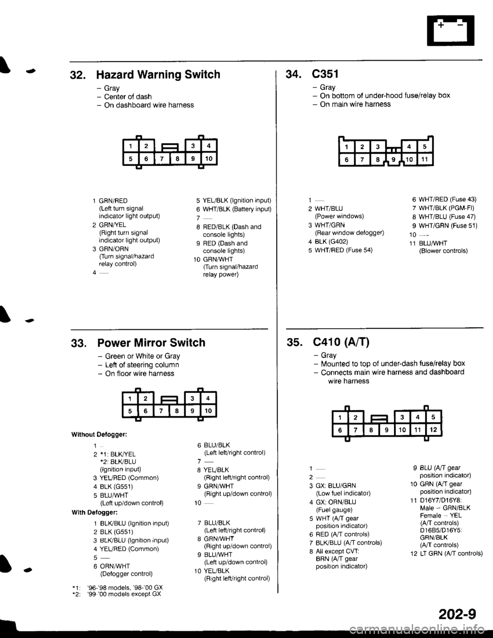
-32. Hazard Warning Switch
- Gray- Center ol dash- On dashboard wire harness
l GRN/RED(Left turn signalindicator light output)
2 GRN/YEL(Right turn signalindicator light output)
3 GRN/ORN
Ourn signal/hazardrelay control)
4
5 YEL/BLK (lgnition input)
6 WHT/BLK (Battery inpul)
7
8 RED/BLK (Dash andconsole lights)g RED (Dash andconsole lights)
1O GRNAVHT(Turn signal/hazardrelay power)
34. C351
- Gray- On bottom of under-hood fuse/relay box- On main wire harness
14
67I I9 I1011
2 WHT/BLU(Power windows)
3 WHT/GRN(Rear window defogger)
4 BLK (G402)
5 WHT/FED (Fuse 54)
6 WHT/RED (Fuse 43)
7 WHT/BLK (PGM-Fl)
8 WHT/BLU (Fuse 47)
I WHT/GRN (Fuse 51)
10 _
11 BLUAVHT(Blower controls)
33,
Without Oelogger:
1
2 *1: BLK,|YEL*2r BLKBLU(lgnition input)
3 YEURED (Common)
4 BLK (G551)
5 8LU,ryVHT(Left up/down control)
With Delogger:
1 BLIVBLU (lgnition input)
2 BLK (G551)
3 BLIVBLU (lgnition inPut)
4 YEURED (Common)
6 ORNMHT(Detogger control)
'96198 models, '98-'00 GX'99 00 models except GX
Power Mirror Switch
- Green or White or Gray- Left of steering column- On floor wire harness
6 BLU/BLK(Left left/right control)
8 YEUBLK(Right left/right control)
9 GRNAVHT(Right up/down control)
10
7 BLU/BLK(Lett left/right control)
8 GRNMHT(Right up/down control)
9 BLU/WHT(Lett up/down control)
1O YEL/BLK(Right left/right connol)
I
-
202-9
35. C41o (A/T)
- Gray- lilounted to top of underdash {use/relay box- Connects main wire harness and dashboard
wtre narness
2
3 GX: BLU/GRN
{Low fuel indicator)
4 GX: ORN/BLU(Fuelgauge)
5 WHT (A/T gearposition indicator)
6 RED (A,/T controls)
7 BLI(BLU (A,rT controls)
8 All except CVT:BRN (AiT gearposition indicator)
I BLU (Aft gearposition indicator)
10 GRN (A/I gearposition indicator)
11 D16Y7/D16Y8:Male - GRN/BLKFemale YEL(A/T conkols)D1685/D16Y5:GRN/BLK(M controls)
12 LT GRN (A/T controls)
Page 2121 of 2189
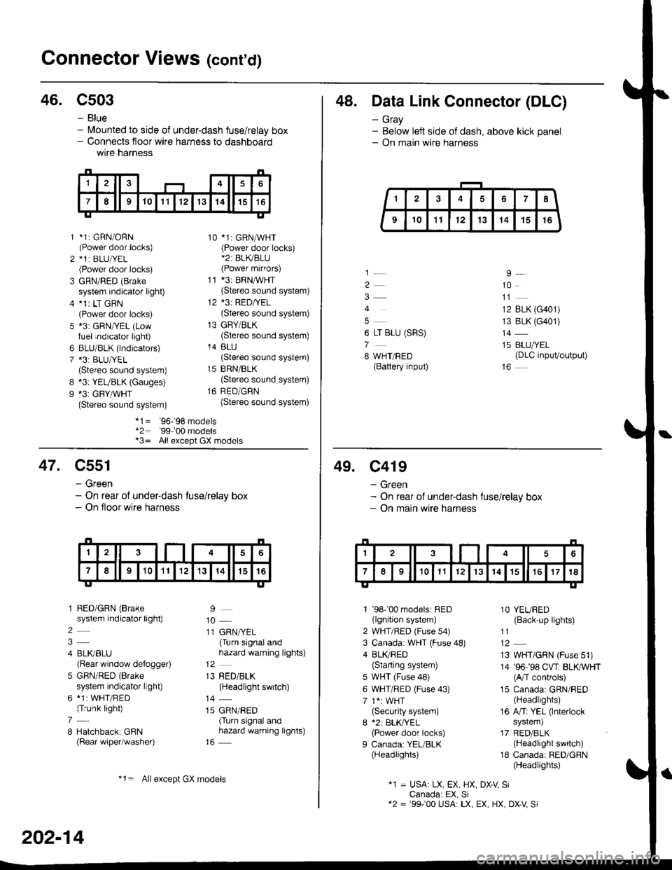
Gonnector Views (conrd)
46. C503
B
9
*1: GBN/ORN(Power door locks)*1r BLU|/EL(Power door locks)
GRN/RED (Brake
system indicator light)*1r LT GRN(Power door locks)*3: GRN/YEL (Lowfuel indicator light)
BLU/BLK (lndicators)*3: BLU/YEL(Stereo sound system)*3: YEUBLK (Gauges)*3: GRY/WHT(Stereo sound system)
10 *1: GRNAVHT(Power door locks)*2: BL(BLU(Power mirfors)
11 *3: BRNMHT(Stereo sound system)
12 *3: RED/YEL(Stereo sound system)
13 GRY/BLK(Stereo sound system)
14 BLU(Stereo sound system)
15 BRN/BLK(Stereo sound system)
16 RED/GBN(Stereo sound system)
- Blue- lvlounted to side of under-dash fuse/relay box- Connects floor wire harness to dashboardwtre narness
1
2
3
5
6
7
*1= '96-'98 models*2: '99-'00 models*3= All except GX models
48. Data Link Connector (DLC)
- Gray- Below left side of dash, above kick panel- On main wire harness
4
6 LT BLU (SRS)
7
8 WHT/BED(Battery input)
9
10
12 BLK (G401)
13 BLK (G401)
14
15 BLU/YEL(DLC inpuVoutput)
47. C551
- Green- On rear of under-dash tuse/relay box- On floor wire harness
1 BED/GRN (Brake
system indicator light)
2
4 BLI(BLU(Rear window defogger)
5 GBN/RED (Brake
system indicator llght)
6 *1: WHT/RED(Trunk light)
7
8 Hatchback: GBN(Rear wiper/washer)
9
10
11 GRN/YEL(Turn signal andhazard warning lights)
13 RED/BLK(Headlight switch)
14
15 GRN/RED(Turn signal andhazard warning lights)
202-14
*1= Allexcept GX models
49. C419
- Green- On rear of under-dash fuse/relay box- On main wire harness
1 '98''00 models: RED(lgnition system)
2 WHT/RED (Fuse s4)
3 Canada: WHT (Fuse 48)
4 BLI(RED(Starting system)
5 WHT (Fuse 48)
6 WHT/RED (Fuse 43)
7 1*: WHT(Security system)
I *2: BLK,TYEL
{Power door locks)
I Canada: YEL/BLK(Headlights)
1O YEURED(Back up lights)
11
13 WHT/GRN (Fuse 51)
14 '96-'98 CVT: BLKWHT(A/T controls)
15 Canada: GRN/RED(Headlights)
16 A/Ti YEL (lnterlock
system)
17 RED/BLK(Headlight switch)
18 Canada: RED/GRN(Headlights)
"1 = USA: LX, EX, HX, DX-V SiCanada: EX, Si12 = '99100 USA: LX, EX, HX, DX-V Si
Page 2123 of 2189
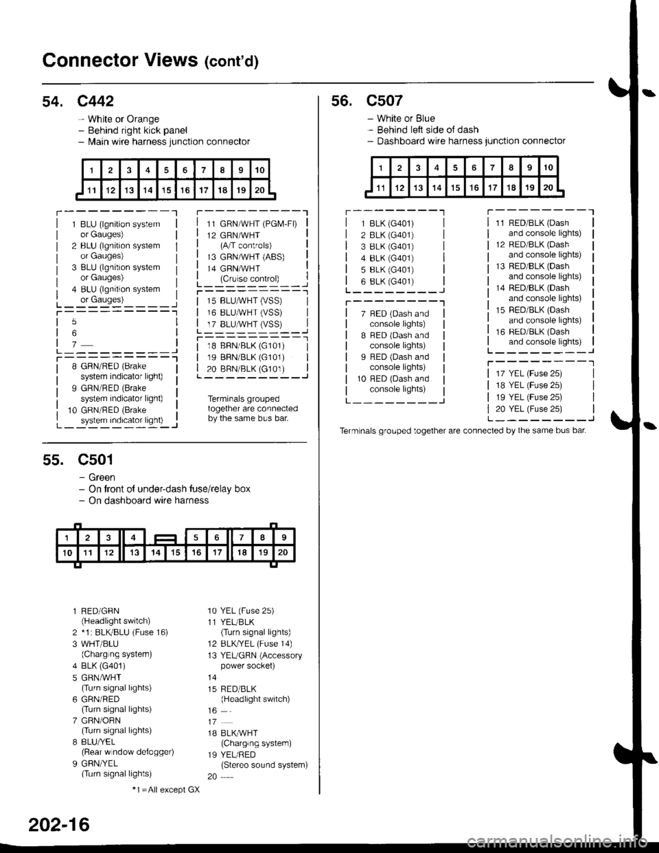
Connector Views (cont'd)
54. c442
- White or Orange- Behind right kick panel- l\,lain wire harness junction connector
r---------Tr---------"1
1 BLU (lgnition systemor Gauges)
2 BLU (lgnition syslemor Gauges)
3 BLU (lgnition systemor Gauges)
4 BLU (lgnition system
L_ or causes)L_-:-:::'-'�____Jt-----------1
11 GRN/WHT (PGM-FD
12 GRN/WHT(A/T controls)
13 GRNMHT (ABS)
14 GRNMHT
L_ lc,r'." .oIr"D_ _ _.jr----------_l
5
6
7L---------JT----------l8 GRN/RED (Brake
system indicator light)
9 GRN/RED (Brake
system indicator light)
10 GRN/RED (Brake
_ system indicator ligh0 -..1
| 15 BLUMHT (vSS) |I 16 BLUMHT (VSS) I
L T?_BLUSTrySS)--..]
l--------- - -l
| 18 BFN/BLK (G101) I| 19 BBN/BLK (G101) || 20 BRN/BLK (c101) |L---------J
Terminals groupedtogether are connectedby the same bus bar.
55. C501
- Green- On tront of under-dash tuse/relay box- On dashboard wire harness
l RED/GFN(Headlight switch)
2 *1 : BLKBLU (Fuse 16)
3 WHT/BLU(Charging systern)
4 BLK (G401)
5 GRNMHT(Turn signal lights)
6 GRN/RED(Turn signal lights)
7 GRN/ORN(Turn signal lights)
8 8LU/YEL(Rear w ndow delogger)
9 GFN/YEL(Turn signal lights)
'10 YEL (Fuse 25)
11 YEL/BLK(Turn signal lights)
12 BLKTYEL (Fuse 14)
13 YEUGRN (Accessorypower socket)
15 RED/BLK(Headlight switch)
1B BLK/WHT(Charglng system)
19 YEL/RED(Stereo sound system)
20
202-16
-1 =All e),cept GX
s6. c507
- White or Blue- Behind left side oJ dash- Dashboard wire harness junction connector
r --------'lT---------l
7 BED (Dash andconsole lights)
B BED (Dash andconsole lights)
I RED (Dash andconsole lights)
10 RFD (Dash andconsole lights)
11 RED/BLK (Dash
and console lights)
12 RED/8LK (Dash
and console lights)
13 RED/BLK {Dashand console lights)
14 RED/BLK (Dash
and console lights)
15 RED/BLK (Dash
and console lights)
16 RED/BLK (Dash
and console lights)L--------J
T--------T
L---_---_J
1 BLK (G401)
2 BLK (G401)
3 8LK {G401)4 8LK (G401)
5 BLK (G401)
6 8LK (G401)L________J
T--------"1
17 YEL (Fuse 25)
18 YEL (Fuse 25)
19 YEL (Fuse 25)
20 YEL (Fuse 25)L--------J
Term nals grouped together are connected by the same bus bat
Page 2127 of 2189
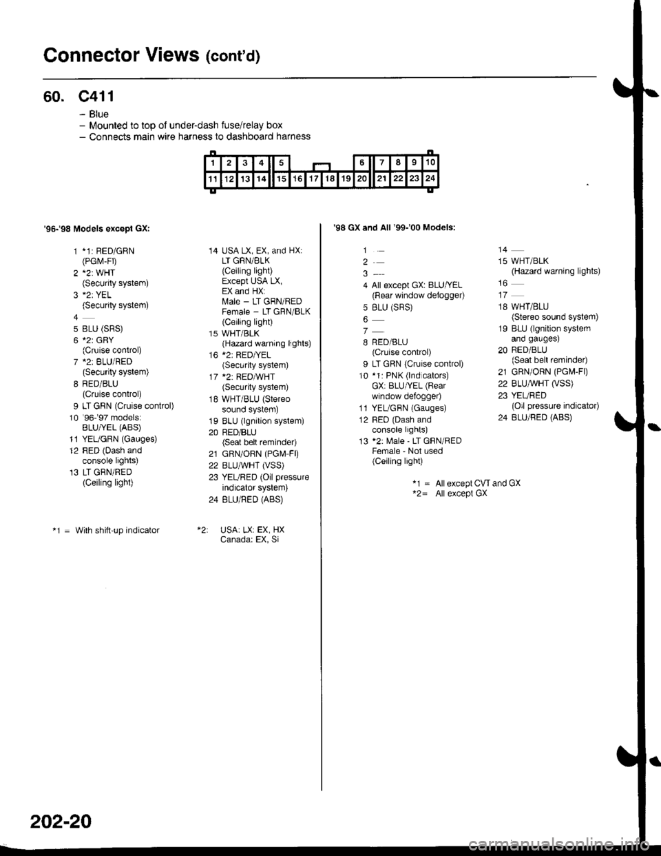
Connector Views (cont'd)
60. c411
- Blue- Mounted to top ol under-dash fuse/relay box- Connects main wire harness to dashboard harness
'95198 Models excepl GXI
1 *1: RED/GRN(PGrvr-FD
2 A2: WHT(Security system)
(Security system)
4
5 BLU (SRS)
6 *2r GRY(Cruise control)
7 *2: BLU/RED(Security system)
8 RED/BLU(Cruise control)
9 LT GRN (Cruise control)
10 '96-�97 models:BLU/YEL (ABS)
11 YEUGRN (Gauges)
12 RED (Dash andconsole lights)'13 LT GRN/RED(Ceiling light)
*1 = With shitt-up indicator
14 USA LX, EX, and HX:LT GRN/BLK
{Ceiling light)Except USA LX,EX and HX:ftrale - LT GRN/REDFemale - LT GRN/BLK(Ceiling light)
15 WHT/BLK(Hazard warning lights)
16 *2: RED|YEL(Security system)
17 *2: REDA/VHT(Security system)
18 WHT/BLU (Stereo
sound system)
19 BLU (lgnition system)
20 RED/BLU(Seat bett reminder)
21 GRN/OBN (PGN4 FD
22 BLUAVHT (VSS)
23 YEURED (Oil pressure
indicator system)
24 BLU/RED (ABS)
USA: LX: EX, HXCanadar EX, Si
202-20
'98 GX and All '99-'00 Models:
1
2
4 All except GX: BLU/YEL(Rear window defogger)
5 BLU (SRS)
7
B RED/BLU(Cruise control)
9 LT GRN {Cruise control)
10 *1: PNK (lnd cators)GX: BLU/YEL (Bear
window defo9ger)
1l YEL/GBN (Gauges)
12 RED (Dash andconsole lights)
13 *2: Male - LT GRN/REDFemale - Not used(Ceiling light)
14
15 WHT/BLK(Hazard warning lights)
18 WHT/BLU(Stereo sound system)
19 BLU (lgnition systemano gaugesl
20 RED/BLU(Seat bell reminder)
21 GRN/ORN (PG[,4-Fl)
22 BLU,ryVHT O/SS)23 YEURED(Oil pressure indicator)
24 BLU/RED (ABS)
*1 = Allexcept CW and GX*2= All except GX
Page 2131 of 2189
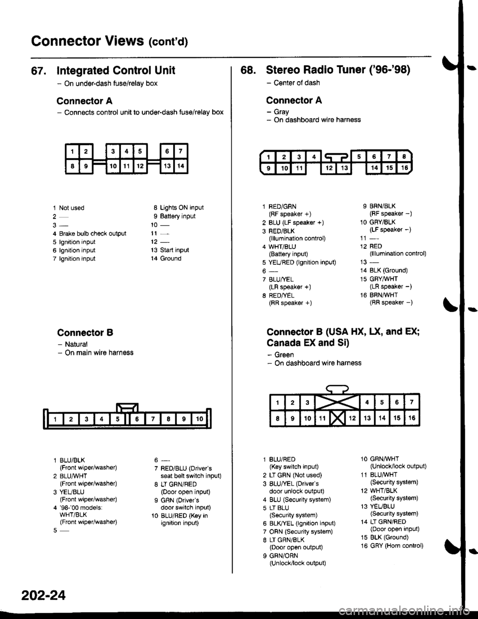
Gonnector Views (cont'd)
67. Integrated Control Unit
- On underdash fuse/relay box
Connector A
- Connects control unit to under-dash fuse/relay box
1 Not used
4 Erake bulb check output
5 lgnition input
6 lgnition input
7 lgnjtion input
Connectol B
- Natural- On main wire harness
l BLU/BLK
{Front wiper/washer)
2 BLUA/VHT(Front wiper/washe0
3 YEUBLU(Front wiper/washer)
4 '98-'00 models:WHT/BLK(Front wiper/washer)
8 Lights ON input
9 Battery input
11 _
13 Start input
14 Ground
7 RED/BLU (Driver's
seat b€lt switch input)
8 LT GRN/RED(Door open input)
I GRN (Oriver's
door switch input)'t0 BLU/RED (Key inignition input)
202-24
68. Stereo Radio Tuner ('96-'98)
- Center ot dash
Connector A
- Gray- On dashboard wire harness
1 RED/GRN(RF speaker +)
2 BLU (LF speaker +)
3 RED/BLK(lllumination control)
4 WHT/BLU(Battery input)
5 YEURED (lgnition input)
6-
7 BLU/YEL(LR speaker +)
8 RED/TEL(RR speaker +)
9 BRN/BLK(RF speaker -)
1O GRY/BLK(LF speaker -)
12 RED(lllumination control)
14 BLK (Ground)
15 GFY,4/VHT(LR speaker -)
16 BRNAVHT(RR speaker -)
Connector B (USA HX, UX, and EX;
Canada EX and Si)
- Green- On dashboard wire harness
l BLU/RED(Key switch input)
2 LT GRN (Not used)
3 BLU/'EL (Drivels
door unlock output)
4 BLU (Security system)
5 LT BLU
{Security system)
6 BLIVYEL (lgnition input)
7 ORN (Security system)
8 LT GRN/BLK(Door open output)
9 GRN/ORN(Unlock/lock output)
1O GRNAVHT(Unlock/lock output)
1 1 BLU/WHT(Security system)
'2 WHT/BLK(Security system)
13 YEUBLU(Security system)
14 LT GRN/RED(Door open input)
15 BLK (Ground)
16 GRY (Horn conkol)
Page 2137 of 2189
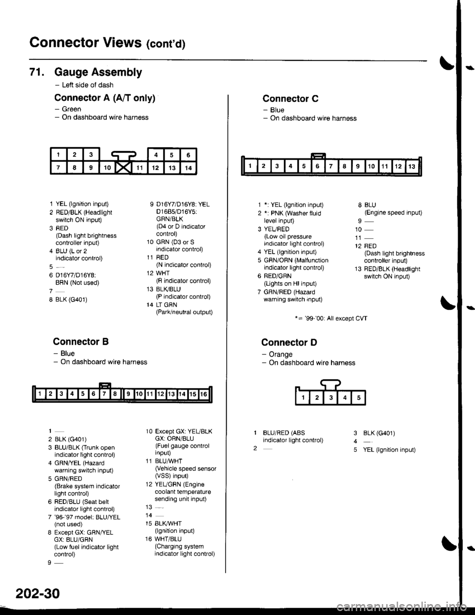
Connector Views (conrd)
71. Gauge Assembly
- Left side of dash
Connector A (A/T only)
- Green- On dashboard wire harness
1 YEL (lgnition input)
2 RED/BLK (Headlight
switch ON input)
3 RED(Dash light brightnesscontroller input)
4 BLU (L or 2indicator control)
6 D16Y7/D16Y8:BRN (Not used)
8 BLK (G401)
Connector B
- Blue- On dashboard wire harness
2 BLK (G401)
3 BLU/BLK (Trunk openindicator light control)
4 GRN/YEL (Hazard
warning switch input)
5 GRN/RED(Brake system indicatorlight control)
6 RED/BLU (Seat beltindicator light control)
7 '96-'97 model: BLU,ryEL(not used)
8 Except GX: GRN/YELGX: 8LU/GRN(Low fuel indicator lightcontrol)
9 D16Y7/D16Y8: YEL01685/016Y5:GRN/BLK(D4 or D indicatorcontrol)
10 GRN (03 or Sindicator control)
11 RED(N indicator control)
12 WHT(F indicator control)
13 BLI(BLU(P indicator control)
14 LT GBN(Park/neutral output)
10 Except GX: YEUBLKcX: ORN/BLU(Fuel gauge controlinput)
11 BLUAVHT(Vehicle speed sensor(VSS) input)
12 YEUGRN (Engine
coolant temperaturesending unit input)
14
15 BLI(IVHT(lgnition input)
16 WHT/BLU(Charging systemindicator light control)
202-30
Connector C
- Blue- On dashboard wire harness
1 *: YEL (lgnition input)
2 *: PNK (Washer lluidlevel input)
3 YEUBED(Low oil pressureindicator light control)
4 YEL (lgnition input)
5 GRN/ORN (Malfunctionindicator light control)
6 RED/GRN
{Lights on Hl input)
7 GBN/RED (Hazardwarning switch input)
*= '99-'00: All except CVT
Connector D
- Orange- On dashboard wire harness
BLU/RED (ABS
indicator light control)
8 BLU(Engine speed input)
10
12 FED(Dash light brightnesscontroller input)
13 RED/BLK (Headlightswitch ON input)
I
2
3
4
5
BLK (G401)
YEL (lgnition input)
Page 2138 of 2189
\
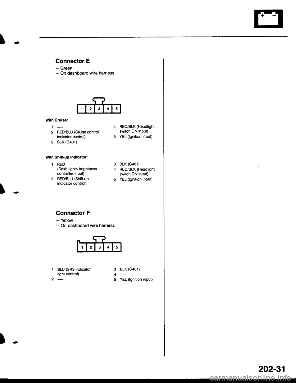
Connector E
- Groen- On dashboard wire harness
T
Wllh Crulss:
1-
2 RED/BLU (Cruise conkolindicator control)
3 BLK (G401)
Wlth Shtft-up Indlcator:
1 RED(Dash lights brightn€ss
controller inPut)
2 RED/BLU (Shift-up
indicator control)
4 RED/BLK (Headlight
switch ON input)
5 YEL (lgnition input)
BLK (G401)
RED/BLK (Headlight
switch ON input)
YEL (lgnition input)
BLK (G401)
YEL (lgnition input)
3
5
1
2
Connector F
- Yellow- On dashboard wir€ harness
BLU (SRS indicatorlight control)
)-
202-31