Control arm HONDA CIVIC 1998 6.G Repair Manual
[x] Cancel search | Manufacturer: HONDA, Model Year: 1998, Model line: CIVIC, Model: HONDA CIVIC 1998 6.GPages: 2189, PDF Size: 69.39 MB
Page 2064 of 2189
Security System (cont'd)
3.
Security System Does Not Disarm With
The Valet Switch
Security System Does Not Work In The
Valet Mode ('99-'00 models)
1. ls fuse 3 (in the under-dash fuse box) (HX, LX,
EX, DX-V, Si) or the fuse in the securily in-line
luse holder (CX, DX) OK?
Yes - Go to the next step.
No - Replace the blown fuse, then go to the
next step.
Does the fuse blow again?
Yes - Locate and reoair the short.
No- Retest the system.
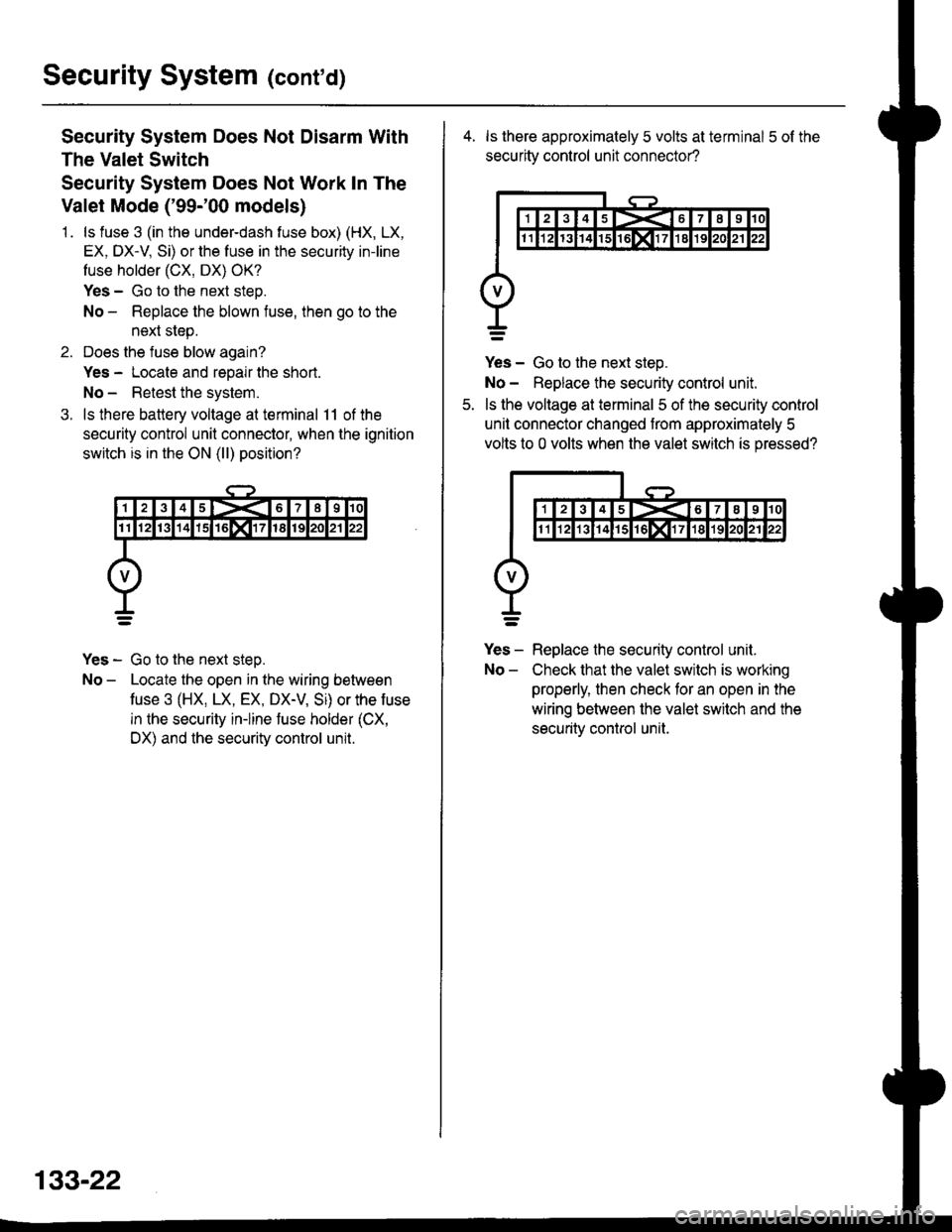
ls there battery voltage al terminal 11 of the
security control unit connector, when the ignition
switch is in the ON (ll) position?
Yes - Go to the next steo.
No - Locate the open in the wiring between
fuse 3 (HX, LX, EX, DX-V, Si) or the luse
in the security inline fuse holder (CX,
DX) and the securiv control unit.
133-22
4. ls there approximately 5 volts at terminal 5 of the
security control unit connector?
Yes - Go to the next steo.
No - Replace the security control unit.
ls the voltage at terminal 5 of the security control
unil connector changed from approximately 5
volts to 0 volts when the valet switch is pressed?
Yes - Replace the security control unit.
No - Check that the valet switch is working
properly, then check for an open in the
wiring between the valet switch and the
security control unit.
Page 2065 of 2189
Security System Alarm Does Not Trigger
When The System ls Armed And The
Trunk Or A Door ls Opened
Security System Does Not "Be€p" 3 Times
When The System is Armed With The Trunk
Or A Door Open (HX, LX, EX, Dx-V SD
1. Place the ceiling light in the center position, then
open and close the doors one at a time. Do all
the doors operate the ceiling light properly?
Yes - Go to the next steo.
No - Repair the ceiling light circuit.
With the ignition switch in the ON (ll) position,
does the trunk open indicator in the gauge
assembly come on with the trunk open?
Yes - Go to the next step.
No - Faulty trunk latch switch or an open in the
BLU/BLK wire.
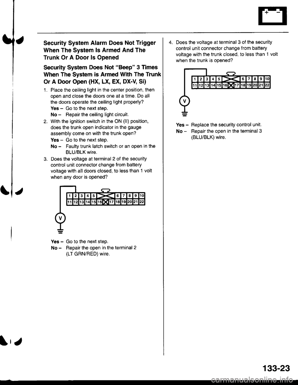
Does the voltage at terminal 2 of the security
control unit connector change trom battery
voltage with all doors closed, to less than I volt
when any door is opened?
Yes - Go to the next step.
No - Repair the open in the terminal 2
(LT GRN/RED) wire.
4. Does the voltage at terminal 3 of the security
control unit connector change from battery
voltage with the trunk closed, to less than 1 volt
when the trunk is opened?
Yes - Replace the security control unit.
No - ReDair the oDen in the terminal 3
(BLU/BLK) wire.
133-23
Page 2066 of 2189
Security System (conrd)
Parking Lights Do Not Flash (CX, DX)
1 . Do the parking lights, headlights, and taillights
come on with the headlight switch in the HEAD
position?
Yes - Go to the next step.
No - Repair the parking lights, headlights, or
taillights circuit.
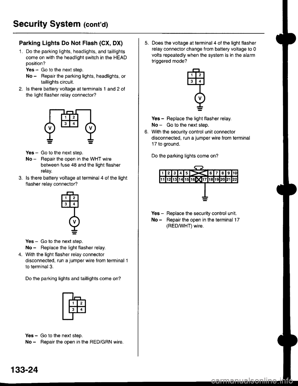
2. ls there battery voltage at terminals 1 and 2 of
the light flasher relay connector?
dHl
.t.
Yes - Go to the next step.
No - Repair the open in the WHT wire
between fuse 48 and the light flasher
relay.
ls there battery voltage at terminal 4 of the light
flasher relay connector?
-F-,
tlllJt3l4l
Intvl
r=
Yes - Go to the next step.
No - Replace the light flasher relay.
With the light flasher relay connector
disconnected, run a jumper wire from terminal 1
to terminal 3.
Do the parking lights and taillights come on?
Yes - Go to the next step.
No - Repair the open in the RED/GRN wire.
133-24
5. Does the voltage at terminal 4 of the light flasher
relay connector change from battery voltage to 0
volts repeatedly when the system is in the alarm
triggered mode?
Yes - Replace the light flasher relay.
No - Go to the next step.
With the security control unit connector
disconnected, run a jumper wire from termrnal
17 to ground.
Do the parking lights come on?
Yes - Replace the security control unit.
No - Repair the open in the terminal 17
(REDAIVHT) wire.
q
I=
Page 2069 of 2189
Starter Cut Does Not Work Properly
(HX, LX, EX, DX-V, Si)
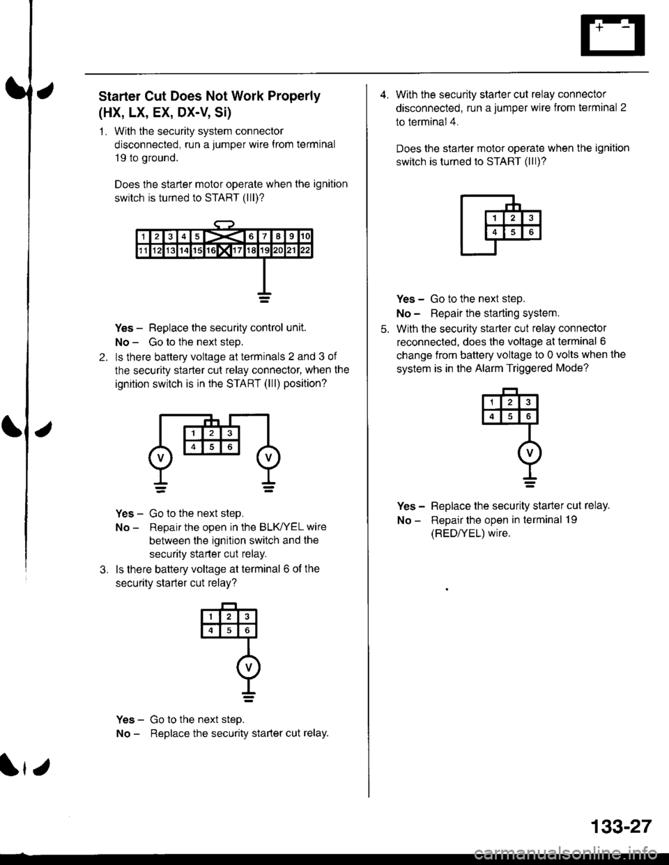
1 . With the security system connector
disconnected, run a jumper wire f rom terminal
19 to ground.
Does the starter motor operate when the ignition
switch is turned to START (lll)?
2.
Yes - Replace the security control unit.
No - Go to the next steD.
ls there baltery voltage at terminals 2 and 3 of
the security starter cut relay connector, when the
ignition switch is in the START (lll) position?
Yes - Go to the next step,
No - Reoair the ooen in the BLK/YEL wire
between the ignition switch and the
security starter cut relay.
ls there battery voltage at terminal 6 of the
securitv starter cut relav?
Yes - Go to the next steo.
No - Replace the security starter cut relay.
3.
@
I=
r
133-27
4. With the security starter cut relay connector
disconnected, run a jumper wire from terminal 2
to terminal 4.
Does the slarter motor operate when the ignition
switch is turned to START (lll)?
5.
Yes - Go to the next step,
No - Repair the starting system.
With the security starter cut relay connector
reconnected, does the voltage at terminal 6
change from battery voltage to 0 volts when the
system is in the Alarm Triggered Mode?
Yes - Replace the security starter cut relay.
No - Repair the open in terminal 19
(BED/YEL) wire.
4
I=
Page 2070 of 2189
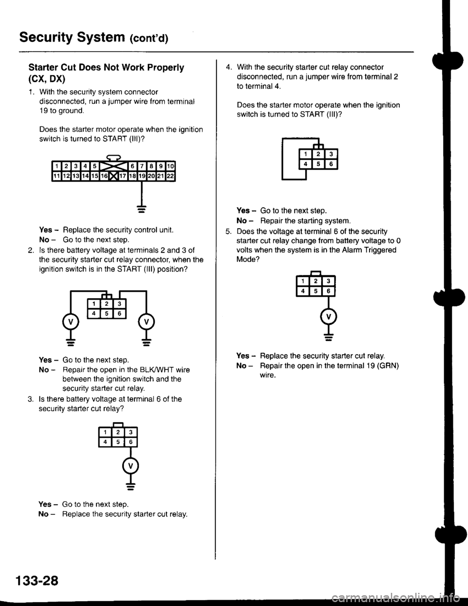
Security System (cont'd)
Starter Cut Does Not Work Properly
(cx, Dx)
1 . With the security system connector
disconnected, run a jumper wire f rom terminal
19 to ground,
Does the starter motor operate when the ignition
switch is turned to START (lll)?
Yes - Replace the security control unit.
No - Go to the next steo.
ls there battery voltage at terminals 2 and 3 of
the security starter cut relay connector, when the
ignition switch is in the START (lll) position?
Yes - Go to the next step.
No - Repair the open in the BLKMHT wire
between the ignition switch and the
security starter cut relay.
ls there battery voltage at terminal 6 of the
securitv starter cut relav?
Yes - Go to the next step.
No - Beplace the security starter cut relay.
4
o
t_=
133-28
4. With the security starter cut relay connector
disconnected, run a jumper wire from terminal 2
to terminal 4.
Does the starter motor operate when the ignition
switch is turned to START (lll)?
Yes - Go to the next steo.
No - Repair lhe starting system.
Does the voltage at terminal 6 of the security
starter cut relay change trom battery voltage to 0
volts when the system is in the Alarm Triggered
Mode?
Yes - Replace the security starter cut relay.
No - Repair the open in the terminal 19 (GRN)
wtre.
q
I=
Page 2071 of 2189
.1,
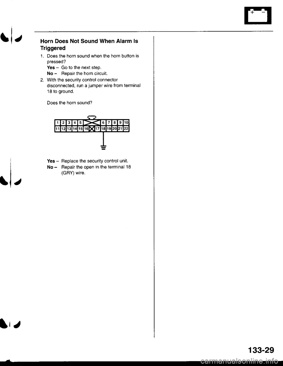
Horn Does Not Sound When Alarm ls
Triggered
1. Does the horn sound when the horn button is
pressed?
Yes - Go to the next step.
No- Repair the horn circuit.
2. With the security control connector
disconnected, run a jumper wire f rom terminal'18 to ground.
Does the horn sound?
Yes - Replace the security control unit.
No - Repair the open in the lerminal 18
(GRY) wire.
lr I
133-29
Page 2117 of 2189
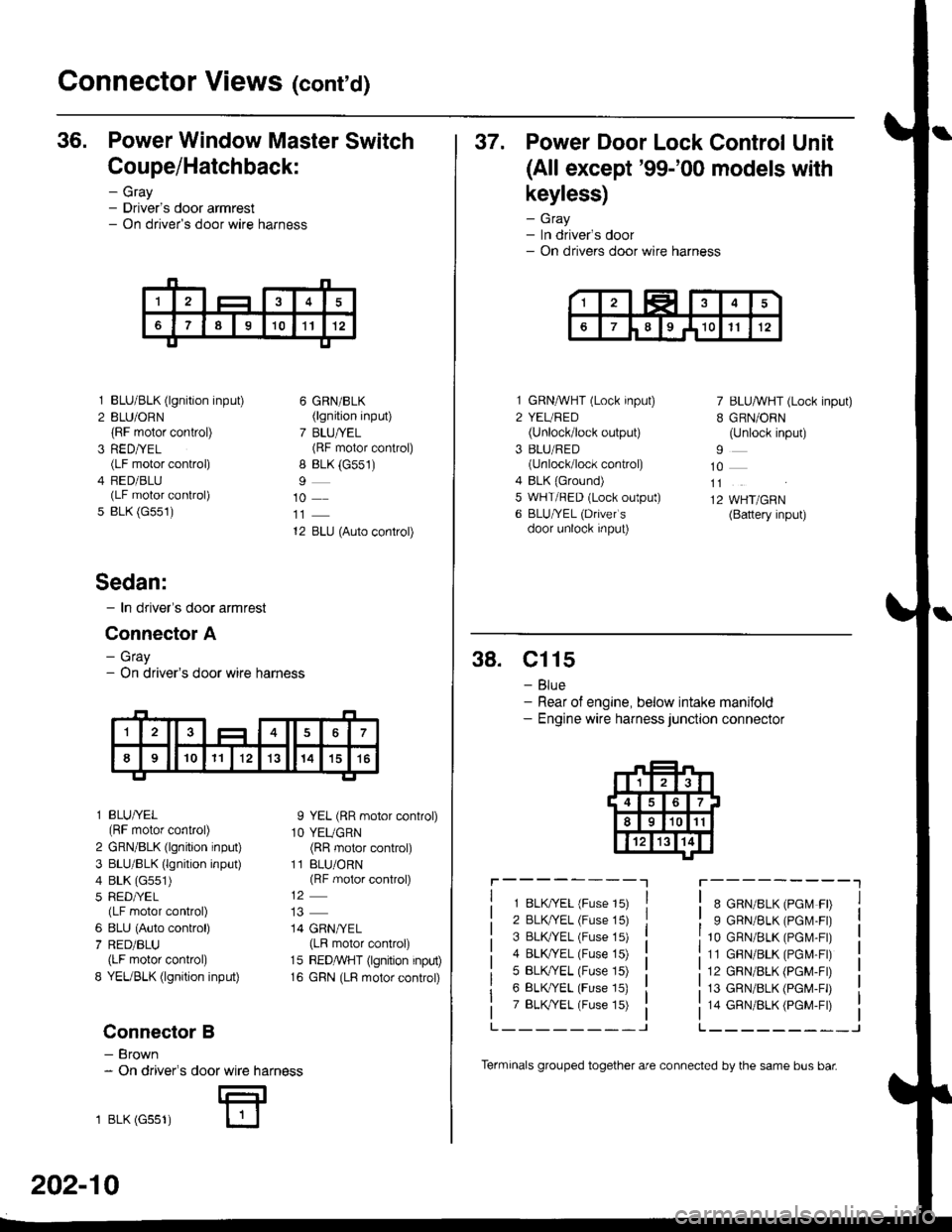
Connector Views (cont'd)
36. Power Window Master Switch
Coupe/Hatchback:
- Gray- Driver's door armrest- On driver's door wire harness
3
5
BLU/BLK (lgnition input)
BLU/ORN(RF motor control)
RED/YEL(LF motor control)
FED/BLU(LF motor control)
BLK (G551)
6 GRN/BLK(lgnition input)
7 BLU/YEL(RF motor control)
8 BLK (G551)
10
12 BLU (Auto control)
I YEL (RR motor control)
1O YEUGRN(RR motor control)
11 BLU/ORN(RF motor control)
14 GRN/YEL(LR motor control)
15 REDMHT (lgnition input)
16 GRN (LR motor control)
Sedan:
- In driver's door armrest
Connector A
- Gray- On driver's door wire harness
l BLU/YEL(RF motor control)
2 GRN/BLK (lgnition input)
3 BLU/BLK (lgnition input)
4 BLK (G551)
5 RED/YEL(LF motor control)
6 8LU (Auto control)
7 RED/BLU(LF motor control)
8 YEUBLK (lgnition input)
Connector B
- Brown- On driver's
1 BLK (Gss1)
door wire harness
E
202-10
Terminals grouped together are connected by the same bus bar
37. Power Door Lock Control Unit
(All except'99-'00 models with
keyless)
- Gray- In driver's door- On drivers door wire harness
1 GRNMHT (Lock input)
2 YEURED(Unlock/lock output)
3 BLU/RED(unlock/lock control)
4 BLK {Ground)5 WHT/RED (Lock output)
6 BLU/YEL (Drivefs
door unlock input)
7 BLU/WHT (Lock input)
B GRN/ORN(Unlock input)
10
11
12 WHT/GRN(Battery input)
38. Cl15
- Blue- Rear of engine, below intake manifold- Engine wire harness junction connector
r----------lr---------"1
1 8LK?ryEL (Fuse 15)
2 BLK/YEL (Fuse 15)
3 BLK TEL (Fuse 15)
4 BLK/YEL (Fuse 15)
5 BLK,/YEL (Fuse 15)
6 BLK/YEL (Fuse 15)
7 BLK,TYEL (Fuse 15)
8 GRN/8LK (PGM FD
9 GRN/BLK (PGM.FD
10 GRN/BLK (PGr\,4-Fr)
11 GBN/BLK (PGM-Fr)
12 GRN/BLK (PGM-FD
13 GRN/BLK (PGM-FD
14 GRN/BLK (PGM-Fr)
L_______-JL______--_J
Page 2124 of 2189
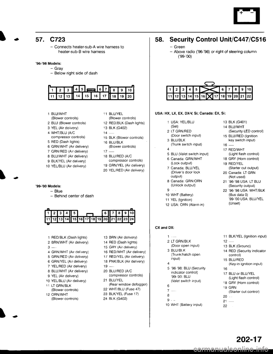
-57. c723
- Connects heater-sub-A wire harness to
heater-sub-B wire harness
'96-'98 Models:- Gray- Below right side of dash
l BLUAVHT(Blower controls)
2 BLU (Blower controls)
3 YEL (Air delivery)
4 WHT/BLU (A/Ccompressor controls)
5 RED (Dash lights)
6 GRN^VHT (Air delivery)
7 GRN/RED (A r delivery)
I BLUAVHT (Air delivery)
9 BLK,ryEL (Air delivery)
10 YEUBLU (Air delivery)
11 BLU/YEL(Blower controls)
12 BED/BLK (Dash lights)
13 BLK (G402)
t4
15 BLK (Blower conlrols)
16 BLU/BLK(Blower controls)
18 BLU/RED (A/C
compressor controls)
19 GRN/YEL (Air delivery)
20 YEURED (Air delivery)
'99-'00 Models:- Blue- Behind center ot dash
1 RED/BLK (Dash lights)
2 BRNMHT (Au delivery)
4 GRNA/VHT (Air delvery)
5 GBN/BED (Air delivery)
6 GRN/YEL (Alr delivery)
7 YEURED (Air delivery)
8 BLU,ryVHT (Au delivery)
9 YEL (An delivery)
10 YEUBLU (Arr delivery)
11 LT GRN/BLK(Blower controls)
12 ORN,AiVHT(Blower controls)
13 BBN (Air delivery)
14 RED (Dash lights)
15 GRY (Air delrvery)
16 RED,ryVHT (Air delivery)
17 RED/YEL (Air delivery)
18 PNK/BLK (Air delivery)
19
20 BLU/RED (A/C
compressor controls)
21 BLUI/EL(Bear window defogger)
22 WHT/BLU (Fuse 47)
23 BLKryEL (Fuse 17)
24 BLK \G402)
I
1415617I910
1l1213141617181920
58. Security Control UnitiC447lC516
- Green- Above radio ('96-�98) or right of steering column
(99-'�00)
USA: HX, LX, EX, DX-V Si; Canada: EX, Si:
1 USA: YEUBLU(Set)
2 LT GRN/RED(Door swiich input)
3 BLU/BLK(Trunk switch rnput)
4
5 BLU (valet switch inpu0
6 Canadai GFNAVHT(Lock output)
7 Canada: BLU/YEL(Driver's door lockoulpurJ
I Canada: GRN/OBN(Unlock output)
9
10 WHT (Battery)
11 YEL (lgnition)
12 USA: OHN (Alarm in)
CX and DX:
1
2 LT GRN/BLK(Door open input)
3 BLU/BLK(Trunk/hatch openinput)
5 '96 '98: BLU (Security
ndicator control)99- 00: BLU(Valel switch input)
6
7
B
I
10 WHT (Battery input)
13 BLK (G401)
14 BLUMHT(Security LED conkol)
15 BLU/RED (lgnitionkey switch input)
17 REDAVHI(Light flash control)
18 GRY (Horn conkol)
19 RED/YEL(Starter cut output)
20 Canada: LT GRN(Nol used)
21 ,96-,98 USA: LT BLU(Security output)
22 '96 98 USA: WHT/BLK(Bus data 0)'99-'00 USA: BLU/YEL(Unset)
11 BLK/YEL (lgnition input)
13 BLK (Ground)
14 RED (Security indicatorcontrol)
15 BLU/RED(Key in ignition input)
16
17 BLU or BLU/YEL(Light tlash control)
18 GRY (Horn control)
19 GRN(Slarter cut control)
20
22
1><678910
1112131415rGlxllT1819202122
202-17