Battery HONDA CIVIC 1998 6.G Repair Manual
[x] Cancel search | Manufacturer: HONDA, Model Year: 1998, Model line: CIVIC, Model: HONDA CIVIC 1998 6.GPages: 2189, PDF Size: 69.39 MB
Page 739 of 2189
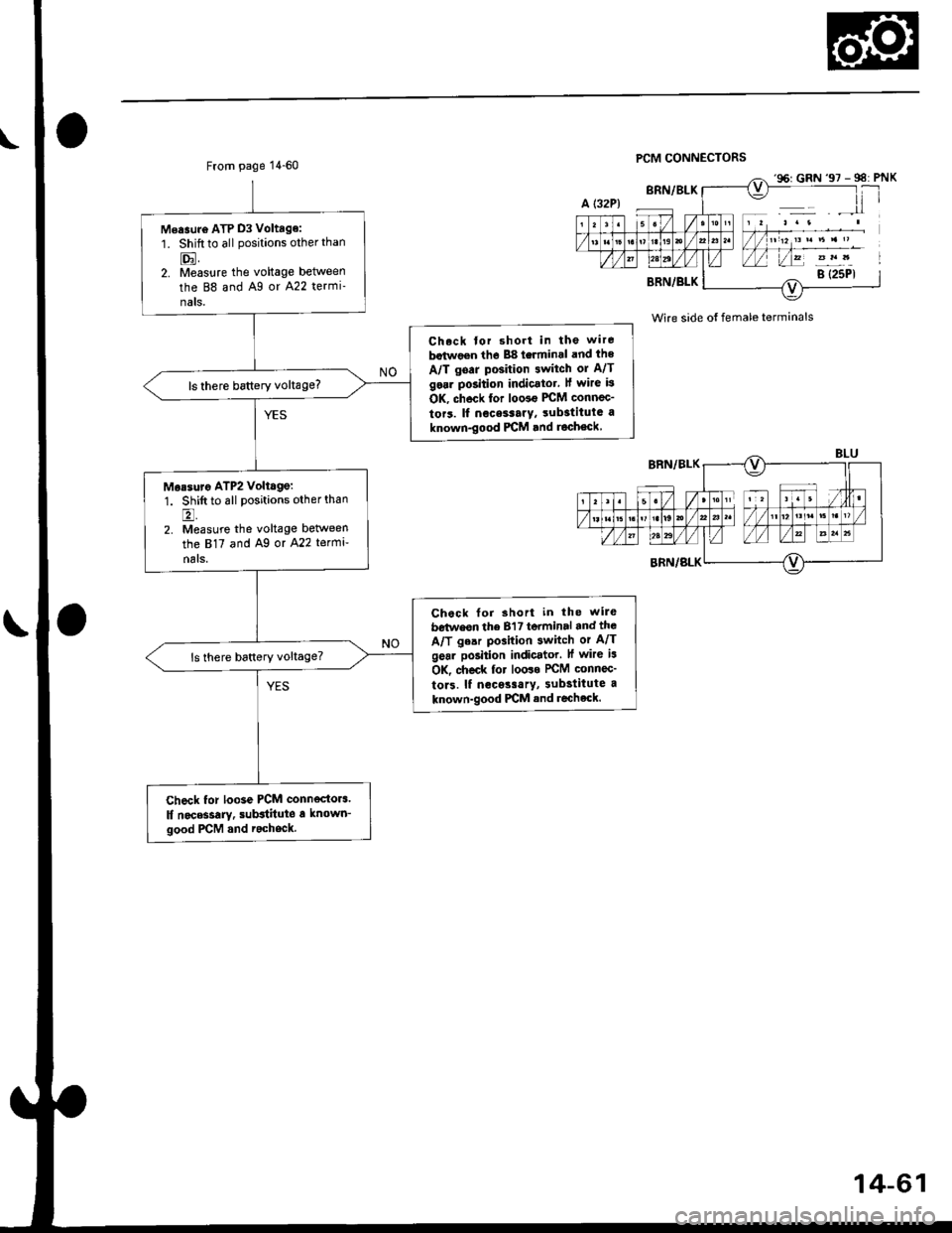
From page 1 4-60PCM CONNECTORS
Wire side ot female terminals
Measuro ATP D3 Voltage:
1. Shift to all positions other than
tr.2. Measure the voltage between
the 88 and A9 or A22 termi-
nals.
Ch.ck tor short in the wire
botwoen tho 88 terminal and ihe
A/T goar position 3witch ol A/T
gosr position indicator, ll wirc is
OK, chock for loo3€ PCM connec-
tor3. lf nece3rary, substituta a
known-good PCM lnd roch€ck
ls there battery voltage?
Morsuro ATP2 Voltage:
1. Shift to all positions other than6t
2. Measurc the voltage between
the 817 and Ag or A22 terml-
n6ls.
Check for short in the wile
b€twesn the B'l 7 terminal and the
A/T ge.r pGition switch or A/T
gear po3ition indicator. lf wire i3
OK, check for loo3o rcM connec'
to13. lf necossarY, substitute a
known-good PICM and recheck.
ls there battery voltage?
check for loose PCM connectors.
lf noc*sarY. sub3titute a known_
good PCM and r.chock.
'96: GRN'97 - 98: PNX
B (25P1
14-61
Page 757 of 2189
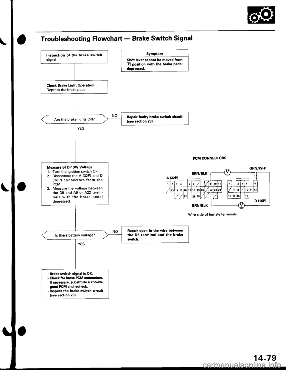
Troubleshooting Flowchart - Brake Switch Signal
Symptom
Shift lever cannol b€ moved f.om
B pGition with the brako podrl
depr8sed.
PCM CONNECTORS
Check Brako Light Operation:Deoress the brake pedal.
Rop.ir faulty braks switch cilcuit
lsos soction 231.Are the brake lights ON?
Measure SToP SW Vohag€:1. Turn the ignition switch OFF.2. Disconnect the A l32P) and D
{l6P) connectors from thoPCM.3. Measure the voltage belweenthe D5 and A9 or A22 termi-nals with the brake Pedaldepressod.
Rap.i. opon in the wira bctn oentha 05 terminal and tho btrkclwitdr.ls there battery voltage?
. Brake switch 3ign.l is OK.. Ch6ck lor looao PCM oonnoctors.It nocassary, aubctilute a known-good PCM and r€check.. Inspoct the brake switch circuit
{s6e section 231.
Wire side of lemale terminals
Page 760 of 2189
Electrical Troubleshooting ('99 - 00 Models)
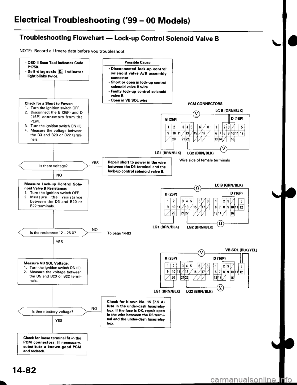
Troubleshooting Flowchart - Lock-up Control Solenoid Valve B
NOTE| Record allfreeze data before you troubleshoot.
Possibla Cause
. Oisconnected lock-uD controlsolenoid velve A/B assemblyconnector. Short or open in lock-up controlsolenoid valv€ B wire. Faulty lock-up control solenoidvalve B' Open in VB SOL wirercM CONNECTORS
To page 14-83
' OBD ll Scan Tool indic.tes CodeP1758.. Self-diagnosis E indicatorlight blinks twice.
Chack for a Short to Power:1. Turn the ignition switch OFF.2. Disconnect the I (25P) and D(16P) connectors from thePCM.3. lurn the ignition switch ON (ll).4. Measure the voltage betweenthe D3 and 820 ot 822 tetmi-nals,
Repair short to power in the wirebetween the D3 terminal and thelock-up contlol solenoid valve B.
Measure Lock-up Control Sole-noid Vdlve I R8i3tance:1. Turn the ignition switch OFF.2, Measure the resistancebetween the D3 and 820 or822 terminals.
ls the resistance 12 - 25 O?
Measure VB SOL Voltago:1. Turn the ignition switch ON lll).2. Measure the voltage betweenthe D5 and 820 or 822 termi-nals.
Check for blown No. 15 {7.5 Alfus€ in the under-dash luse/releybox. It the fuse is OK, repair openin the wir6 between th6 DS terminal and the under-dash fuse/rebyoox,
ls there battery voltage?
Chock for loose te.minal fit in thePCM connectors. It necessary,substitute a known-good PCMend recheck.
B t2sP) ll D t15P)
Wire side ol female terminals
I {2sPt ll D (16Pt
B (25P1 D t16Pt
\
14-82
Page 762 of 2189
Electrical Troubleshooting ('gg - 00 Models)
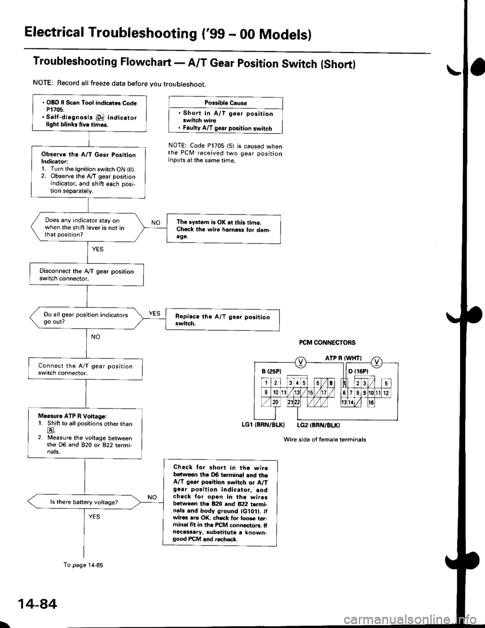
Troubleshooting Flowchart - A/T Gear position Switch (Short)
NOTE: Record all freeze data before you troubleshoot.
Po$ible Cause
' Short in A/T go.r positionswhch wire. Faulty A/T goar position switch
NOTE: Code P1705 (5)the PCM received twoinputs at the same time.
is caused whengear position
PCM CONNECTORS
LGl (BRN/BLK) LG2 (BRN/BLKI
Wire side of femaleterminals
B {25P1 llD (16P1
. OBD ll Scan Tool indicrtB CodeP1?05.. Solt-diagno3i3 E indicatorlight blink. tive times.
Observo the A/T Gear PositionIndicetori1. Turn the ignition switch ON fit).2. Observe the lVT gear positionindicator, and shift each posi,!on separately.
Does any indicator stay onwhen the shift lever is not inthat position?
The sFtom is OK at thi3 time.Check the wi.e harness for dam-aga.
Do all gear position indicatorsgo out?
Moasure ATP R Voltage:1. Shift to all positions otherthanE.2. Measure the voltage betweenthe DG and 82O o( 822 terfii-nats.
Check tor short in the wirebatwoen tha DB terminal and theA/T go.r porhion switch or A/Tg6ar po3ition indicator, andchock for opon in the wiresbetween the B20 and B22 t€rmi-n.ls and body ground (G10 . tfwir€c rro OK, chsck fo. loo3e tel-ftinal fit in the FCM connectors. llnoceisary, substiiute e known-good FCM and r€check.
ls there battery voltage?
To page 14-85
\
14-84
Page 763 of 2189
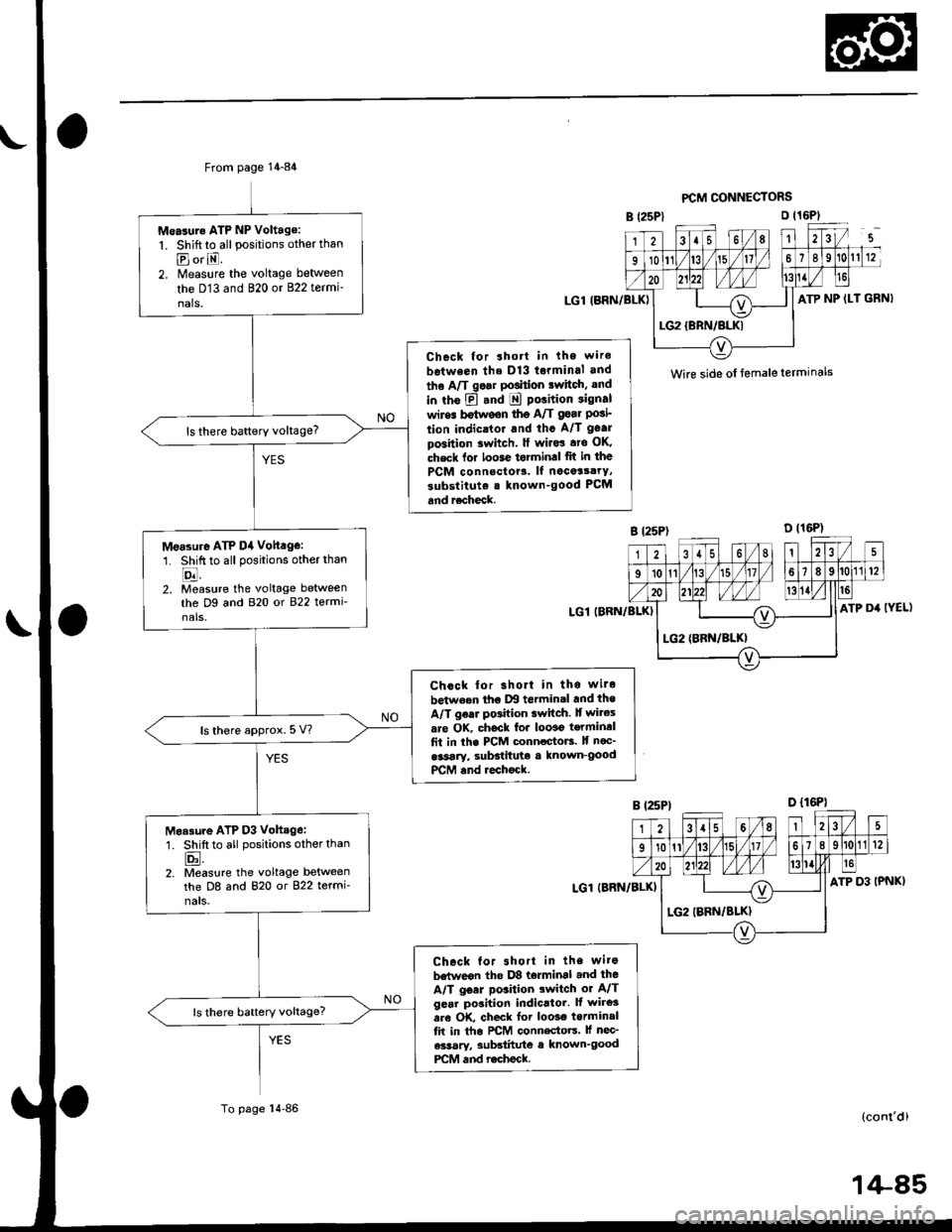
From page 14-84
Measule ATP NP Voltage:
1. Shift to all positions other thanpl or E.2. Measure the voltage between
the D13 and 820 or 822 termi-
nals.
Check for ahott in lhe wire
between ths D13 torminal and
tho A/T go.r PGition iwitci, and
in rho E .nd E polition signal
wires Mwgon tho A/T gsar Posi'tion indicrtor and th. A/T gGar
po3ition 3witch. ll wiJ.! .ro OK,
check lor loose torminal fit in the
PCM connoctor3. lf nocet3.rY,
substitute . known-good PCM
and r6check.
ls there baftery voltage?
Measure ATP D4 voh.g€:
1. Shiftto all positions otherthan
E2. Measure the voltage between
the Dg and 820 or 822 termi-nals.
Ch.ck lor 3hort in ths wilo
betweon tho lxl termin.l and tho
A/T ge.r pGhion switch. It wites
are OK. chock fo. looao t€rminal
fit in the PCM conn.ctoB. lf noc_
.*sary, sulFtitute a known-goodPCM .nd rechock.
ls there approx. 5 V?
Moa3ure ATP D3 Vohsge:
1. Shift to all positions other than
tr.2. Measure the voltage betweenthe D8 and 820 or 822 termi-
nals.
Check tor 3hort in the wits
betweon the D8 torminal and the
A/T goer position switch or A/Tgcar position indicltor. It wires
are OK, check for loo3€ torminalfit in tho FCM conn€ctoG. lf nec_
a3$ry, 3ubatitute e known'goodPCM and r.check.
ls there battery voltage?
To page l4'86
PCM CONNECTORS
o t16PlB {25P)
LGl (BRN/BLK)
g t25P)
LGl (BRN/8IJ()
LGl IBRN/BLK)
GRN)
D t16P)
IYEL)
231115 l68 112tV-s-
10n\/t7/ 167I910 t12
I
o zlzz /l/1,/ 113TIL---{O--l\=/LG2{BRN/BLKI
,/t\_
\a t9
ATP NP (LT
Wirc side o{ female termlnals
31158ll25
910111/t6l/17ls lt la112
20) W Wl/l '3111/ll
+LG2 (BBN/BLKI
-<_
ATP D4
LG2 (BRN/BLK}
14-85
Page 764 of 2189
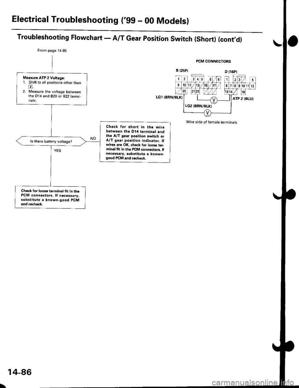
ElectricalTroubleshooting ('gg - 00 Models)
Troubleshooting Flowchart - A/T Gear position Switch (Short) (cont,dl
LGl (BRN/BLK}
FCM CONNECTORS
B {25P)D l16Pl
12[Ll81235
9101/113/ 151/)11789t0112,/ 20
ATP 2 {BLUI
Wire side of female terminals
Measule ATP 2 Vohage:1. Shift to all positions other thanl
2. Measure the voltage betweenthe D14 and 820 or 822 termi-nals,
Check for short in the wirebetween the D14 terminal andthe A/T gear position switch orA/T ge.r position indicator. Itwires aae OK, check loa loose ter-minal th in ths PCM connectors. llnecessary, substitute a known-good FCM and recheck.
ls there battery voltage?
Ch6ck for loose terminal fit in thePCM connoctors. lf necessary,substitute a known-good PCMand recheck.
\
14-86
Page 769 of 2189
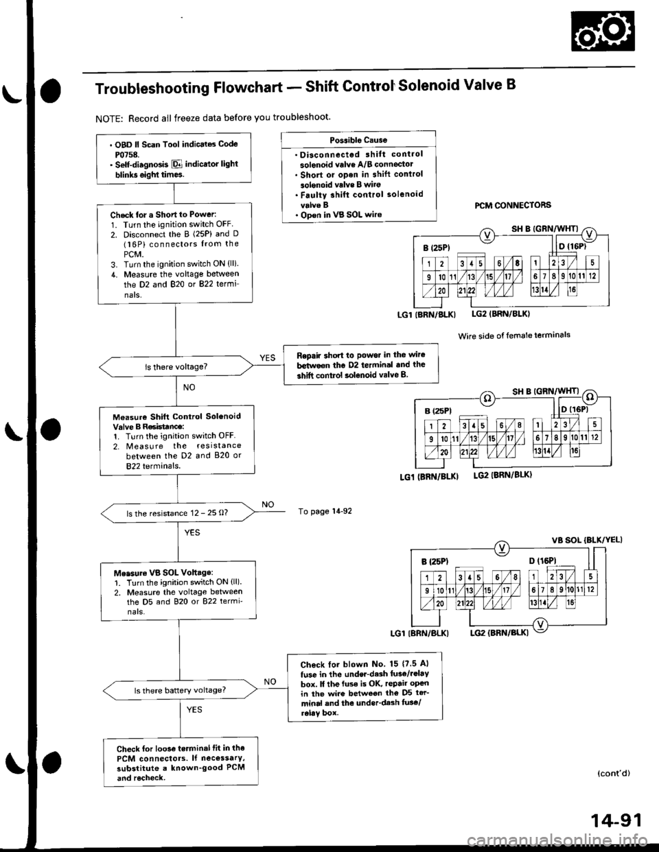
Troubleshooting Flowchart - Shift ControtSolenoid Valve B
NOTE: Record all freeze data before you troubleshoot.
Possiblg Cause
. Disconnectgd ihilt control
solenoid valve A/B conneciotr Short or oDen in shift conlrol
3olgnoid vrlve B wito. Faulty 3hift control solenoid
velve B. Op€n in VB SOL wirercM CONNECTORS
LGlIBRN/BLKI LG2IBRN/BLK)
Wire side of {emale terminals
LGi (BRi|/BLKILG2 IBRN/8LK)
To page 14-92
(cont'd)
14-91
. OBD ll Scan Tool indic.l6 Code
P0758.' Self-diagnosb El indicator light
blinks eighl tim6.
Check tor a Shortto Power:
1. Turn the ignition switch OFF
2. Disconnect the B (25P) and D(16P) connectors from the
PCM.3. Turn the ignition switch ON (lli.
4. Measure the voltage between
the D2 and 820 or 822 termi
nals,
Repaft 3hon to Powor in the wir€
b€tirvoon the D2 termin.l and the
3hift control solenoid valve B.
M€asure Shift Control SolenoidValve B R6isttnce:1. Turn the ignition switch OFF
2. Measure the resistance
between the D2 and 820 or
822 terminals.
ls the resistance 12 - 25 O?
Me.sure VB SOL Vohage:1. Turn the ignition switch ON (ll).
2. Measure the voltage betweenthe D5 and 820 or 822 termi'
nars.
Check lol blown No 15 {7.5 Al
fuse in the under-d.sh luae/rolav
box. ll the fuse is OK, repair open
in ihe wire between tho D5 ter-
minal and the under'dash fus€/relav box.
ls there battery voltage?
Check for loo3e terminal fit in the
PCM connectols. lf necossarY,
substitute a known_good PCM
and rocheck,
B (25Pt - I lD {16P)
B {25P1 D (t6Pl
Page 782 of 2189
ElectricalTroubleshooting ('99 - 00 Modelsl
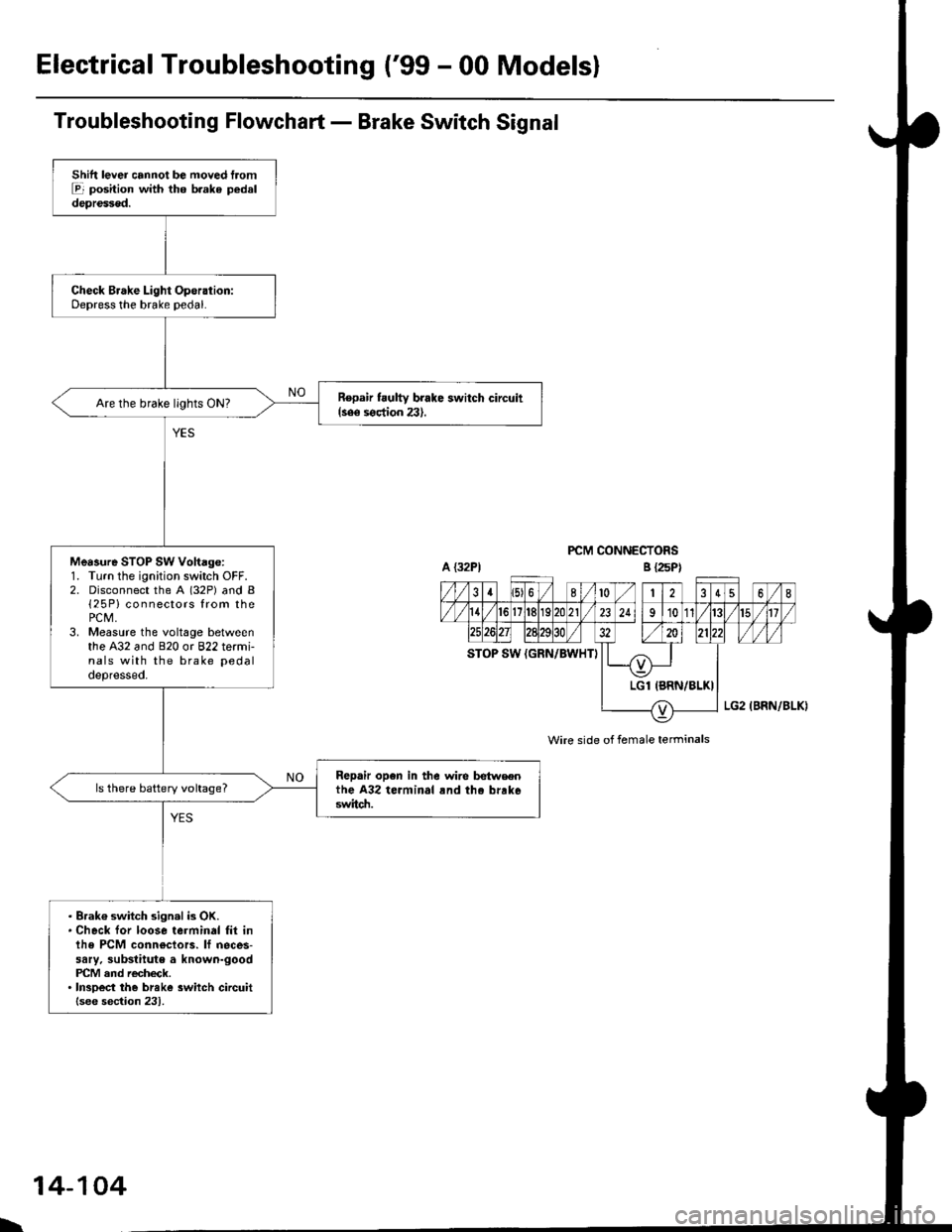
Troubleshooting Flowchart - Brake Switch Signal
PCM CONNECTORS
Wire side of female terminals
Shift lever cannot be moved tromE position with tho b.ake pedaldepressod.
Check Brake Light Operation:Depress the brake pedal.
Repair t ulty brake switch circuit{see s€ction 23}.Are the brake llghts ON?
Mea3ure STOP SW Vohage:1. Turn the ignition switch OFF.2. Disconnect the A (32P) and B{25P} connectors from thePCM,3. Measure the voltage betweenthe A32 and 820 or 822 termi-nals with the brake pedal
depressed.
Repair open in the wire betwsenthe A32 terminal rnd tho brrk6switch.
ls there battery voltage?
. Brak€ switch sign.l is OK.. Check for loose terminal fil inlhe PCM conn€ctors. lf neces-sary. substitute a known-goodPICM and recheck.. InsDect the breke 3witch circuitlsee section 231.
B {25P)
\
14-104
Page 783 of 2189
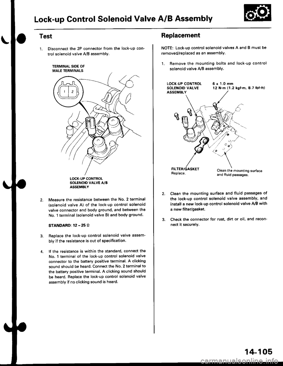
Lock-up Gontrol Solenoid Valve A/B Assembly
Test
'1, Disconnect the 2P connector from the
trol solenoid valve 1y'8 assembly.
TERMINAL SIOE OF
MALE TERMINALS
tocK-up con-
LOCK.UP CONTROLSOLENOID VALVE A/BASSEMBLY
Measure the resistance between the No. 2 terminal
(solenoid valve A) of the lock-up control solenoid
valve connector and body ground, and between the
No. 1 terminal (solenoid valve Bl and body ground.
STANDARD: 12 - 25 O
Replace the lock-up control solenoid valve assem-
bly if the resistance is out of specification.
lf the resistance is within the standard, connect the
No. 1 terminal of the lock-up control solenoid valve
connector to the battery positive terminal. A clicking
sound should be heard. Connsct the No. 2 terminal to
the battery positive terminal. A clicking sound should
be heard. Replace the lock-up control solenoid valve
assembly if no clicking sound is heard.
Replacement
NOTE: Lock-up control solenoid valves A and I must bs
removed/replaced as an assembly.
1. Remove the mounting bolts and lock-up control
solenoid valve Ay'B assemblv.
6 r 1.0 mm12 N.m (1.2 kgf.m,8.7 lbl.ftl
/:'-
Clean the mounting surfaceand fluid psssages.
Clean the mounting surface and fluid passages of
th6 lock-up control solenoid valve assembly, and
instsll a new lock-up control sol€noid valve Ay'B with
a new filtsr/gask€t.
Check the connector for rust, dirt or oil, and racon-
nect it securely.
1+105
Page 784 of 2189
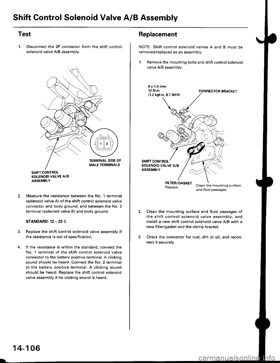
Shift Control Solenoid Valve A/B Assembly
Test
1. Disconnect the 2P connector from the shift control
solenoid valve A,/B assemblv.
SHIFT CONTROLSOLENOID VALVE A/B
ASSEMBLY
N4easure the resistance between the No. 1 terminal(solenoid valve A) of the shift control solenoid valve
connector and body ground, and between the No. 2
terminal (solenoid valve B) and body ground.
STANDARD: 12 - 25 O
Replace the shift control solenoid valve assembly if
the resistance is out of specification,
lf the resistance is within the standard, connect the
No. 1 te.minal of the shift control solenoid valve
connector to the battery positive terminal. A clicking
sound should be heard. Connect the No. 2 terminal
to the battery positive terminal. A clicking sound
should be heard. Replace the shift control solenoid
valve assembly if no clicking sound is heard.
14-106
Replacement
NOTE: Shift control solenoid valves A and B must be
removed/replaced as an assembly.
1. Remove the mounting bolts and shift control solenoid
valve A,/B assembly.
5xL0mm12 N.m(1.2 kgf.m,8.7 lbf.ft)CONNECTOR BRACKET
FILTER/GASKETBeplace.Clean the mounting surfaceand fluid passages.
Clean the mounting surface and fluid passages of
the shift control solenoid valve assembly, and
install a new shift control solenoid valve Ay'B with a
new filter/gasket and the clamp bracket.
Check the connector for rust. dirt or oil. and recon-
nect it securelv,