ESP HONDA CIVIC 1998 6.G Repair Manual
[x] Cancel search | Manufacturer: HONDA, Model Year: 1998, Model line: CIVIC, Model: HONDA CIVIC 1998 6.GPages: 2189, PDF Size: 69.39 MB
Page 1115 of 2189
)
Steering Rack Reassembly
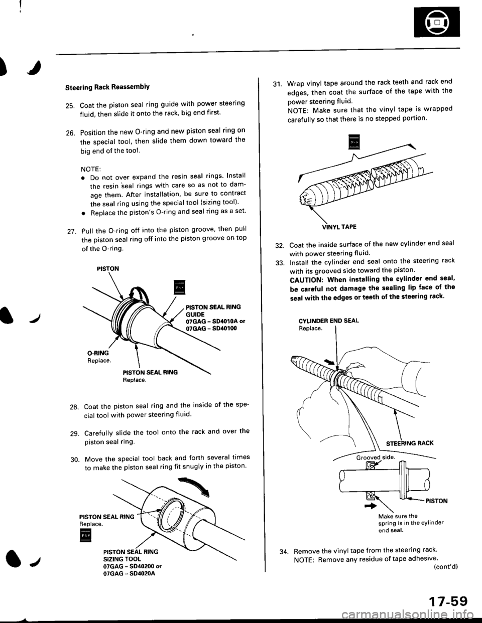
25. Coat the piston seal ring guide with power steering
fluid, then slide it onto the rack, big end first'
26. Position the new O-ring and new piston seal rlng on
the special tool, then slide them down toward the
big end of the tool
NOTE:
. Do not over expand the resin seal rings lnstali
the resin ;eal rings with care so as not to dam-
age them. After installation, be sure to contract
the seal ring using the specialtool (sizing tool)
. Replace the piston's O-ring and seal ring as a set'
27. Pull the O-ring off into the piston groove, then pull
the piston seal ring off into the piston groove on top
ol the O-ring
PISTON SEAL RINGGUIDE07GAG - SD4O10A ol
07GAG - SD,ol(xt
Coat the piston seal ring and the inside of the spe-
cial toolwith power steering fluid.
Carefully slide the tool onto the rack and over the
piston seal ring.
Move the special tool back and forth several times
to make the piston seal ring fit snugly in the piston'
PISTONReplace.
E
PISTON
31. Wrap vinyl tape around the rack teeth and rack end
edges, then coat the surface of the tape with the
power steering fluid
NOTE: Make sure that the vinyl tape is wrapped
carefully so that there is no stepped portion
Coat the inside surface of the new cylinder end seal
with power steering fluid.
Install the cylinder end seal onto the steering rack
with its grooved side toward the piston.
CAUTION: When installing the cylinder end seal,
be caieful not damage the sealing lip face of tho
seal with the edgss or teeth of th€ ste€ring rack'
CYLINDER END SEAL
Make sure thesPring is in the cylinder
end soal
Remove the vinyl tape from the steering rack
NOTE: Remove any residue oftape adhesive(cont'dl
17-59
Page 1117 of 2189
)
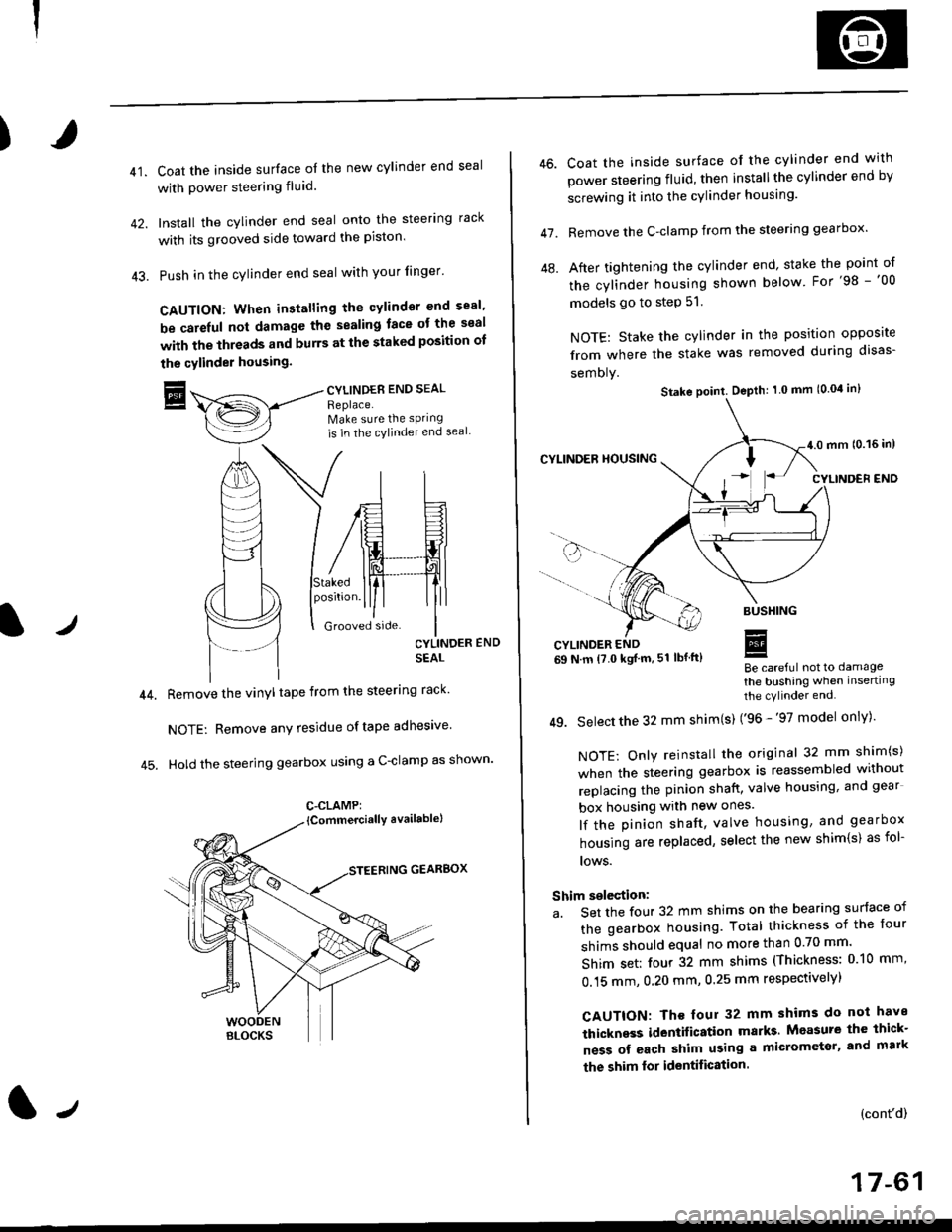
41.Coat the inside surface of the new cylinder end seal
with power steering fluid.
Install the cylinder end seal onto the steering rack
with its grooved side toward the piston'
Push in the cylinder end seal with your finger'
CAUTION: When installing the cylinder end sesl'
be carelul not damage the sealing face ot the seal
with the threads and burrs at the staked position oI
the cylinder housing.
trCYLINDES END SEAL
Replace.Make sure the sPring
is in the cylincler end seal
CYLINDER END
SEAL
Remove the vinyl tape from the steering rack'
NOTE: Remove any residue oftape adhesive
Hold the steering gearbox using a C-clamp as shown'
GEARBOX
C-CLAMP:
l-,
46.
47.
Coat the inside surface of the cylinder end with
power steering fluid, then installthe cylinder end by
screwing it into the cylinder housang.
Remove the C-clamp from the steering gearbox'
After tightening the cylinder end' stake the point of
the cylinder housing shown below For'98 -'00
models go to step 51.
NOTE: Stake the cylinder in the position opposite
from where the stake was removed during disas-
semoly.
Be careful not to damage
the bushing when inserting
the cylinder end.
49. Select the 32 mm shim(s) ('96 -'97 model only)'
NOTE: Only reinstall the original 32 mm shim(s)
when the steering gearbox is reassembled without
replacing the pinion shatt, valve housing, and gear
box housing with new ones.
lf the pinion shaft, valve housing, and gearbox
housing are replaced, select the new shim{s) as fol-
lows.
Shim selection:
a. Set the four 32 mm shims on the bearing surface of
the gearbox housing. Total thickness of the four
shims should equal no more than 0 70 mm'
Shim set: four 32 mm shims (Thickness: 010 mm'
0.15 mm, 0.20 mm, 0.25 mm respectivelyl
CAUTION: Th€ four 32 mm shims do not have
thickness identification marks Measure the thick-
ness of each shim using a micrometsr, and mark
the shim lor identification.
(cont'd)
17-61
Stake point. Depth: 1 0 mm (0.04 in)
Page 1134 of 2189
Front Suspension
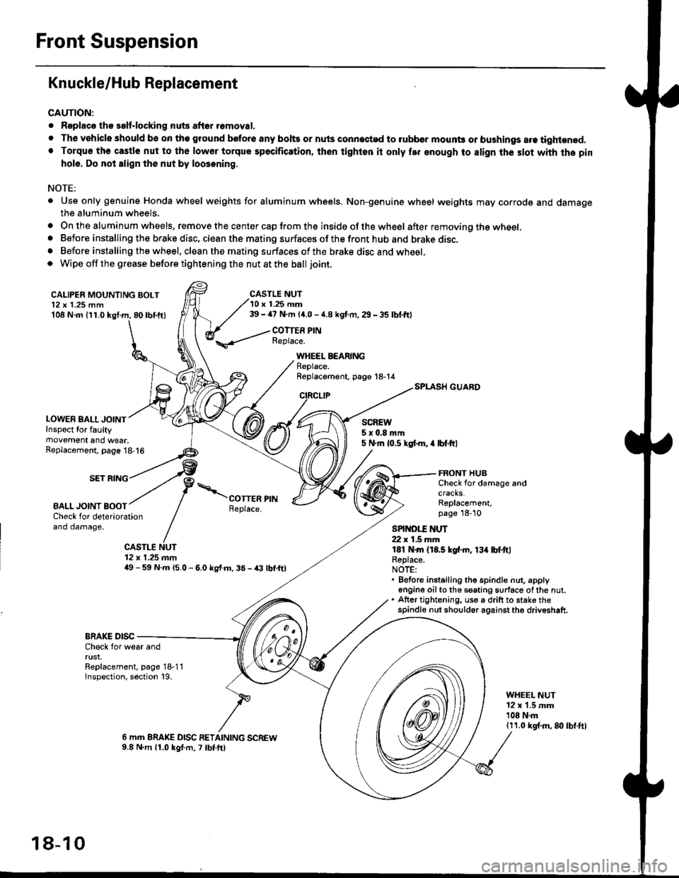
Knuckle/Hub Replacement
CAUTION:
. Replaco tho salf-locking nuts after romoval.
. The vehiclo should be on tho ground bsfore any bohs or nuls connected to rubber mounb or bushings are tightened.. Torqu€ th€ castle nut to the lowor torque specification, ihen tighton it only far enough to align th€ slot whh the pin
hole. Do not align the nut by loosening.
NOTE:
. Use only genuine Honda wheel weights for aluminum wheels. Non-genuine wheel weights may corrode and damagethe aluminum wheels.
. On the aluminum wheels, remove the center cap from the inside of the wheel after removing the wheel,. Before installing the brake disc, clean the mating surfaces of the front hub and brake disc,. Before installing the wheel, clean the mating surfaces of the brake disc and wheel.o Wipe off the grease before tightening the nut at the ball joint.
CALIPER MOUNTING BOLT12 x 1.25 mm108 N.m {11.0 kgl.m, 80lbf.ft)
LOWER BALL JOINTInspect for faultymovement and wear.
CASTLE NUT10 r 1.25 mm39 - ia7 N.m (4.0 - 4.8 kgf.m, 29 - 35 lbf,ftl
COTTER PINReplace.
WHEEL BEARINGReplace.Replacement, page 18-14
CIRCLIP
SCREW5x0.8mm5 N.m {0.5 ksl.m, 4 lbf.ftlReplacement, page 18-16
SET RING
BALL JOINT BOOT
FRONT HUBCheck for damage andcracks.Replacement,page 18-10Check for deteriorationand damage.
CASTLE NUT12 x 1.25 mm49 - 59 N.m l5.O - 6.0 kg{.m. 36 - /(} lbf,ftl
SPINDI.T ]{UT22 r 1.5 mmlEl N.m {18.5 kgf.rn, 13{ lbl.ttlReplace.NOTE:. Before instelling the spindle nut. apply6n9ine oilto th6 seating surface ofthe nut.. Atter tightening, uso a drift to stake thespindle nut should6r against the driveshaft.
BRAKE DISCCheck for wear andrust.Replacement, page 18-11lnspection, section 19.
WHEEL NUT12 x 1.5 mm'108 N.m1r1.0 kgf.m, 8lt lbf.ft)
6 mm BRAKE DISC RETAINING SCREW9.8 N.m 11.0 kgf.m, 7 lbtft)
18-10
Page 1176 of 2189
Master Cylinder/Brake Booster
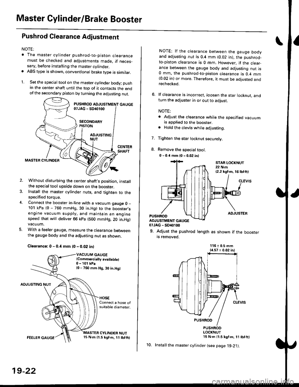
Pushrod Glearance Adjustment
NOTEr
. The master cylinder pushrod-to-piston clearancemust be checked and adjustments made, if neces_sary, before installing the master cylinder.. ABS type is shown, conventional brake type is similar.
1. Set the special tool on the master cylinde. body; push
in the center shaft until the top of it contacts the endofthe secondary piston by turning the adjusting nut.
Without disturbing the center shaft's Dosition, installthe specialtool upside down on the booster.Install the master cylinder nuts, and tighten to thespecified torque.
Connect the booster in-line with a vacuum gauge O _
101 kPa (0 - 760 mmHg, 30 in.Hg) to the booster,sengine vacuum supply, and maintain an enginespeed that will deliver 66 kpa (500 mmHg, 20 in.Hg)vacuum.
With a feeler gauge. measure the clearance Detweenthe gauge body and the adjusting nut as shown.
Clearance: 0 - 0.4 mm {0 - 0.02 in)
VACUUM GAUGE(Comm€rcially availeblel0 - 101 kPa{0 - 760 mm Hg, 30 in.Hg)
AOJUSTING NUT
FEELER GAUGE
19-22
10.
NOTE: lf the clearance between the gauge bodyand adjusting nut is 0.4 mm (0.02 in), the pushrod-to-piston clearance is 0 mm. However, if the clear_ance between the gauge body and adjusting nut is0 mm, the pushrod-to-piston clearance is 0.4 mm(0.02 in) or more. Therefore, it must be adjusted andrechecked.
6. lf clearance is incorrect, loosen the star locknut, andturn the adjuster in or out to adjust.
NOTE;
. Adjust the clearance while the specified vacuumis applied to the booster.. Hold the clevis while adjusting.
Tighten the star locknut securely.
Remove the special tool.
0 - 0.4 mm (0 - 0.02 in)
7.
ADJUSTERPUSHRODADJUSTMENT GAUGE07JAG - SD('1(x)
9. Adjust the pushrod length as shown if the boosterrs removed.
STAR LOCKNUT22 N.m{2.2 kg,f.m, 16lbtft)
11610.5 mm{{.571 0.02 in)
PUSHRODLOCKNUT15 N.m 11.5 kgf.m, 11 tbtftl
Install the master cylinder {see page l9-21).
Page 1182 of 2189
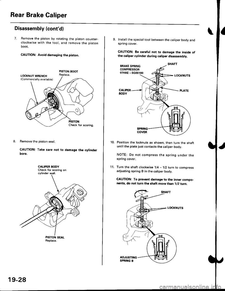
Rear Brake Galiper
Disassembly (cont'd)
7. Remove the piston by rotating the piston counter-clockwise with the tool, and remove the piston
boot.
CAUTION: Avoid damaging the piston.
PISTON BOOTReplace.
Remove the piston seal.
CAUTION: Take care not to damage the cylinderbore.
CALIPER BODYCheck for scoring on
9. Install the special tool between the caliper bodv andspnng cover.
CAUTION: Be caretul not to damags the inside ofthe caliper cylinder during caliper disassembty.
BRAKE SPRINGCOMPRESSOR07HAE - SG00100
11.
LOCKNUTS
Position the locknuts as shown. then turn the shaftuntil the plate just contacts the caliper body.
NOTE: Do not compress the spring under thespring cover.
Turn the shaft clockwise 1/4 -'ll2 tu.n to comoressadjusting spring B in the caliper body.
CAUTION: To preyant damage to the inner compo-nonts. do not turn the shaft mor€ than 1/2 turn.
SHAFT
LOCKNUTS
PISTON SEALReplace.
ADJUSTII{GSPRING 8
19-28
Page 1246 of 2189
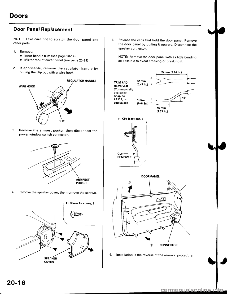
Doors
Door Panel Replacement
NOTE: Take care not to scratch the door panel andother pa rts.
'1. Remove:
. Inner handle trim (see page 20-14). Mirror mount cover panel (see page 20-24)
2. lf applicable, remove the regulator handle bypulling the clip out with a wire hook.
REGULATOR HANDLE
WIRE HOOK
Remove the armrest pocket, then disconnect thepower window switch connector.
ARMRESTPOCKET
4. Remove the speaker cover, then remove lhe screws.
3.
I
>: Screw locations, 3
| 6b:a,'
L"_
COVER
20-16
TRIM PADREMOVER(Commercially
available)Snap-on#A'177, orequivalent1mm{0.04 in.)
5. Release the clips that hold the door panel. Removethe door panel by pulling it upward. Disconnect thespeaker connector.
NOTE: Remove the door panel with as little bendingas possible to avoid creasing or breaking it.
.L12 fim(0.47 in.) T-
>: Clip locations,
l^
J[
=l$
ll,\*
atr-
,,)
REMoVER tl-)
11.77 in.l
O) CONNECTOR
6. lnstallation is the reverse of the removat oroceoure.
DOOR PANEL
Page 1253 of 2189
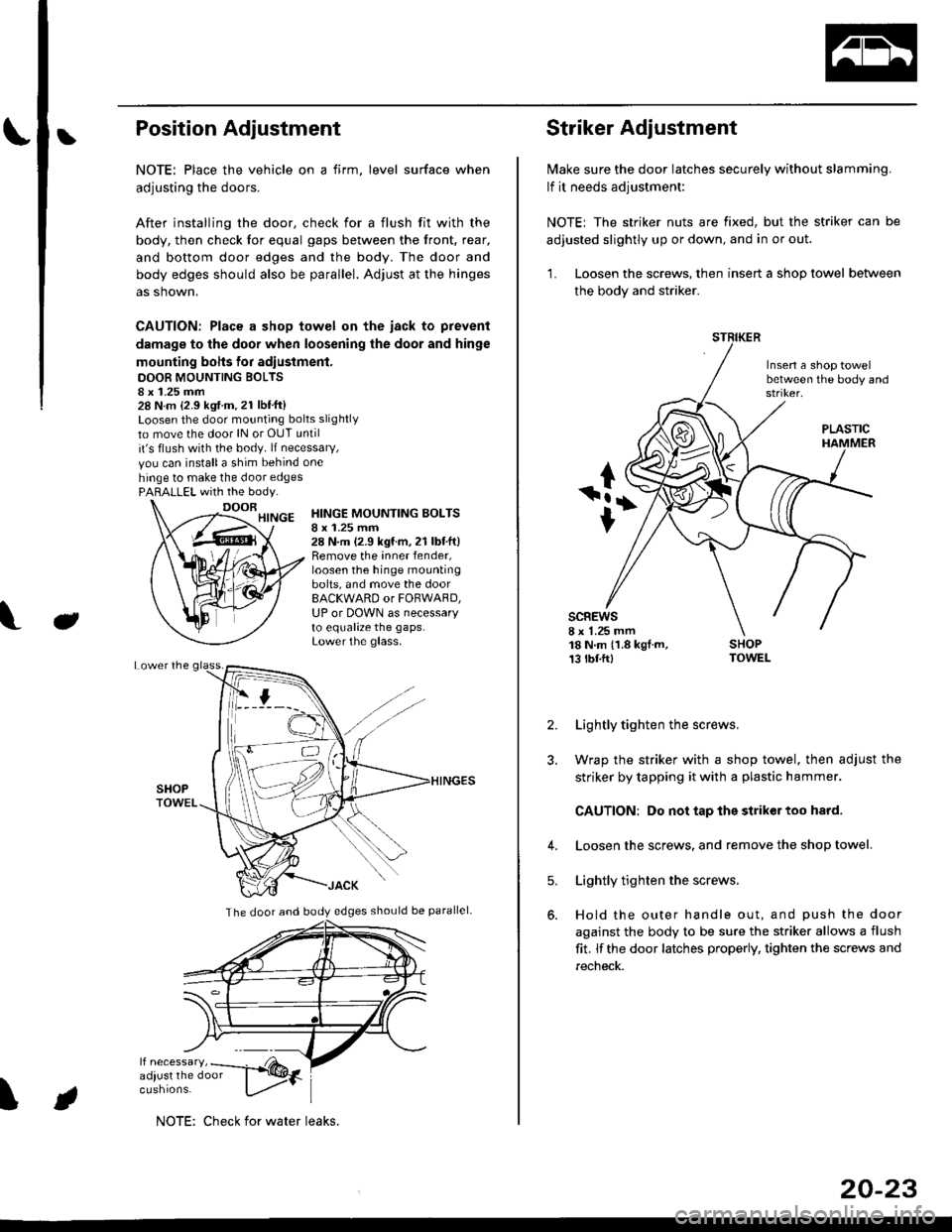
bPosition Adjustment
NOTE: Place the vehicle on a firm, level surface when
adjusting the doors.
After installing the door, check for a flush fit with the
body, then check for equal gaps between the front, rear,
and bottom door edges and the body. The door and
body edges should also be parallel. Adjust at the hinges
as shown,
CAUTION: Place a shop towel on the iack to prevent
damage to the door when loosening the door and hinge
mounting bohs for adiustment.
DOOR MOUNTING BOLTS8 x 1.25 mm28 N.m {2.9 kgf.m.21 lbt'ft}Loosen the door mounting bolts slightly
to move the door lN or OUT until
it's flush with the body. lf necessary,
vou can installa shim behind one
hinge to make the door edgesPARALLEL with the body.
J
HINGE MOUNTING BOLTSI x 1.25 mm28 N.m (2.9 kgf.m,21 lbtft)Remove the inner fender,loosen the hinge mountingbolts, and move the doorBACKWARD or FORWARD,UP or DOWN as necessaryto equalize the gaps.Lower the glass.
\
The door and body edges should be parallel-
ifF t
NOTE: Check for water leaks.
20-23
Striker Adjustment
lvlake sure the door latches securely without slamming.
lf it needs adjustment:
NOTE; The striker nuts are fixed, but the striker can be
adjusted slightly up or down, and in or out.
'L Loosen the screws, then insert a shop towel between
the body and striker.
Insert a shop towelbetween the body and
sc8Ews8 x 1.25 mm18 N.m (1.8 kgf.m,13 tbtftl
PLASTIC
2. Lightly tighten the screws.
3. Wrap the striker with a shop towel, then adjust the
striker by tapping it with a plastic hammer.
CAUTION: Do not tap the striker too hard.
4. Loosen the screws. and remove the shop towel.
Lightly tighten the screws.
Hold the outer handle out, and push the door
against the body to be sure the striker allows a flush
fit. lf the door latches properly, tighten the screws and
recheck.
5.
Page 1371 of 2189
Seat Belts
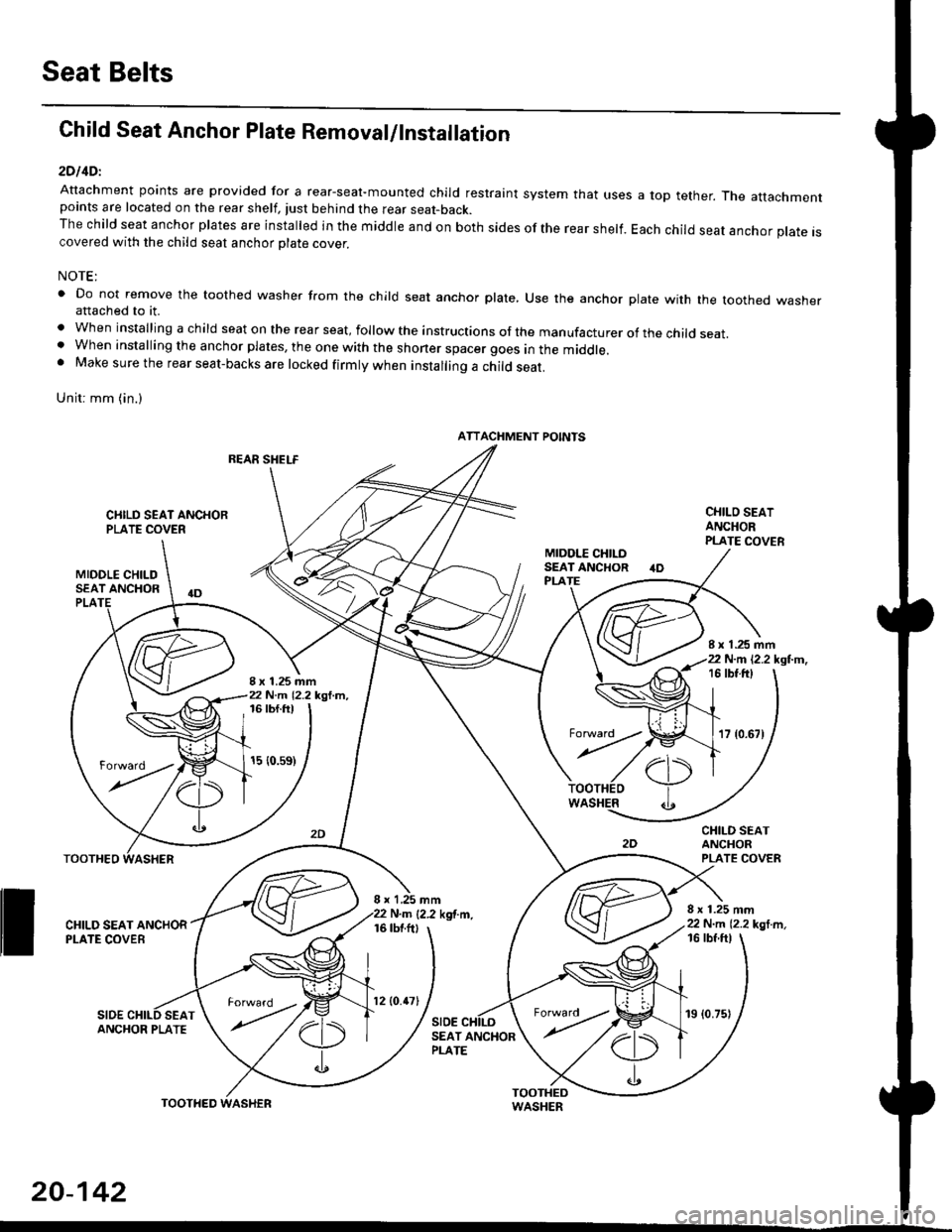
Child Seat Anchor Plate Removal/lnstallation
2DllDl
Attachment points are provided for a rear-seal-mounted child restraint system that usespoints are located on the rear shelf, tust behind the rear seat-back.The child seat anchor plates are installed in the middle and on both sides of the rear shelf.covered with the child seat anchor olate cover.
a top tether. The attachment
Each child seat anchor plate is
NOTE:
' Do not remove the toothed washer from the child seat anchor plate, Use the anchor plate with the toothed washerattached to it.
. When installing a child seat on the rear seat, follow the instructions of the manufacturer of the child seat.. When installing the anchor plates, the one with the shoner spacer goes in the middle.. Make sure the rear seat-backs are locked firmly when installing a child seat.
Unit: mm (in.)
REAR SHELF
CIIILD SEAT ANCHORPLATE COVER
MIDOLE CHILDSEAT ANCHOR
CHILO SEATANCHORPLATE COVER
CHILD SEATANCHORPLATE COVER
8 x 1.25 mm22 N.m 12.2 kgl m,
PLA
8 x 1.25 mm22 N.m 12.2 kgl.m,
I x 1.25 mm22 N.m 12.2 kgl.m,16 tbt.ftt
17 {0.67)
16 tbf.ft)
15 {0.s9)
WASHER
rl)
.t
TOOTHEO
ll ff*,".rd,',i"'"o*
SIDESEAT
I x 1,25 mmN.m {2.2 kgf.m.16 tbtftl
SIDE
16 tbf ftl
ANCHOR PLATESEAT ANCHORPLATE
ATTACHMENT POINTS
torward .
20-142
TOOTHED
12lO.47l19 (0.75)
Page 1474 of 2189
Troubleshooting
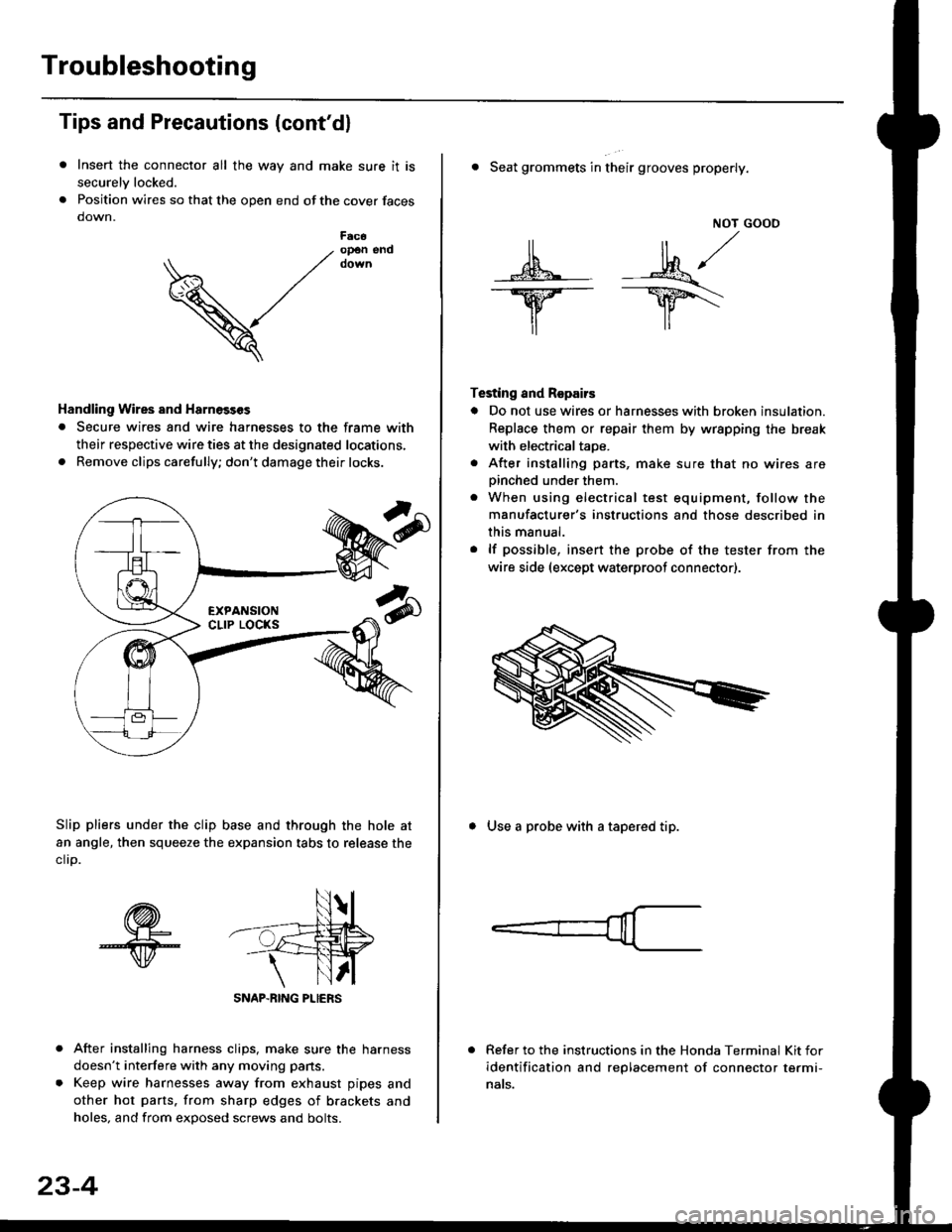
Tips and Precautions (cont'dl
Insert the connector all the way and make sure it is
securelv locked.
Position wires so that the open end of the cover faces
down.
After installing harness clips, make sure the harness
doesn't interfere with any moving pans.
Keep wire harnesses away from exhaust pipes and
other hot parts. from sharp edges of brackets and
holes, and from exDosed screws and bolts.
V
F6c6op€n end
Handling Wires and Harnosscs
. Secure wires and wire harnesses to the frame with
their respective wire ties at the designated locations,
. Remove clips carefully; don't damage their locks.
Slip pliers under the clip base and through the hole at
an angle, then squeeze the expansion tabs to release the
clrp.
SNAP-BING PLIERS
23-4
NOT GOOO
ll il,/
s*' -.1}8."/_Y--_Y5\
il ,,
Testing and Repairs
o Do not use wires or harnesses with broken insulation.
Replace them or repair them by wrspping the break
with electricaltaoe.
. After installing parts, make sure that no wires arepinched under them.. When using electrical test equipment, follow the
manufacturer's instructions and those described in
this manual.
. lf possible, insert the probe of the tester from the
wire side (except waterproof connector).
. Seat grommets in their grooves properly.
. Use a probe with a tapered tip.
Refer to the instructions in the Honda Terminal Kit for
identification and replacement of connector termi-
nats.
Page 1819 of 2189
How To Use This Manual
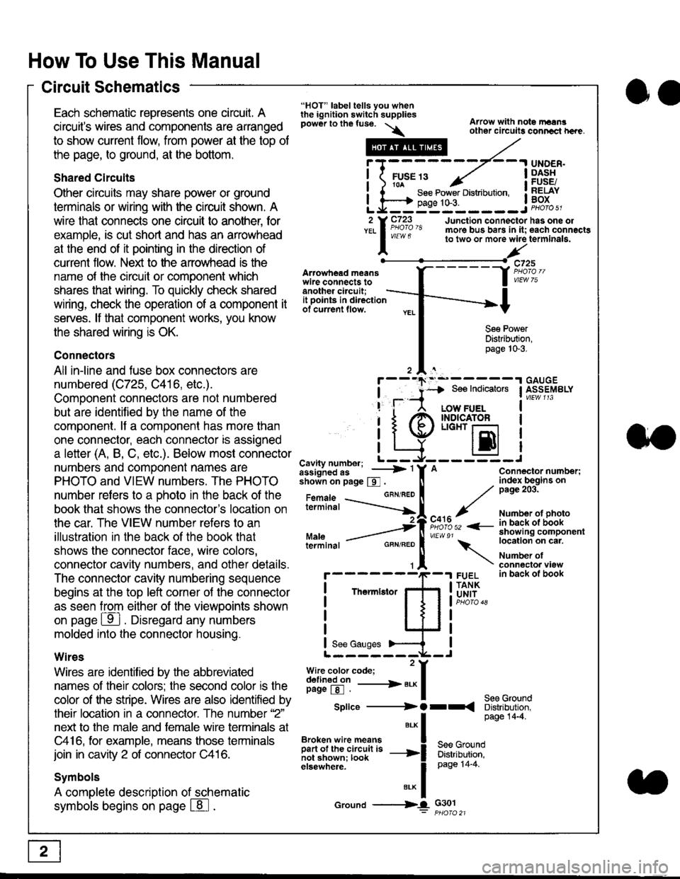
Circuit Schematics
oa
Each schematic represents one circult. A
circuit's wires and components are arranged
to show current flow, from power at the top of
the page, to ground, at the bottom.
Shared Circuits
Other circuits may share power or ground
terminals or wiring with the circuit shown. A
wire that connects one circuit to another, for
example, is cut short and has an arrowhead
at the end of it pointing in the direction of
current flow. Nelit to the anowhead is the
name o{ the circuil or comoonent which
shares that wiring. To quickly check shared
wiring, check the operation of a component it
serves. lf that component works, you know
the shared wiring is OK.
Connectors
All in-line and fuse box connectors are
numbered (C725, C416, etc.).
Component connectors are not numbered
but are identiJied by the name of the
component. lf a componenl has more than
one connector, each connector is assigned
a letter (A, B, C, etc.). Below most connector
numbers and comDonent names are
PHOTO and VIEW numbers. The PHOTO
number refers to a Dhoto in the back of the
book that shows lhe conneclor's location on
the car. The VIEW number refers to an
illustration in the back of the book that
shows the connector face, wire colors,
connector cavity numbers, and other details.
The connector cavity numbering sequence
begins at the top left corner oJ the connector
as seen from either of the viewooints shown
on page ffl . Disregard any numbers
molded into the connector housino.
Wires
Wires are identilied by the abbreviated
names of their colors; the second color rs the
color of the stripe. Wires are also identified by
their location in a connector. The number '2"
next to the male and female wire terminals at
C416, for example, means those terminals
join in cavity 2 of connector C416.
Symbols
A complete description of schematic
symbols begins on page | 8
"HOT" label tells you whenthe ignition switch suppliespower to the fuse. \
Artowhead meanswire connects toanother circuit;
Arrow with note rErngother circuils conncct h€re.
it .a
llu":: ^,{ ii t See Power Distribution, .I t----t oaqe tO-3. IL*--:--------J2 Y C723 Junction connectorYEL I Pao'o'8 more bus bars in it;
I - " " to two or more wire
l,/
-t>?
See PowerDistribution,page 10-3.
UNDER.DASHFUSE/RELAYBOX
has one oleach connactgterminala.
it ooints in directionof current flow.
TheImletor
t_I
Cavity number; L ---
Jiili'iJi!--' -----> '
shoin on page S .
Maleterminal
L?*?l?,-
"'"'I
c725
vlEUt/ 75
Connector number;index begins onpage 203.
Number ot photoin back ol bookshowing componentlocation on cat.
Number ofconneclor viewin back of book
7
GBN/FEO
See Ground
Soe Indicators I ASSEMBLY
:-------J
LOW FUELINDICATOFLIGHT r-l
EI
A
"o'r"/PHOTO 52 <-
\
FUELTANKUNIT
Splice ---------) O rr
".* I Page 14'4'
IBroken wire means | --^ -
iar";J.'It,;,rJ;ii; -----i Bffi,Bili*l
elsewhere. I 0a0e tn-a
IBrK Icround --->lL c301: ptioro 21