ESP HONDA CIVIC 1998 6.G Manual PDF
[x] Cancel search | Manufacturer: HONDA, Model Year: 1998, Model line: CIVIC, Model: HONDA CIVIC 1998 6.GPages: 2189, PDF Size: 69.39 MB
Page 1824 of 2189
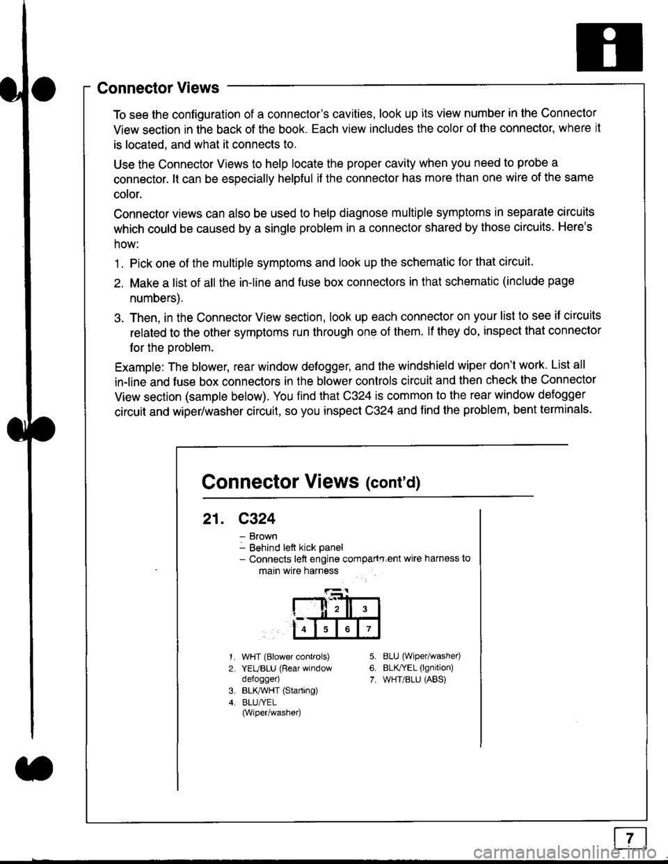
Connector Views
To see the configuration of a connector's cavities, look up its view number in the Connector
View section in the back of the book. Each view includes the color of the connector, where it
is located, and what it connects to.
Use the Connector Views to help locate the proper cavity when you need to probe a
connector. lt can be especially helpful if the connector has more than one wire of the same
cotor.
Connector views can also be used to help diagnose multiple symptoms in separate circuits
which could be caused by a single problem in a connector shared by those circuits. Here's
how:
1. Pick one of the multiple symptoms and look up the schematic for that circuit.
2. Make a list of all the in-line and fuse box connectors in that schematic (include page
numbers).
3. Then, in the Connector View section, look up each connector on your list to see il circuits
related to the other symptoms run through one of them. lf they do, inspect that connector
for the oroblem.
Example: The blower, rear window defogger, and the windshield wiper don't work. List all
in-line and fuse box connectors in the blower controls circuit and then check the Connector
View section (sample below). You find that C324 is common to the rear window defogger
circuit and wiper/washer circuit, so you inspect C324 and find the problem, bent terminals.
5.
6.
7.
1.
2.
WHT (Blower controls)
YEUBLU (Rear window
defogger)
BLK,ryVHT (Starting)
BLU/YEL(Wiper/washe0
8LU (Wiper/washed
BLfiEL (lgnition)
WHT/BLU (ABS)
Connector Views (cont'd)
21. C324
Brown
Behind left kick panel- Connects left engine compartry'ent wire harness to
main wire harness
ll,ll,
567
Page 1842 of 2189
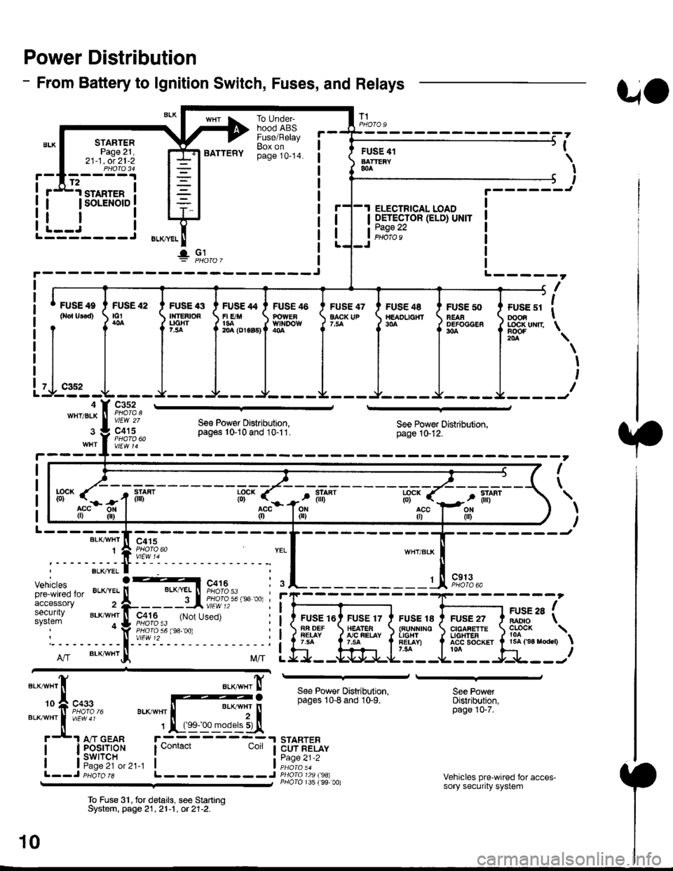
Power Distribution
- From Battery to lgnition Switch, Fuses, and Relays
STARTERPage 21,21-1, ot 21-2
.d1.ro"rr" i
I lsoLENorD I
FUSE 42tG1
BATTERY
To UndeFhood ABSFuse/RelayBox onpage 10-14.
FUSE 47EACK UP
T1
FUSE 41AATTEiY&A
I OETECTOR (ELD) UNIT
tii::.':
UO
PHOfO U
,
I
I
I
t.------J
ELECTRICAL LOAD
i--i rL---- J ELKml
!" Gl
FUSE 4e
0ro{ Urod)FUSE '13Ir|]EAtOAUGHT?.:ta
FUSE 46POWEaWll'IDOW
FUSE /t4
r| E/M1{rA204 (DrGa5)
FUS€ 48TtEADL|a}fT9|'A
FUSE 50NEAAOEFOCGER304
+------, f| ',
I ruse sr I oooa I
J LOC|( uNrr \
il-.4WHT/BLK
Itr '\
\
I
I
I
c352
vlEW 27
c415Se€ Pow€r Distribution,pag6s 10-10 and 10-11.See Power Distribution,page 10-12.
I
\
L------BLK/VI/HT
1
--------Jc415
Vehiclespre-wired foraccessorysecuritysystem
c913PHOTO 6A
FUSE 16AR DEFFEIAY
FUSE 17HEATEA!'/C FEIAY
FUSE 18{RUNNINOL|GHlFET.AY)7.54
FUSE 27CIGAFETTEL|oHTEAACC SOCKET ta
arse ra fBADIO \
?o?"* \15A ('94 raodcr)
ff".acc0)
llL--------J
See Power Distribution,pages 10-8 and 10-9.
STARTERCUT RELAYPage 21-2
P/lolo 135 (99 00)
See PowetDistribution,page 10-7.
Vehicles pre-wired for acces-sory security system
To Fuse 3'|, for delails, see StartrnqSystem, page 21,21-1 , ot 21-2. -
10
Page 1854 of 2189
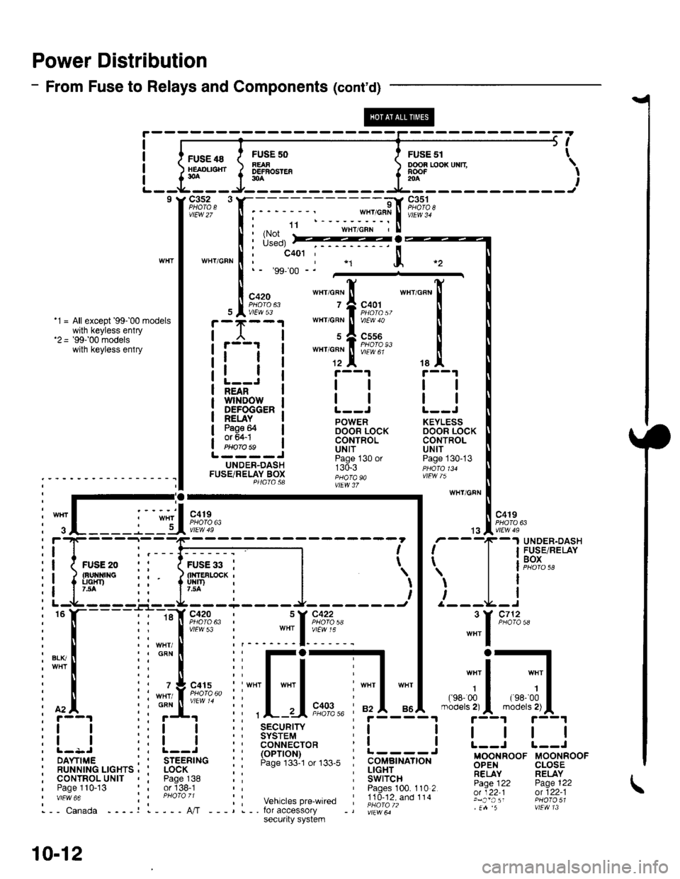
Power Distribution
- From Fuse to Relays and Components (cont'd)
FUSE 48HEAOL|SHT30A
c3s2 3
vtEw 27
WTIT/GFN
FUSF 50FEAFDEFBOSTEF30A
ooon r,ooxuxn \RooF -' I204
I
I
I
I
5t
FusE sr t
9l
;:$*fiit"rl.ru'"'""
I i*il
:::*ffi,
""'_[
tallt r--1 r--1
l-=Ji llll;i'ifr'ilrowi | | | |NEAN
DEFOGGER: L--J L--J
!EuI. ! powen KEYLEss
3g9F I oocin iocx DooR LocKI CONTROL CONTROLPHorobs ! Uttf UN|TL----J ii"j- , "n ^.UNDER-DASH r:d.r ppdro,uFUSETRELAY Box ;;;; "" ,!Fw /); - - - - - - ' - - - - - - - - - - I I P4atasa ;;"; i,
:-;-ry wHr/GFN
: I .-.-.i. -", I '-': :-'I "o''. I l "ott
i
";L____j_lU*?,?"
| .,"Iii;n*
: f'4. ii ;f' ii ,L-.-Ii"?,%' ;f5-"i4.-"'";5-{"'"r'!|L1
:! ! ::! ! :; 3$3i'9,1" r! ! I | | |
i l- l-
- - -
_:-
- ---------1 - - - - - - -
i I r'
- -
T
-
I F$r".',lP,XiI
ii{*"..0 ,' 1;;;il--l l | leox
i! ipp ii liuir'-*i |
')l 'l
l i' r--t-----'-.r--rL--------J- -------t I /---L-I
i
"
l-----l i ::[ir:;?:' i ::[?:+: |
"""1
'*'
i[.iiilr-il[-j,*---]d;1.*-;il;1,
:l I r:l I i: ts6'""?cro* i! ! L--i r--J
i ilr--,.ir...^.._^i I
'rr6-;i."
i: !:lJ',"#,",,*. i i.itc-,tr# Bgg,FooF u-oorinoor' RUNN|NG LrcHrs , ' LocK ; : ; !!gEr_.. ;;,1'y RELAYi cournol^urtr , i pase^138 :: i Swircn- -- Fj.Ti, pase 122, Paoe 110-13 or'138-1 Paoes 100. 110 2 -:Y;^:':;;;''"" :i ;hoi;,; ;: vehicrespre_wired ;!id-?iXioii.' glj:,';: ffl?3;1i,-- canada ----r l----A,/T ---,.-. for accessory -, |;r"*ir" .n 5 vtEvtl 13
10-12
secu.ity system
Page 1859 of 2189
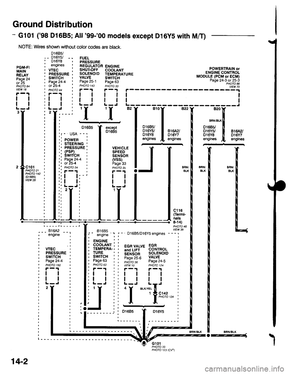
Ground Distribution
- Gl01 ('98 Dl685;All '99-'00 models except D16YS with M/T)
NOTE: Wires shown without color codes are black.
01685/_ D16Y5/ -.016Y8engrnes
.__-;,#'-_,--', engrne ;
, wEc: PRESSURE '
, swtTcH :I Page24-4 iI PHOTO 150: r -'l
:t | :
:l | :,L-J.
FUELPRESSUREREGULATOR ENGINESHUT.OFF COOLANTSOLENOID TEMPERATUREVALVE SWTTCHPage 25-1 Page 63PHOIO 143 PHOTA 33r-1F-.|
llll
lltlL-J L-J
POWERTRAIN olENGINE CONTROLMODULE (PCM or ECM)Page 24-3 ot 25-3PHOTO 86
----:y4
tl
tl
PGi,|.FIMAINRELAYPage 24ol 25
vlEw 18
tl
tl
3Y'I'I
excaptD1685
VEHICLESPEEDSENSOR(vss)Page 336FN/ELKERll/EIKcl01PHOTO 21PHOTO 142(o1685)vtEw 28
ct16Cferml-nals8n 4)
FltaFt( vttw 39t- .''iiti ' " D1685/D16Y5 engrnes ---'
t2
. ENGINE : :
i 933'?il-; i 5"T,Yf,*' 33i,"o, i
i lgfft" i I S.ir1".l^ soL€NorD :' Pase 63 : : ;;;;; - pase 24.i :' PHOTO 63 | | VtEWlO pHOIa124 ;, r-1 | , F-.t r-.r
:l | ;:l | ! | :;t | :,t | | | ;
j,f
ii T.__.,|,,,,,.
j
--
----- --l i otoas I Dr6y5 :
:------.1.--------.
14-2
o-----J
Page 1887 of 2189
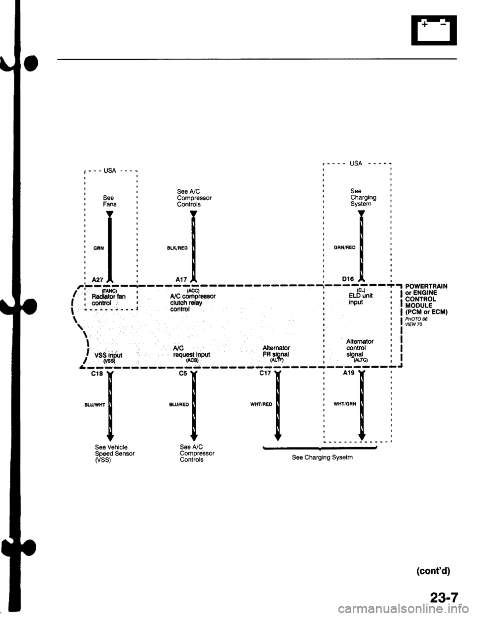
: , See ly'C ' See, See ' Compressor : Charging' Fans : Controls ; System
'YI Y:Y
:l: ll:[
il: l:l
i*"1 i "*"."1 : o"",".o1
, r | : -^*l
ili I i Ii. *, I i rrz.l, ; ot. I'.--..--r-
/i**fffi'* I r,rcffi"oro, i e.St*I ; cornrd ' clulcfi rday ' nput
| .-,---;---l COntrOl
\'
\;t ' Altsrnqtor! Nc Altemator : conrol
/, u.1;lf* roqrsr rnpd FRfrgd ; tSJ",
&rrr:rr
SeeCharornoSystein - :
Y:
!i
u".o I i
i:
o,. .!, iPOWERTRAIN
l*.]["n i 13'"',1+?3.': I MODULE; | (PcM or EcM)
i lw,t?'"
Altornstor ; Iconrol i I
$:--lJ
"''I
',n,-
I
I
See VehicleSpeed Sensorryss)
*[
".,^."
!
I
t
See NCCompressorControls
.r_l
See Charging Sysetm
(cont'd)
23-7
Page 1891 of 2189
![HONDA CIVIC 1998 6.G Manual PDF t)
POWERTRAINorENGINECONTROLMODULE(PCM or ECM)
BLKryVHT
fFUSE 15AL1EA|{A]OAsP sExsoa7.54See PowerDistribution,page 10-5.
UNDER.DASHFUSE/RELAYBOX
t\-I Secondary! HO2S input, (sf,o2sl-------
- ,.-"., -^ HONDA CIVIC 1998 6.G Manual PDF t)
POWERTRAINorENGINECONTROLMODULE(PCM or ECM)
BLKryVHT
fFUSE 15AL1EA|{A]OAsP sExsoa7.54See PowerDistribution,page 10-5.
UNDER.DASHFUSE/RELAYBOX
t\-I Secondary! HO2S input, (sf,o2sl-------
- ,.-"., -^](/img/13/6068/w960_6068-1890.png)
t)
POWERTRAINorENGINECONTROLMODULE(PCM or ECM)
BLKryVHT
fFUSE 15AL1EA|{A]OAsP sExsoa7.54See PowerDistribution,page 10-5.
UNDER.DASHFUSE/RELAYBOX
t\-I Secondary! HO2S input, (sf,o2sl-------
- ,.-"., -^,o"::.f=_
rtl
ll er-x'wnr
g A crer
""",".--*'i-"fj*"
c432
c7a2
-l--
:
$i
see Power
SECOND- F rl EVAPORATIVE ' f-tl-l EVAPORA- ;ARY I I I EMISSION 'I I ITIVE
8iiE,R I ltt l !'JiiABi*"'il ltt l Et,i"'J""sENsoR I Jll I soleHoro 'l )ll I i9x1661
!t"93:t IJJ vs!:", iLLl !Ailf*'",,
: I 'l"u.t
".*,^,'"rf I ,----j I l';i";?'*
2 J:--;t, C432 ll 96 model: all Coupesptlofo /6 i 97 model a
coupes,
BLKI"V!/HT
--1"r", 'Y :t f iiiv!3 Y iiol-o ao
onr.r wxr I I ll catrfornra Sedan ll 9 g c49 !s8 mocJr, iri I a il!9.!a^5?
""""._l**t' ,L-
r I i,,o"n,n",l "f,",ul,,
-"-.1,=l
;^[::Ttn*- I i I
""1
,
+ g:%,, *"[
il I :D13 A A5A A15 A , A2gA 428 |'-----=,-- -=-7-tsHo2sc) tso2sHTci {Pcs) | {vs!,) (2wBs)Sensor Secondary EVAP purge ' EVAP control EVAP bypassground HO2S hedter controisolenoid : canister vent solenoidt control valve control , shut valve valve controlt , conkglttb------
BLKAA/HT
BLKAVHT
1
c401
c568
BLKTIVHT
BIK
FED1
Distribution, '
page 10-5. :
, BLK' YEL
SHUT BLU
(Terminals 1-10)
vtEw 52
! Ii{:',+'i":
II
23-11
Page 1916 of 2189
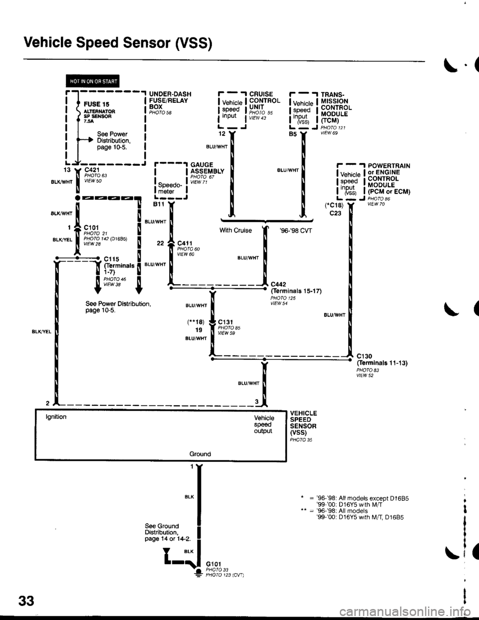
Vehicle Speed Sensor (VSS)
il';;---lI ALTENNATOA I
I I""::,",,", !
Lr_f1l_i
".*,1,[ 9#":1"
\.(
UNDER-DASHFUSE/RELAYBOXPHO|O 5a
I v"ni"t"
l:g9qd
iineilt i
12
CRUISECONTROLUNIT
vtEw 43
I v"ni"p I
l:p"gd I
I'T$, I
TRANS.MtsstoNCONTROLMODULE
FCM)
vtEw 69
! !iio',6T""f
EtuwHr|
!y:ll*!Bb'^i1?'J.'
! so""oo- ! iffiilr*J l;6';irtE!;i#:*! il il iiTs'l, iipEr',r"L---J I I L - J D.^..1*B11 Y [ [ (-C18) Y vtLNTo
l;i"i;'! [ [ l'ffi, liib-r,ro,ecu1
See Power Distribution,page 10-5.(
lgnitjonVohielespeeoouptn
Ground
Y' """-' Oerminats 1.t-13)
vlEw 52
VEHICLESPEEDSENSOR(VSS)PHATA 35
= '96- 98: Allmodels except D1685'99 00: D 1 6Y5 w th Lr/T= '96-'98: All models'99-'00: D16Y5 with M/I D1685
.i,
a33
Page 1921 of 2189
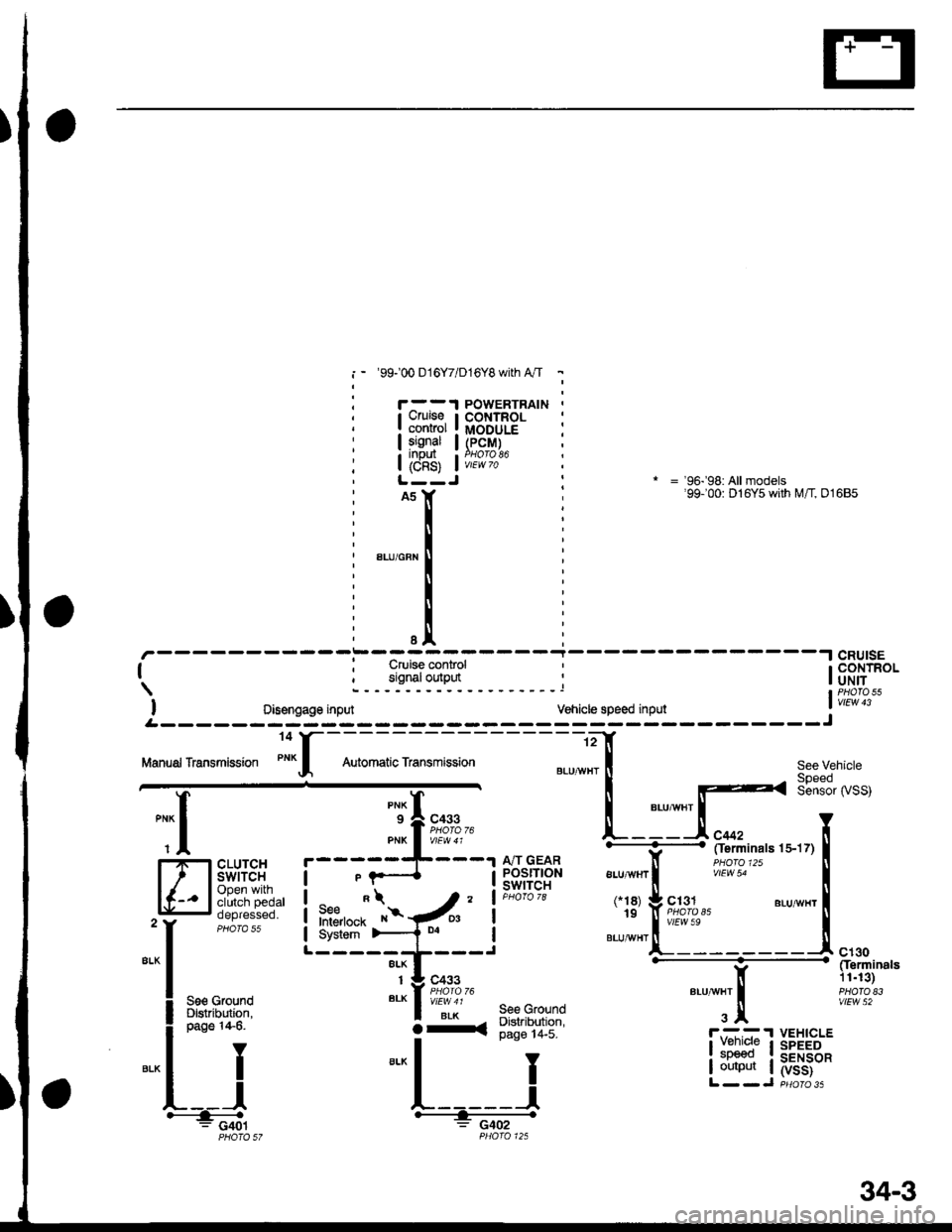
i - '99100 016Y7/D16Y8 with A"/T -
Cruiseconrolsgnal
i8s) i
iil
POWERTRAINCONTROLMODULE(PcM)
* = '96-'98: All models'99100: D16Y5 with M/T, 01685
-----i-----.lcRU|sE
| ; Cruise control ' I CONTROL
signaloutput ' |oNirI PHATO 55
I oisengage input vehicle speed input ' vtEw 13
.--------;---- ---J
See Vehicle
Sensor rySS)
See GfoundDigtribution,page 14-5.
I
J
"{
,--r-s=-.
CLUTCHswtTcHOpen withclutch pedaloepresseo.
A/T GEARPOSITIONswtTcH
L- ----
ALU,ryVHT
3x
ct30Cferminals11.13)PHATO E3vlEw 52See GrolndDlslribution,page 14-6.
IY
ll
L__l#: G401
lI:::1" I
I output I
VEHICLESPEEDSENSOR(vss)
O-a
34-3
Page 1922 of 2189
Gruise Control (cont'd)
- How the Circuit Works
The cruise control system uses mechanical and
electrical devices to maintain the car's sDeed at a
setting selected by the driver.
System Description
The cruise control unit receives command signals
from the crurse control main switch and the cruise
control SeVResume switch. With the ignition switch
in ON (ll) or START (lll), voltage is provided to the
cruise control main switch through fuse 14. When
you push the switch to ON, power is provided to the
cruise control unit and the brake switch.
The cruise control unit receives information about
operating conditions from the brake switch, the
vehicle speed sensor (VSS), and the clutch switch
(manual transmission) or the A,/T gear position
switch (automatic transmission). The cruise control
unit then sends signals to the cruise control actuator
which regulates the throttle position to maintain the
selected speed. The conlrol unit compares the
actual speed of the car to the selected speed. The
control unit then uses the result of that comoarison
to open or close the throttle.
The brake switch releases the system's control of
the throttle at the instant you press on the brake
pedal. The switch sends a signal to the control unit
by removing power from the normally closed brake
input (GRY wire), and providing power at the
normally open brake input (GRN/vVHT wire). The
control unit responds by allowing the throttle to
close. The clutch switch or the A,/T gear position
switch sends a "disengage" signal to the control unit
that also allows the throttle to close.
The cruise control system will set and automatically
maintain any speed above 25 mph (40 km/h). To set
it, make sure the main switch is on and the switch
indicator is on. Then, after reaching the desired
speed, press the SET switch. This sends a "set"
signal to the cruise control unit which, in turn,
controls the cruise control actuator to maintain the
set speed.
When you push the SET switch and the cruise
control system is on, the "cruise control" ON
indicator lights up.
34-4
(
You can cancel the cruise control system by
turning the main switch off . This removes power to
the control unit and erases the set speed from
memory. lf the system is disengaged temporarily
by the brake switch, or clutch switch, and the car's
speed is still above 25 mph, press the resume
switch: the car will automatically return to the
previously set speed.
For gradual acceleration without pressing the
accelerator pedal, push the RESUME switch and
hold it there. This will send an "acceleration" signal
to the control unit. When you release the switch, the
system will be reprogrammed for the new speed. To
slow the car down. oush the SET switch in and hold
it there. This sends a "deceleration" signal to the
control unit, causing the car to coast. When the
desired speed is reached, release the SET switch.
This reprograms the system tor the new speed.
Refer to the Service Manual (Section 23, Electrical)
tor specific tests or troubleshooting procedures.
(
a
Page 1923 of 2189
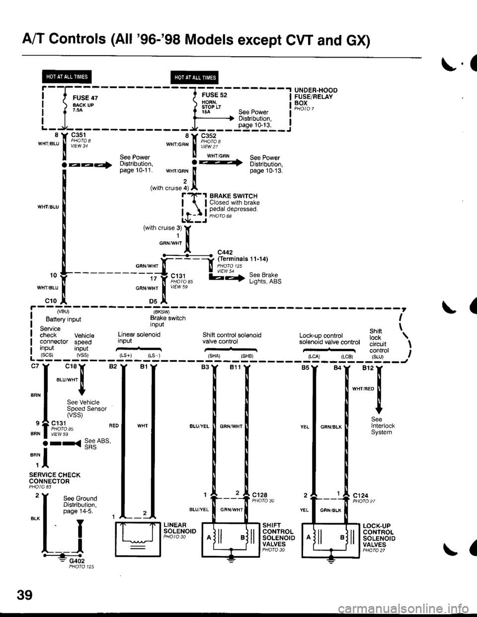
A/T Controls (All '96-'98 Models except CW and GX)
r.(
r5A see power I
--li$"i':,--iL-.At----- __*____..,,53-j"i__8 Y 93^s_1- 8Y C352'"'".u
I iii'i"' ""'o"* | i#?1o.'
ll see power ll wrr cnn See Power
la--- oisirioution, ! -t 6iri,iortion,
[--*
t"*tr*t1,'.':,:;i. wHr GFN lt page 10-13.
,i(with crurse 4) Al"'rl(-1 BRAKE swrrcH
| lClosed.with brake
Ir-I Il,?,|fll,"P'"""oL*--J
c18lr 82
"ar-"t I
I
See VehicleSpeed Sensor(vss)
ct31PHO|O 35vtEw 59
r< See ABs'
UNDER"HOODFUSE/RELAYBOXI
I
I
BFN
9
BFN
o
""il
SERVICE CHECKCONNECTOR
See GroundDistribution,page 14-5.
I
YEL
c124
L__lH:""".: G402
SHIFTCONTROLSOLENOIDVALVES
LOCK-UPCONTROLSOLENOIDVALVES
,. L ---- - - --.#ku" :::::'o f
---------tty"c;11,, l;-,f l;?t?:if,-:;tr *";.!, *"
c10 ,| Ds^'
I Lvou, (SKSV,
! Battery input Brake lwitch I
service nPUt ehin t;;;;i- Vehrcte Linear sotenoid Shift controt sol€noid Lock-up conkol iJ'[
'\
connector speed input valve conhol solenoid vatve controt tliiJ"it \uo trut tconrrol t: (scs) (vss) {Ls}) rLs ) {sHA' {SHB, (LCA) (LCB) {S-U) .--:-'--J
ct28
39
GFN/ALK
(