Mount HONDA CIVIC 1998 6.G Repair Manual
[x] Cancel search | Manufacturer: HONDA, Model Year: 1998, Model line: CIVIC, Model: HONDA CIVIC 1998 6.GPages: 2189, PDF Size: 69.39 MB
Page 785 of 2189
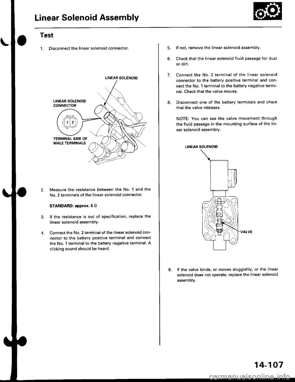
Linear Solenoid Assembly
Test
1. Disconnect the linear solenoid connector.
LINEAR SOLENOID
4.
Measure the resistance between the No. 1 and the
No. 2 terminals of the linear solenoid connector.
STANDARD: applox. 5 O
lf the resistance is out of specification, replace the
linear solenoid assembly.
Connect the No. 2 terminal of the linsar solenoid con-
nector to the batterv positive terminal and connect
the No. 1 terminal to the battery negative terminal A
clicking sound should be heard.
lf not, remove the linear solenoid assembly.
Check that the linear solenoid fluid passage Ior dust
or dirt.
Connect the No. 2 terminal of the linear solenoid
connector to the battery positive terminal and con-
nect the No, 1 terminal to the battery negative terma-
nal. Check that the valve moves.
Disconnect one of the battery terminals and check
that the valve releases.
NOTE: You can see the valve movement through
the fluid passage in the mounting surface of the lin-
ear solenoid assembly.
LINEAR SOLENOID
VALVE
lf the valve binds, or moves sluggishly, or the linear
solenoid does not operate, replace the linear solenoid
assembly.
1.
14-107
Page 786 of 2189
Mai nshaft/Cou ntershaft
Linear Solenoid AssemblySpeed Sensors
Replacement
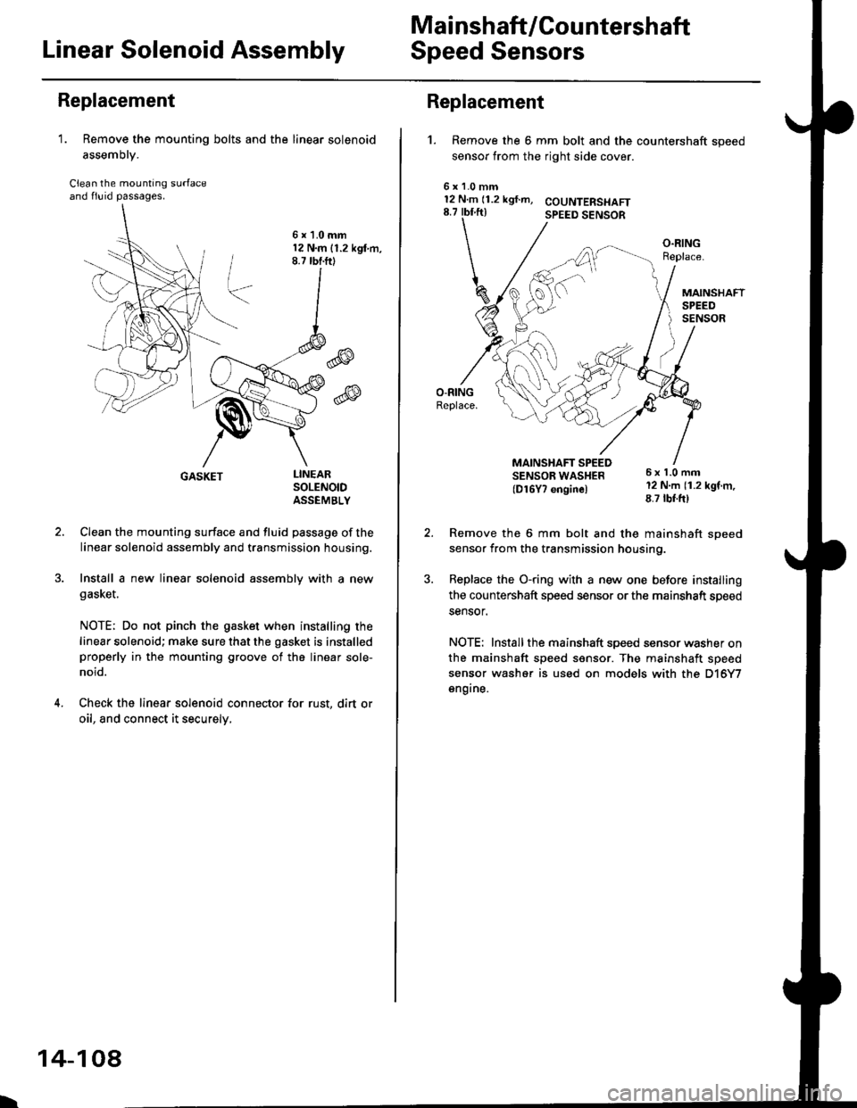
1. Remove the mounting bolts and the linear solenoid
assemory.
Clean the mounting surfaceand flu id passages.
6x1.0mm12 N.m 11.2 kgl m,8.7 tbf.ftl
@
@
GASKET
Clean the mounting surface and fluid passage of the
linear solenoid assembly and transmission housing.
Install a new linear solenoid assembly with a new
gasl(et.
NOTE; Do not pinch the gasket when installing the
linear solenoid; make sure that the gasket is installedproperly in the mounting groove of the linear sole-
noid.
Check the linear solenoid connector for rust, dirt or
oil, and connect it securely,
LINEARSOLENOIDASSEMELY
I
14-108
Replacement
't.
6x128.7
Remove the 6 mm bolt and the countershaft speed
sensor from the right side cover.
COUNTERSI{AFTSPEED SENSOR
O.RINGReplace.
MAINSHAFTSPEEDSENSOR
MAINSHAFT SPEEDSENSOB WAS}IER(D16Y7 enginel
6x1.0mm12 N.m (1.2 kgf m,8.7 tbf.ft)
1.0 mmN.m (1.2 kgf.m,rbf ft)
\\
/,
%/E:)
Remove the 6 mm bolt and the mainshaft sDeed
sensor from the transmission housino.
Replace the O-ring with a new one before installing
the countershaft speed sensor or th€ mainshaft speed
sensor.
NOTE: Installthe mainshaft speed sensor washer on
the mainshaft speed sensor. The mainshaft speed
sensor washer is used on models with the D'|6Y7
engine.
Page 790 of 2189
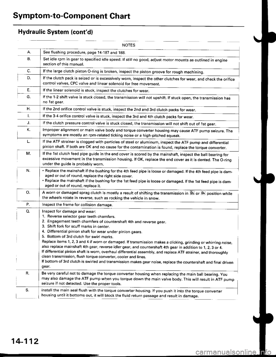
Symptom-to-Component Chart
Hydraulic System (cont'dl
G.
n,
set idle rpm in gear to specified idle speed. lf still no good, adjust motor mounts as outlined in enginesection of this manual.
lf the clutch pack is seized or is excessively worn. inspect the other clutches for wear, and check the orificecontrol valves, CPC valve and linear solenoid for free movement.
lf the linear solenoid is stuck, inspect the clutches for wear.
lmproper alignment or main valve body and torque converter housing may cause ATF pump seizure. Thesymptoms are mostly an rpm-related ticking noise or a high-pitched squeak.
lf the l st clutch feed pipe guide in the end cover is scored by the mainshaft, inspect the ball bearing forexcessive movement in the transmission housing. lf oK, replace the end cover as it is dented. The o-rinounder the guide is probably worn.
Replace the mainshaft if the bushing for the 4th feed pipe is loose or damaged. lf the 4th feed pipe is danFaged or out of round, replace the right side cover.
Replace the mainshaft if the bushing for the 1st feed pipe is loose or damaged. lf the 1st feed pipe is darn-aged or out of round, replace it.
A worn or damaged sprag clutch is mostly a result of shifting the transmission inthe wheels rotate in reverse, such as rocking the vehicle in snow.
or E position while
Inspect for damage and wear:
1. Reverse selector gear teeth chamfers.
2. Engagement teeth chamfers of countershaft 4th and reverse gear.
3. Shift fork for scuff marks in center.
4. Differential pinion shaft for wear u nder pin ion gears.
5. Bottom of 3rd clutch for swirl marks.
Replace items 1,2,3 and 4 if worn or damaged. lf transmission makes a clicking, grinding orwhirring noise,also replace mainshaft 4th gear, reverse idler gear. and countershaft 4th gear in addition to 1, 2, 3 or 4.lf differential pinion shaft is worn, overhaul differential assembly, and replace ATF strainer, and thoroughlyclean transmission, flush torque converter, cooler and lines.lf bottom of 3rd clutch is swirled and transmission makes gear noise, replace the countershaft and final drivengear.
Be very careful not to damage the torque converter housing when replacing the main ball bearing, you
may also damage the ATF pump when you torque down the main valve body. This will result in ATF pumpseizure if not detected. Use the oroper roors.
Install the main seal flush with the torque converter housing. lf you push it into the torque converterhousing until it bottoms out, it will block the fluid return passage and result in damage.
See flushing procedure, page 14-187 and 188.
lf the large clutch piston O-ring is broken, inspect the piston groove for rough machining.
lf the l-2 shift valve is stuck closed, the transmission will not upshift. lf stuck open, the transmission hasno 1st gear.
lf the znd orifice control valve is stuck. inspect the 2nd and 3rd clutch oacks for wear.
lf the 3-4 orifice control valve is stuck, inspect the 3rd and 4th clutch oacks for wear.
lf the clutch pressure control valve is stuck closed, the transmission will not shift out of 1st gear.
lf the ATF strainer is clogged with particles of steel or aluminum, inspect the ATF pump and differentialpinion shaft. lf both are OK and no cause for the contamination is found, replace the torque converter.
Inspect the frame for collision damage.
14-112
Page 801 of 2189
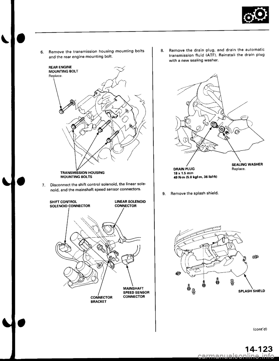
6. Remove the transmission housing mounting bolts
and the rear engine mounting bolt.
Disconnect the shift control solenoid, the linear sole-
noid, and the mainshaft speed sensor connectors'7.
SHIFT CONTROLSOLENOID CONNECTORLINEAR SOLENOIDCONNECTOR
MOUNTING BOLTS
BRACKET
8. Remove the drain plug, and drain the automatic
transmission fluid (ATF). Reinstall the drain plug
with a new sealing washer.
DRAIN PLUG18 x 1.5 mm'9 N m t5 o kgf'm' 36 lbf'ft|
9. Remove the splash shield.
Replace.
SPLASH SHIELD
{cont'd)
14-123
Page 802 of 2189
Transmission
Removal(cont'd)
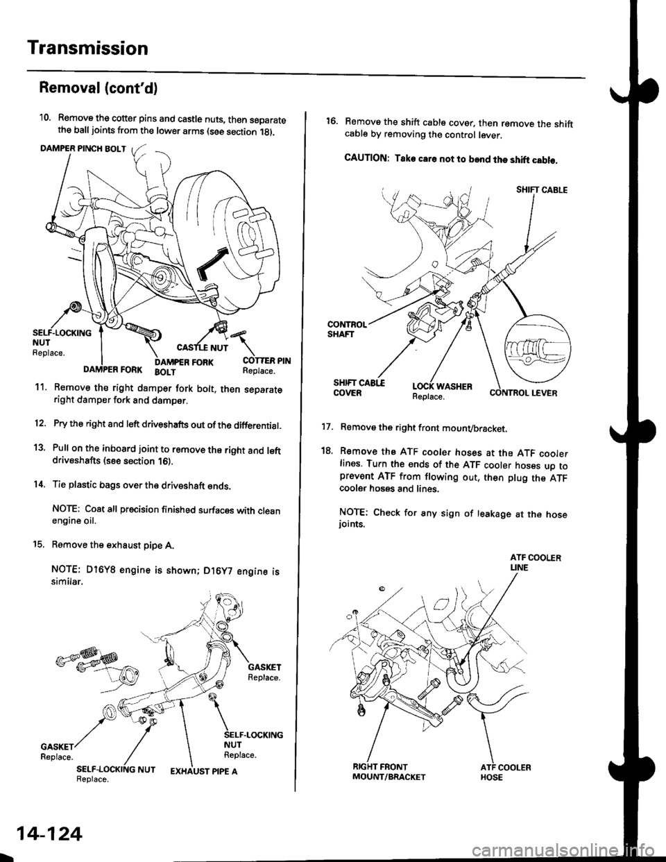
'10. Remove the cotter pins and castle nuts, th€n separatethe balljoints from the lower arms (see section 1gl.
DAMPER PINCH BOLT
NUT
FORI(FORK BOLT
11. Remove the right damper fork bolt. th€nright damper fork and dampor.
COTTER PINReplace.
separate
12.
1a
14.
Pry the right and left driveshafts out ofthe differential.
Pull on the inboard joint to remove the right and leftdrivsshafts (see section 16).
Tie plastic bags over the driveshaft onds.
NOTE: Coat all precision finished surfaces with cleanengine oil.
Remove the exhaust pipe A,
NOTE: Dl6YB engine is shown; D16y7 engine issimilar.
t9.
SELF-LOCKING NUTReplace.
L
14-124
EXHAUST PIPE AMOUNT/BRACKET
17.
18.
16. Remove the shift cable cover. then remove the shiftcable by removing the control lever,
CAUTION: Take car6 not to bond the shift cable.
Remove the right front mounvbracket.
Remove the ATF cooler hoses at the ATF coolerlines. Tufn the ends of the ATF cooler hoses uo toprevent ATF from flowing out, then plug the ATFcooler hosgs and lines.
NOTE: Check for any sign of leakage at the hoseioints.
WASHER
Page 803 of 2189
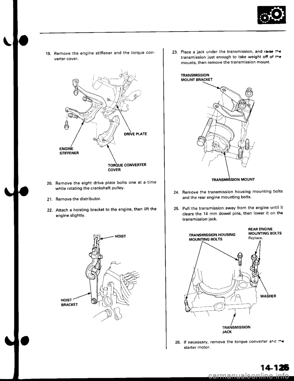
19. Remove the engine stiffener and the torque con-
verter cover.
Remove the eight drive plate bolts one at a tlme
while rotating the crankshaft pulley.
Remove the distributor.
Attach a hoisting bracket to the engine, then lift the
engine slightly.
HOISTBRACKET
20.
21.
COVER
23. Place a jack under the transmission. and ra6a :'.
transmission iust enough to take weight otf ol tF.
mounts. then remove the transmission mounl
TRANSMISSIONMOUNT BRACKET
Remove the transmission housing mounting bolts
and the rear engine mounting bolts.
Pull the transmission away from the engine until it
clears the 14 mm dowel pins, then lower it on the
transmission jack.
TRANSMISSION HOUSING
lf necessary, remove the torque converter anc:"
starter motor.
24.
25.
1+16
Page 812 of 2189
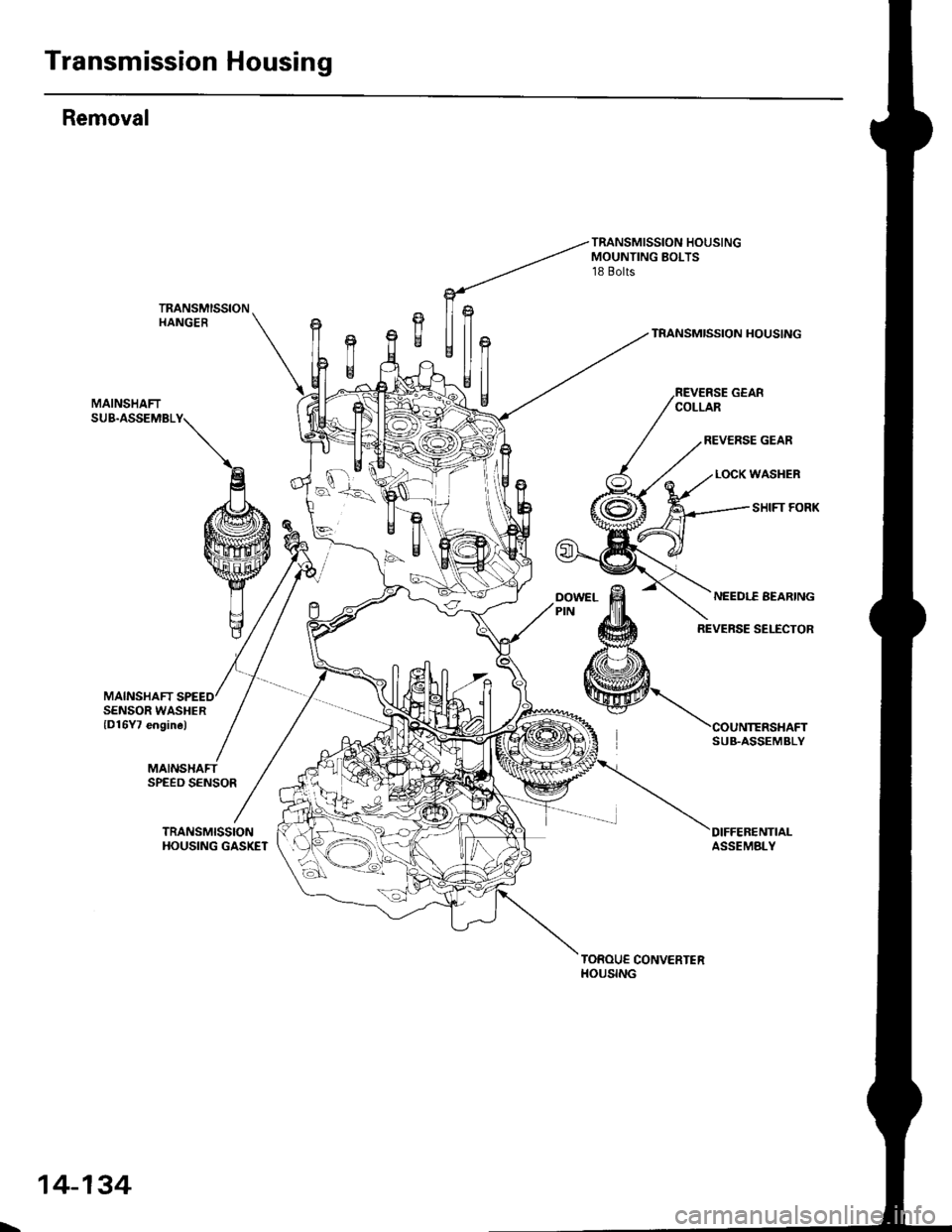
Transmission Housing
Removal
MAINSHAFT
TRANSMISSION HOUSINGMOUNTING BOLTS18 Bolts
TRANSMISSIONHANGERTRANSMISSION HOUSING
MAINSHAFTSUB.ASSEMBLY
SENSOR WASHERlD16Y7 engine)
MAINSHAFTSPEED SENSOR
TRANSMISSIONHOUSING GASKETDIFFEBENTIALASSEMBLY
TOROUE CONVERTERHOUSING
SUB.ASSEMBLY
L,
14-134
Page 856 of 2189
![HONDA CIVIC 1998 6.G Repair Manual Transmission
_\,]ffil
Reassembly (contd)
TRANSMISSIONHANGER
MAINSHAFTSUB.ASSEMBLY
*
Ufln
$*U ./
TRANSMISSION HOUSINGMOUNTING BOLTS10 x 1.25 mm4{ N.m {4.5 kg{.m,33 lbI.ft)
TRANSMISSION HOUSING
REVER HONDA CIVIC 1998 6.G Repair Manual Transmission
_\,]ffil
Reassembly (contd)
TRANSMISSIONHANGER
MAINSHAFTSUB.ASSEMBLY
*
Ufln
$*U ./
TRANSMISSION HOUSINGMOUNTING BOLTS10 x 1.25 mm4{ N.m {4.5 kg{.m,33 lbI.ft)
TRANSMISSION HOUSING
REVER](/img/13/6068/w960_6068-855.png)
Transmission
_\,]ffil
Reassembly (cont'd)
TRANSMISSIONHANGER
MAINSHAFTSUB.ASSEMBLY
*''
Ufln
$*U ./
TRANSMISSION HOUSINGMOUNTING BOLTS10 x 1.25 mm4{ N.m {4.5 kg{.m,33 lbI.ft)
TRANSMISSION HOUSING
REVERSE GEARCOLLAR
REVERSE GEAR
LOCK WASHER
SHIFT FORK
MAINSHAFT SPEEDSENSOR WASHER(D16Y7 engine)
MAINSHAFT
COUNTERSHAFTSUB.ASSEMBLY
OIFFER€NTIALASSEMBLY
SPEED
TRANSMISSIONHOUSING GASKET
TOROUE CONVERTERHOUSING
14-178
Page 857 of 2189
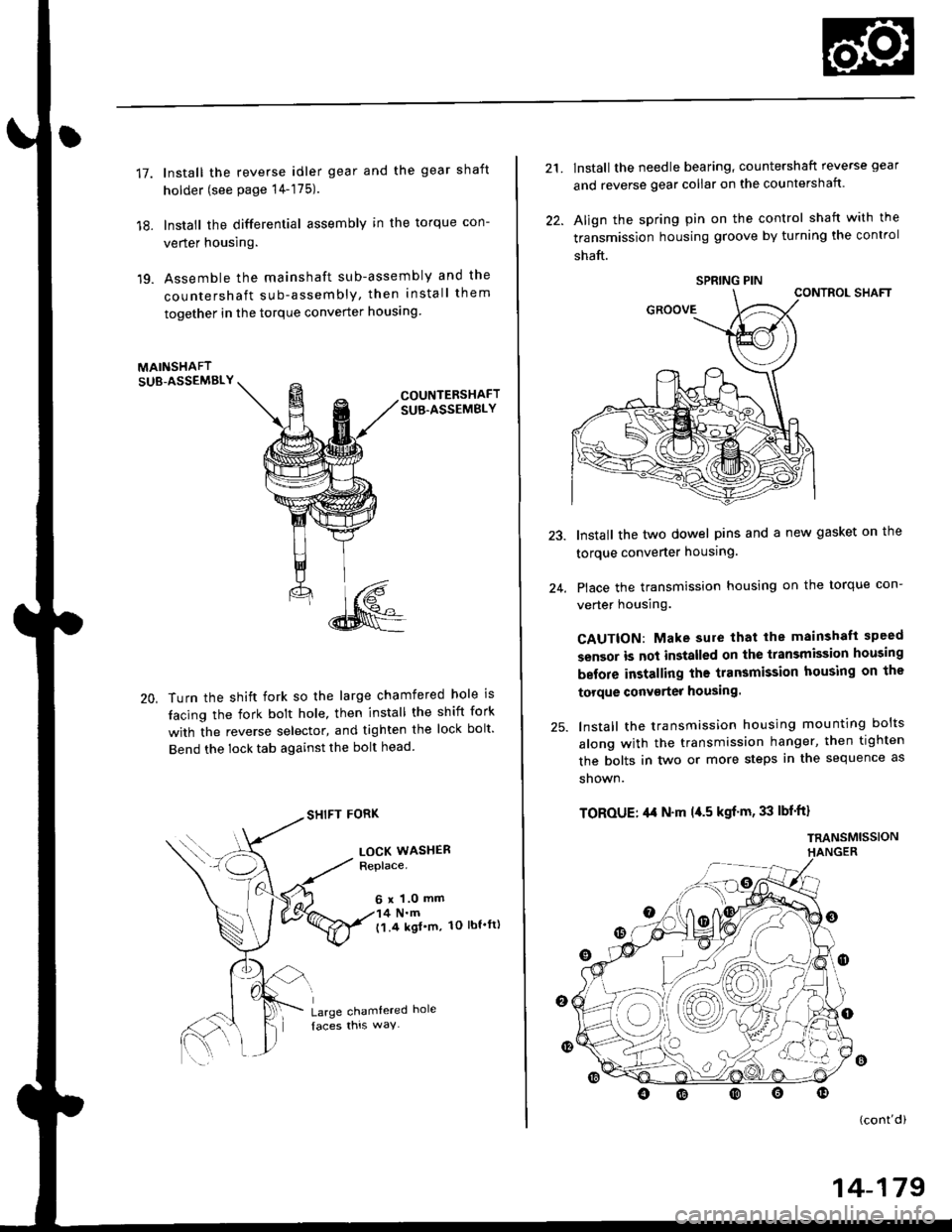
17.
18.
19.
lnstall the reverse idler gear and the gear shaft
holder (see page 14-175).
lnstall the differential assembly in the torque con-
verter housing.
Assemble the mainshaft sub-assembly and the
countershaft sub-assembly, then install them
together in the torque converter houslng
MAINSHAFTSUB-ASSEMBLY
20,
COUNTERSHAFTSUB.ASSEMBLY
Turn the shift fork so the large chamfered hole is
tacing the fork bolt hole, then install the shift fork
with the reverse selector, and tighten the lock bolt'
Bend the lock tab against the bolt head
SHIFT FORK
LOCK WASHERReplace.
6 x 1.0 mm4 N.m('l.4 kgl'm, 1O lbt'ft)
Large chamtered hole
21.
22.
lnstall the needle bearing, countershaft reverse gear
and reverse gear collar on the countershaft.
Align the spring pin on the control shaft with the
transmission housing groove by turning the control
shaft.
CONTROL SHAFT
Install the two dowel pins and a new gasket on the
torque converter housing.
Place the transmission housing on the torque con-
verter housing.
CAUTION: Make sure that lhe mainshaft speed
sensor is not installed on the transmission housing
before installing the transmission housing on the
torque conv€rter housing.
lnstall the transmission housing mounting bolts
along with the transmission hanger, then tighten
the bolts in two or more steps in the sequence as
shown.
TOROUE: ,l,t N'm l{.5 kgf'm, 33 lbf'ft}
TRANSMISSIONHANGER
24.
o
(cont'di
SPRING PIN
14-179
Page 861 of 2189
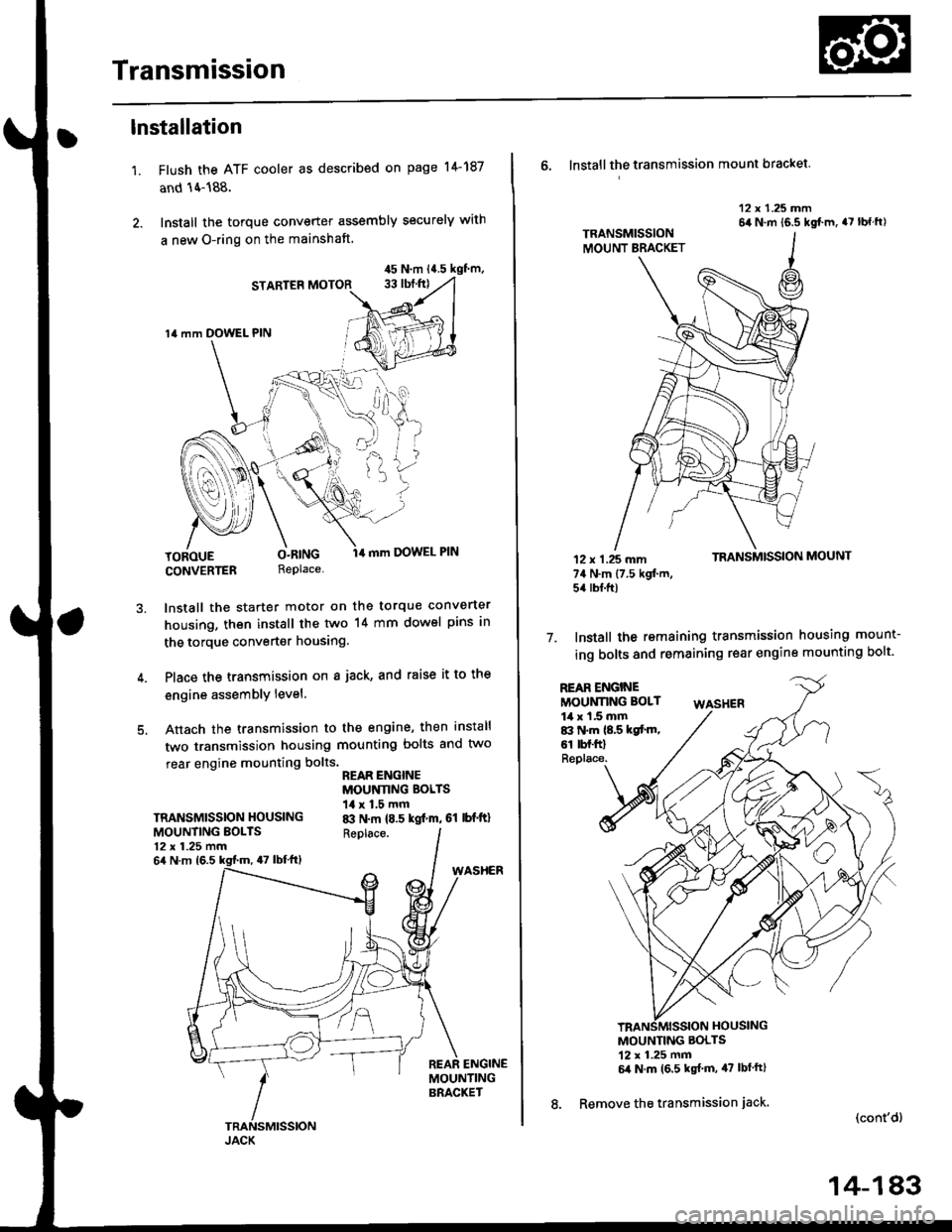
Transmission
1.
lnstallation
Flush the ATF cooler as described on page l4-187
and 14-188.
Install the torque converter assembly securely with
a new O-ring on the mainshaft
STARTER MOTOR
14 mm DOWEL PIN
TOROUE O-RING
CONVERTER Replace
lnstall the starter motor on
housing, then install the two
the torque converter housing.
lil mm DOWEL PIN
the torque converter
14 mm dowsl pins in
MOUNTINGBRACKET
Place the transmission on a jack, and raise it to the
engine assembly level.
Attach the transmission to the engine, then install
two transmission housing mounting bolts and two
rear engine mounting bolts.REAR ENGINEMOUNNNG BOLTS1,1r15mm&| N.m 18.5 kgf m, 61 lbf'ft]
Replace.
64 N.m {6.547 tbf frlWASHER
ENGINE
TRANSMISSION HOUSINGMOUNTING BOLTS12 x 1.25 mm
45 N.m {4.5 kgf.m,
JACK
6. Install the transmission mount bracket.
12 x 1.25 mm6il N.m {6.5 kgf.m, a7 lbf'ft)
12 x 1.25 mm74 N.m (7.5 kgf.m,54 tbt.fr)
TRANSMISSION MOUNT
7.Install the remaining transmission housing mount-
ing bolts and remaining rear engine mounting bolt.
REAR ENGINEMOUNTING BOLT14 x 1.5 mmel N.m (8.5 kgt'm,61 tbl.ft)Replace.
HOUSING
MOUNTING BOLTS12 x 1.25 mmg N m (6.5 kgf m, 'l? lblftl
8. Remove the transmission jack.
(cont'd)
14-183