Piston HONDA CIVIC 1998 6.G Repair Manual
[x] Cancel search | Manufacturer: HONDA, Model Year: 1998, Model line: CIVIC, Model: HONDA CIVIC 1998 6.GPages: 2189, PDF Size: 69.39 MB
Page 1058 of 2189
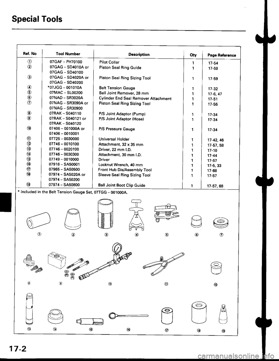
Ref. No I Tool NumberDescriptionOty I Pag€ Reterence
o
@
@
@
@
fof
@
@
@
@
@
@
@
@
@
@
@
@
@
07GAF - PH70100
07GAG - SD4010A or
07GAG - SD40100
07GAG - SD4020A or
07GAG - S040200*07JGG - 00r 010A
07MAC - 5100200
OTNAD - SR3O2OA
07NAG - SR3090A or
07NAG - SR30900
07RAK - 5040110
07RAK - 5040121 or
07RAK - 5040t20
07406 - 0010004 or
07406 - 001000r
07725 - 0030000
07746 - 0010100
07746 - 0020100
07746 - 0030300
07749 - 0010000
07916 - SA50001
07965 - SA50500
07974 - SA5020A or
07974 - SA50200
07974 - SA50800
Pilot Collar
Piston Seal Ring Guide
Piston Seal Ring Sizing Tool
Belt Tension Gauge
Ball Joint Remover, 28 mm
Cylinder End Seal Bemover Attachment
Piston Seal Ring Sizing Tool
P/S Joint Adaptor (Pump)
P/S Joint Adaptor (Hose)
P/S Pressure Gauge
Universal Holder
Attachment,32 x 35 mm
Driver, 22 mm l.D.
Attachment, 30 mm l.D.
Driver
Locknut Wrench, 40 mm
Front Hub DiVAssembly Tool
Sleeve Seal Ring Sizing Tool
Bsll Joint Boot Clip Guide
1
1
'I
1'I
1
I
1
1
I
1
1
I
1
1
I
1
I
11-54
17-59
'17-59
17 -32
17 -6, 47
17-51
| /-ao
17 -34
17 -31
't7 -34
't7-42, 16
17-57,58
17-10
17-44't7 -57
17-5,33
17-68
17 -57
17-57, 6A* lncluded in the Belt Tension cauge Set, 07TGG - OO10OOA.
o
p
v
@o
€_
ts7-dysB
aal
@@
(o)
F=1
@@@
@@@
17-2
Page 1077 of 2189
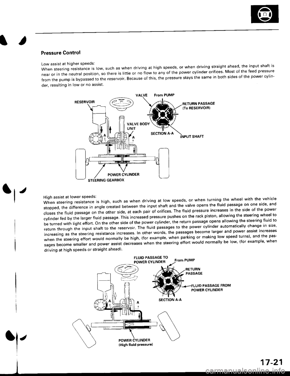
Pressure Control
Low assist at higher speeds:
WhensteeringresistanceIsIow,suchaswhendrivingathighspeeds,orwhendrivingstraightahead,theinputshaftis
near or in the neutral position, so there is little or no fiow ro any of the power cylinder orifices. Most oI the feed pressure
fromthepumpisbypassedtothereservoir.Becauseofthis,thepressurestaysthesameinbothsidesofthepowercy||n-
der, resulting in low or no asslst
VALVE From PUMP
SECTION A-A
RETURN PASSAGElTo RESERVOIRI
POWER CYLINDER
STEERING GEARBOX
High assist at lower speeds:
When steering resistance is high. such as when driving at low speeds' or when turning the wheel wirh the vehicle
stopped,thedifference|nang|ecreatedbetweentheinputshaftandtheVa|veopensthef|uidpassageononeside,and
c|osesthefluidpassageontheotherside,ateachpairoforifices'Thef|uidpressureincreasesinthesideo|thepower
cy|inder|edbythe|argerf|uidpassage'Thisincreasedpressurepushesontherackpiston,a|lowingthesteeringwhee|to
be turned with light effort. on the other side of the power cylinder, the return passage opens allowing the steering tluid to
returnthroUghtheinputshafttothereservoir'Thef|uidpassagestothepowercy|inderautomatica||ychangeins|ze,
increasing as the steering resrstance increases. In other words, the passages become larger and power assist increases
when the steering effort would normally be high, (for example' when parking or making low speed turns)' and the pas-
sagesbecomesma||erandpowerassistdecreaseswhenthesteeringeffortwou|dnorma||ybe|ow,(forexamp|e,when
driving at high speeds or straight ahead).
FLUIO PASSAGE TO
POWER CYLINDER
/t=\\a!-4,))
=YjJ
RESERVOIR
SECTION A-A
l'
{High fluid Pressure}
Page 1108 of 2189
Steering Gearbox
Disassembly (cont'dl
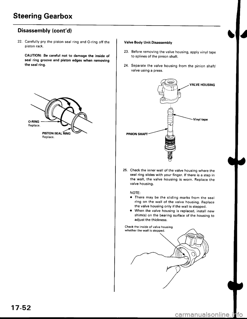
22. Carelully pry the piston seal ring and O-ring off theprslon rack.
CAUTION| Be caletul not to damage the inside ofseal ring groove and piston edges when removing
the seal rin9,
Replace.
17-52
Valve Body Unii Disassembly
23. Eefore removing the valve housing, apply vinyl tapeto splines of the pinion shaft.
24. Separate the valve housing from the pinion shaft/
valve using a press.
VALVE HOUSING
Vinylt.pe
PINION SHAFT
Check the inner wall of the valve housing where theseal ring slides with your finger. lf there is a step inthe wall, the valve housing is worn. Replace thevalve housing.
NOTE:
There may be the sliding marks from the sealring on the wall of the valve housing. Replace
the valve housing only if the wall is stepped.When the valve housing is replaced, jnstall new
shim(s) on the bearing surface of the housing toadjust the thickness.
Check the inside of valve housingwhether the wall is stepped.
Page 1112 of 2189
Steering Gearbox
Reassembly (cont'd)
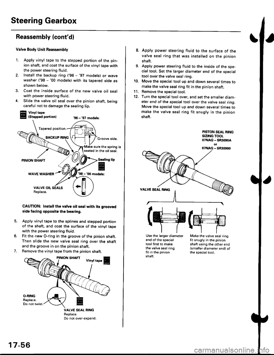
Valve Body Unit Reassembly
1. Apply vinyl tape to the stepped portion of the pin-
ion shaft, and coat the surface of the vinyl taoe with
the power steering fluid.
2. Install the backup ring ('96 -'97 models) or wavewasher ('98 -'00 models) with its tapered side as
shown below.
3. Coat the inside surface of the new valve oil sealwith power steering fluid.
4. Slide the valve oil seal over the pinion shaft, being
careful not to damage the sealing lip.
Vinyl t.po{Stepped ponion}
Tap6red position.
BACKUPGroove side.
sure the spring isseatod in the oil seal.
'98 - '00 mod.b:
CAUTION: InstEll ihe valve oil seal whh its groov.d
3ide tacing opposite tho boaring.
Apply vinyl tape to the splines and stepped portion
of the shaft, and coat the surface of the vinyl tapewith the power steering fluid.
Fit the new O-ring in the groove of the pinion shaft.Then slide the new valve seal ring over the shaft
and the groove in on the pinion shaft.
Remove the vinyl tape from the pinion shaft,
'96 - '97 models:
lip
7.
VALVE SEAL RIiIGReplace.Do not over-expand.
17-56
8. Apply power steering fluid to the surface of the
valve seal ring that was installed on the pinion
shaft.
9. Apply power steering fluid to the inside of the spe-cial tool. Set the larger diameter end of the specialtool over the valve seal ring.
10. Move the special tool up and down several times tomake the valve seal ring fit in the pinion shaft.11, Remove the soecial tool.
12. Turn the special tool over, and set the smaller diam-eter end of the special tool over the valve seal ring.Move the special tool up and down several times tomake the valve seal ring fit snugly in the pinion
shaft.
PISTON SEAL BINGSIZING TOOL07NAG - SR:togoAol07NAG - SR3|X)00
(g(m
Use the larger diameterend of the specialtool first to makethe valve seal ringfit in the pinionshaft.
Make the valve seal ringfit snugly in the pinionshaft using the other end(smaller diameter end) ofthe specialtool.
Page 1115 of 2189
)
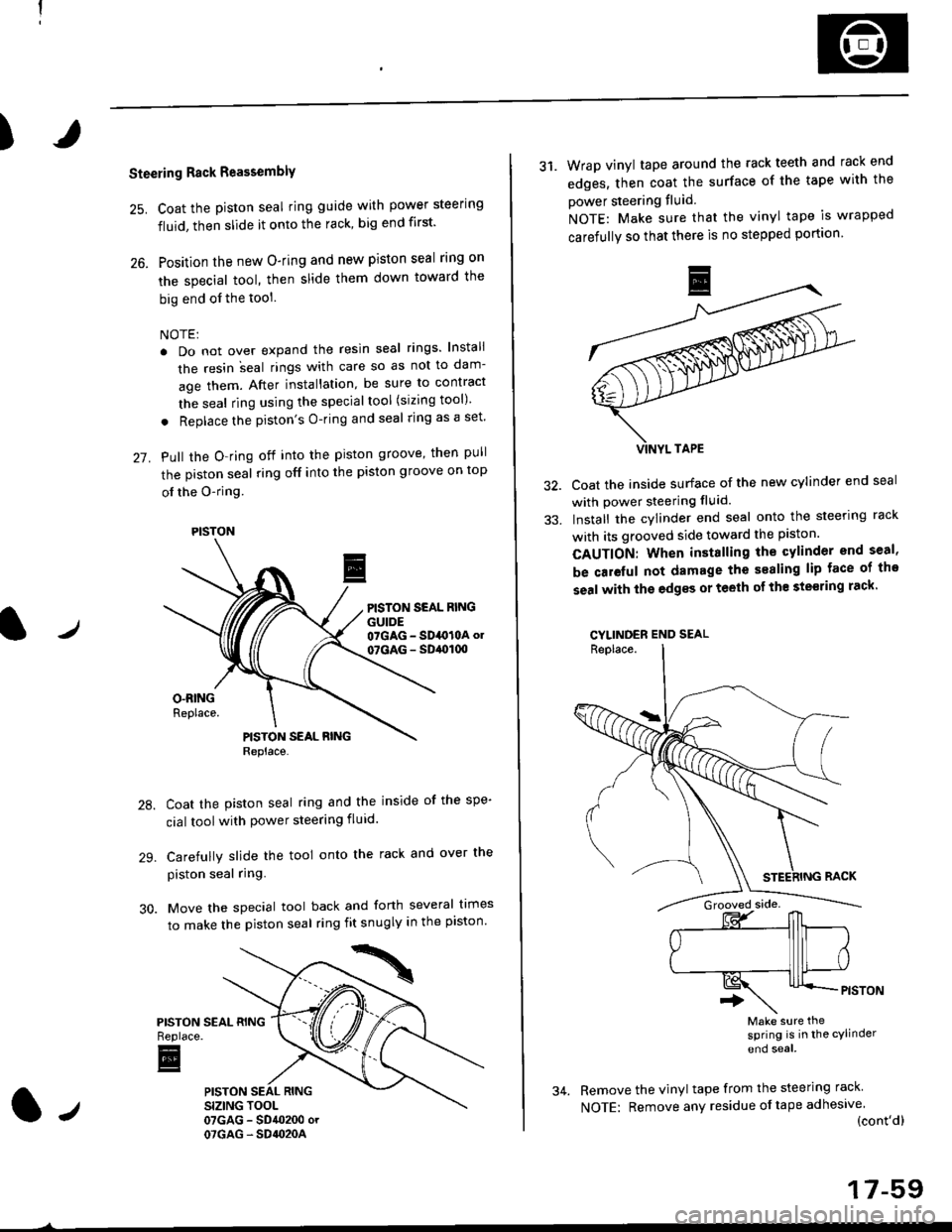
Steering Rack Reassembly
25. Coat the piston seal ring guide with power steering
fluid, then slide it onto the rack, big end first'
26. Position the new O-ring and new piston seal rlng on
the special tool, then slide them down toward the
big end of the tool
NOTE:
. Do not over expand the resin seal rings lnstali
the resin ;eal rings with care so as not to dam-
age them. After installation, be sure to contract
the seal ring using the specialtool (sizing tool)
. Replace the piston's O-ring and seal ring as a set'
27. Pull the O-ring off into the piston groove, then pull
the piston seal ring off into the piston groove on top
ol the O-ring
PISTON SEAL RINGGUIDE07GAG - SD4O10A ol
07GAG - SD,ol(xt
Coat the piston seal ring and the inside of the spe-
cial toolwith power steering fluid.
Carefully slide the tool onto the rack and over the
piston seal ring.
Move the special tool back and forth several times
to make the piston seal ring fit snugly in the piston'
PISTONReplace.
E
PISTON
31. Wrap vinyl tape around the rack teeth and rack end
edges, then coat the surface of the tape with the
power steering fluid
NOTE: Make sure that the vinyl tape is wrapped
carefully so that there is no stepped portion
Coat the inside surface of the new cylinder end seal
with power steering fluid.
Install the cylinder end seal onto the steering rack
with its grooved side toward the piston.
CAUTION: When installing the cylinder end seal,
be caieful not damage the sealing lip face of tho
seal with the edgss or teeth of th€ ste€ring rack'
CYLINDER END SEAL
Make sure thesPring is in the cylinder
end soal
Remove the vinyl tape from the steering rack
NOTE: Remove any residue oftape adhesive(cont'dl
17-59
Page 1116 of 2189
Steering Gearbox
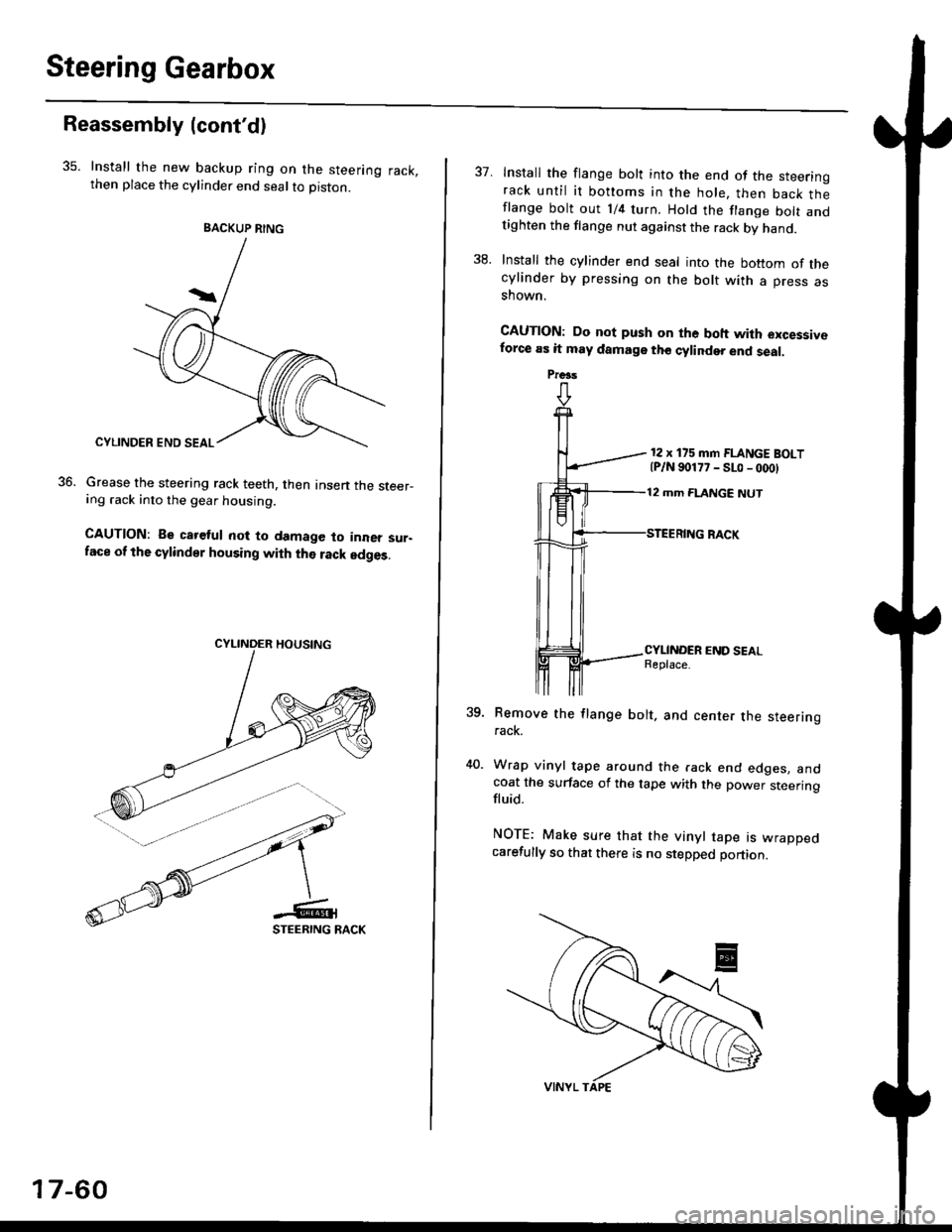
Reassembly {cont'd)
35. Install the new backup ring on the steering rack,then place the cylinder end seal to piston.
Grease the steering rack teeth, then Insen the steer-ing .ack into the gear housing.
CAUTION: Be careful not to damage to inner sur-face of the cylindsr housing with the rack edges.
36.
BACKUP RING
17-60
37. Install the flange bolt into the end of the steerinorack until it bottoms in the hole, then back thlflange bolt out 1/4 turn. Hold the flange bolt andtighten the flange nut against the rack by hand.
38. Install the cylinder end seal into the bottom of thecylinder by pressing on the bolt with a press asshown.
CAUTION: Do not push on the boh with excessiveforce as it may damage tho cylinder end seal.
12 x 175 mm FLANGE BOLT{P/N 90177 - SLo - 000}
12 mm FLANGE NUT
?qRemove the flange bolt. and center the steeringrack.
Wrap vinyl tape around the rack end edges. andcoat the surface of the tape with the power steeringfluid.
NOTE: Make sure that the vinyl tape rs wrappedcarefully so that there is no stepped portion.
Preas
Page 1117 of 2189
)
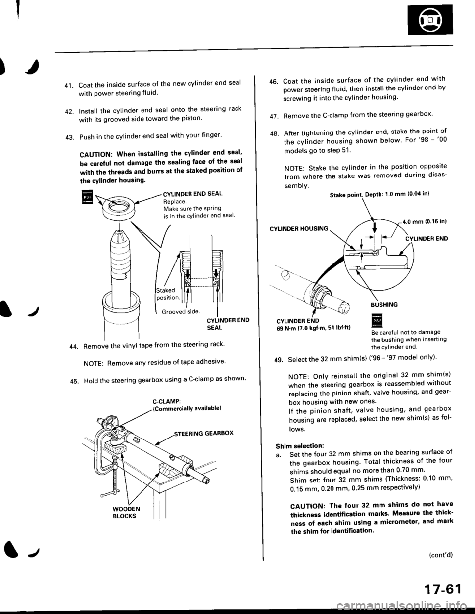
41.Coat the inside surface of the new cylinder end seal
with power steering fluid.
Install the cylinder end seal onto the steering rack
with its grooved side toward the piston'
Push in the cylinder end seal with your finger'
CAUTION: When installing the cylinder end sesl'
be carelul not damage the sealing face ot the seal
with the threads and burrs at the staked position oI
the cylinder housing.
trCYLINDES END SEAL
Replace.Make sure the sPring
is in the cylincler end seal
CYLINDER END
SEAL
Remove the vinyl tape from the steering rack'
NOTE: Remove any residue oftape adhesive
Hold the steering gearbox using a C-clamp as shown'
GEARBOX
C-CLAMP:
l-,
46.
47.
Coat the inside surface of the cylinder end with
power steering fluid, then installthe cylinder end by
screwing it into the cylinder housang.
Remove the C-clamp from the steering gearbox'
After tightening the cylinder end' stake the point of
the cylinder housing shown below For'98 -'00
models go to step 51.
NOTE: Stake the cylinder in the position opposite
from where the stake was removed during disas-
semoly.
Be careful not to damage
the bushing when inserting
the cylinder end.
49. Select the 32 mm shim(s) ('96 -'97 model only)'
NOTE: Only reinstall the original 32 mm shim(s)
when the steering gearbox is reassembled without
replacing the pinion shatt, valve housing, and gear
box housing with new ones.
lf the pinion shaft, valve housing, and gearbox
housing are replaced, select the new shim{s) as fol-
lows.
Shim selection:
a. Set the four 32 mm shims on the bearing surface of
the gearbox housing. Total thickness of the four
shims should equal no more than 0 70 mm'
Shim set: four 32 mm shims (Thickness: 010 mm'
0.15 mm, 0.20 mm, 0.25 mm respectivelyl
CAUTION: Th€ four 32 mm shims do not have
thickness identification marks Measure the thick-
ness of each shim using a micrometsr, and mark
the shim lor identification.
(cont'd)
17-61
Stake point. Depth: 1 0 mm (0.04 in)
Page 1158 of 2189
Inspection and Adjustment
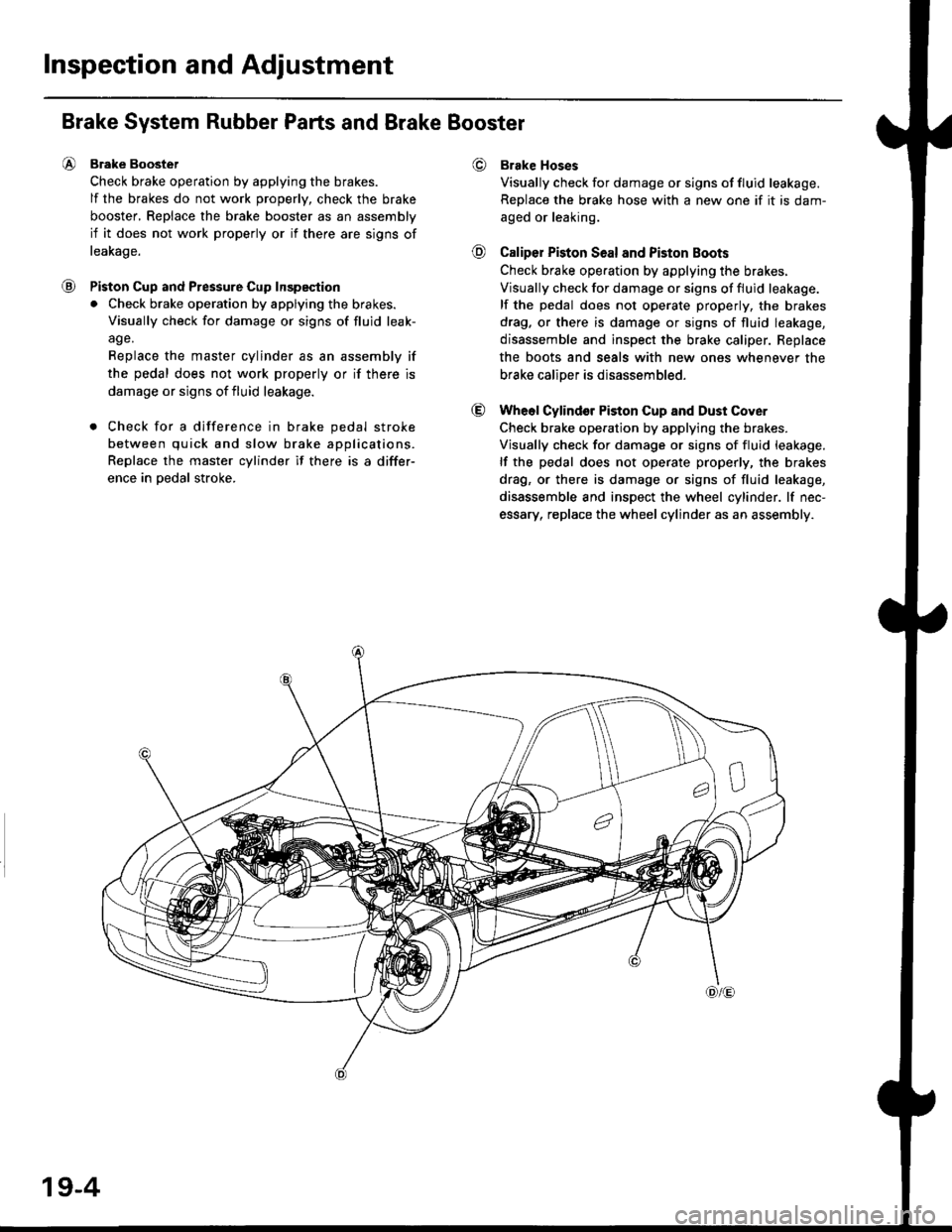
€)
@
@
@
Brake System Rubber Parts and Brake Booster
Brake Boostet
Check brake operation by applying the brakes.
lf the brakes do not work properly, check the brake
booster, Replace the brake booster as an assembly
if it does not work properly or if there are signs of
leakage.
Piston Cup and Pressure Cup Inspeqtion
. Check brake operation by applying the brakes.
Visually check for damage or signs of fluid leak-
age.
Replace the master cylinder as an assembly if
the pedal does not work properly or if there is
damage or signs of fluid leakage.
. Check for a difference in brake pedal stroke
between quick and slow brake applications.
Replace the master cylinder if there is a differ-
ence in oedal stroke.
Brake Hoses
Visually check for damage or signs of fluid leakage.
Replace the brake hose with a new one if it is dam-
aged or leaking.
Caliper Piston Seal and Piston Boots
Check brake ope.ation by applying the brakes.
Visually check for damage or signs of fluid leakage.
lf the pedal does not operate properly, the brakes
drag. or there is damage or signs of fluid leakage,
disassemble and inspect the brake caliper. Replace
the boots and seals with new ones whenever the
brake caliDer is disassembled.
Wheol Cylindor Piston Cup and Dust Cover
Check brake operation by applying the brakes.
Visually check for damage or signs of fluid leakage.
lf the pedal does not operate properly, the brakes
drag, or there is damage or signs of fluid leakage,
disassemble and inspect the wheel cylinder. lf nec-
essary, replace the wheel cylinder as an assembly.
19-4
Page 1163 of 2189
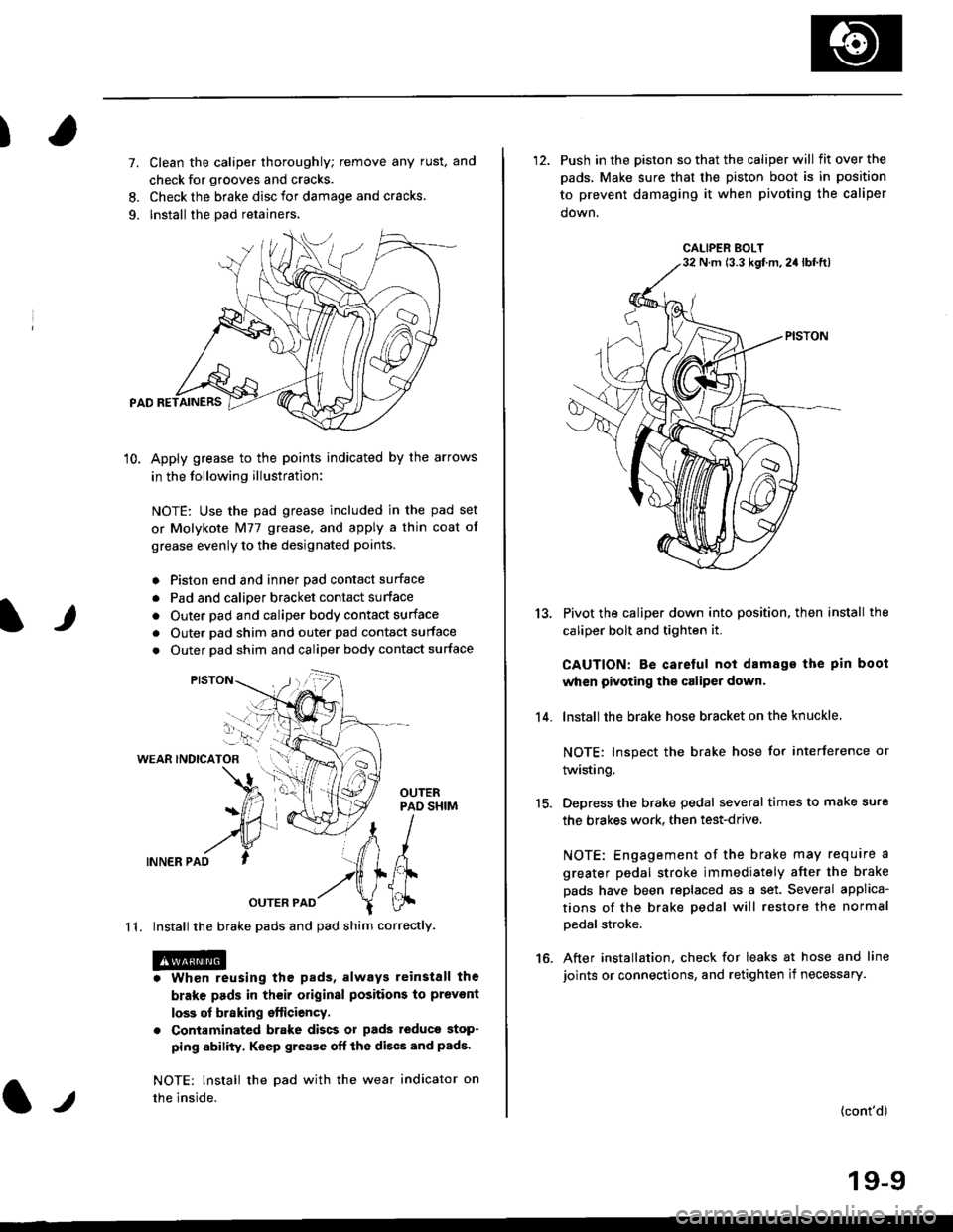
)
It
7. Clean the caliper thoroughly; remove any rust, and
check for grooves and cracks.
8. Check the brake disc for damage and cracks.
9. lnstall the pad retainers,
10. Apply grease to the points indicated by the arrows
in the following illustration:
NOTE: Use the pad grease included in the pad set
or Molykote Nl77 grease, and apply a thin coat of
grease evenly to the designated points.
o Piston end and inner Dad contact surface
. Pad and calioer bracket contact surface
. Outer pad and caliper body contact surface
. Outer pad shim and outer pad contact surface
. Outer pad shim and caliper body contact surface
WEAR INDICATOB
INNER PAD
OUTER PAD
1 1. Install the brake pads and pad shim correctly.
. Whon reusing the pads, always reinstall the
brake pads in their original positions to prevont
loss of braking efticiency.
. Contaminated brake discs or pads teduce stop-
ping ability. Keep grease oft the discs and pads'
NOTE: lnstall the Dad with the wear indicator on
the inside.l.t
'12. Push in the piston so that the caliper will fitoverthe
pads, Make sure that the piston boot is in position
to prevent damaging it when pivoting the caliper
down.
Pivot the caliper down into position, then install the
caliper bolt and tighten it.
CAUTION: Be caretul not damage the pin boot
when pivoting the caliper dowr.
lnstall the brake hose bracket on the knuckle
NOTE: Inspect the brake hose for interference or
twisting.
Depress the brake pedal several times to make sure
the brakes work. then test-drive.
NOTE: Engagement of the brake may require a
greater pedal stroke immediately after the brake
pads have been replaced as a set. Several applica-
tions of the brake pedal will restore the normal
Dedal stroke.
After installation. check for leaks at hose and line
joints or connections, and retighten if necessary.
13.
14.
15.
16.
(cont'd)
19-9
CALIPER BOLTN m (3.3 kgf m,2a lbf.ft)
Page 1165 of 2189
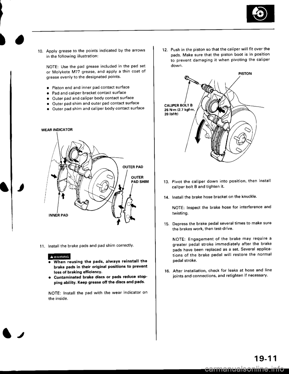
)
lO. Apply grease to the points indicated by the arrows
in the following illustration:
NOTE: Use the pad grease included in the pad set
or Molykote M77 grease, and apply a thin coat of
grease evenly to the designated points.
. Piston end and inner pad contact surface
o Pad and caliper bracket contact surface
. Outer pad and caliper body contact surface
. Outer pad shim and outer pad contact surface
. Outer pad shim and caliper body contact surface
OUTER PAD
OUIERPAD SHIM
I 1. Install the brake pads and pad shim correctly
@o When reusing the pads, always reinstall the
brake pads in their original positions to plevent
loss of braking etticiencY.
. Contaminated brake discs ol pads reduce stop-
ping ability. Keep grease oft the discs and pads.
NOTE: Install the pad with the wear indicator on
the inside.
WEAR INDICATOR
12. Push in the piston so that the caliper will fit over the
pads. Make sure that the piston boot is in position
to prevent damaging it when pivoting the caliper
CALIPER BOLT B26 N.m {2.7 kgt m,
20 rbl.ftl
14.
13.Pivot the caliper down into position, then install
caliper bolt B and tighten it.
lnstallthe brake hose bracket on the knuckle.
NOTE: Inspect the brake hose for interference and
twisting.
Depress the brake pedal several times to make sure
the brakes work, then test-drive
NOTE: Engagement of the brake may require a
greater pedal stroke immediately after the brake
pads have been replaced as a set. Several applica-
tions ot the brake pedal will restore the normal
pedal stroke.
After installation, check for leaks at hose and line
joints and connections, and retighten if necessary.16.
PISTON
19-1 1