relay HONDA CIVIC 1998 6.G Repair Manual
[x] Cancel search | Manufacturer: HONDA, Model Year: 1998, Model line: CIVIC, Model: HONDA CIVIC 1998 6.GPages: 2189, PDF Size: 69.39 MB
Page 1213 of 2189
Troubleshooting
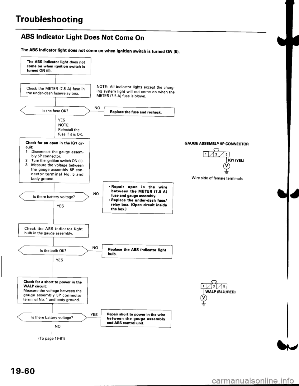
ABS Indicator Light Does Not Come On
YES
NOTE:Reinstallthefuse if it is OK.
The A8S indicator light does not come on when ignition switch is turned ON ll.
NOTE: All indicator tights except the charg,ing system light will not come on when theMETER 17.5 A) ft se is btown.
NO
GAUGE ASSEMBI"Y 5P CONNECTOR
Wire side of female terminals
Tho ABS indicator light does notcome on wh€n ignition switch istu.ned ON {lll.
check the METEB (7.5 A) fuse inthe under-dash fuse/relay box.
Beplace the tu3e and recheck.
Check for an open in th6 lcl cir-cuii:1, Disconnect the gauge assembly 5P connector.2. Turn the ignitjon switch ON l).3. Measure the voltage betweenthe gauge assembly 5P con-nector terminal No. 5 andbody ground.
. Ropair opan in tho wirobotwe€n thc METER t7.5 Attuso and gauge .$cmbly.. Roplacc th. und.r-dash tus./r.l.y box. lop.r cirouit in3idothe box.l
ls there baftery voltage?
Check the ABS indicator lightbulb in the gauge assembly.
ls the bulb OK?
Ch€ck tor a short to power in theWALP circuit:Measure the voltage between thegauge assembly 5P connectorterminal No. I and body ground.
Replir short to power in tho wiiGb.tweon the gruge rs3embly.nd ABS control unh.
ls there battery voltage?
lTo page 19-61)
19-60
Page 1215 of 2189
Troubleshooting
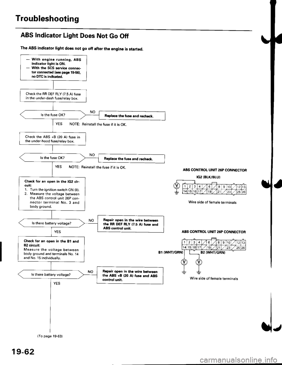
The ABS indicator light does not go off after the engine is started.
- With engine running, ABSindicator light is ON.- With tho SCS sewice connec-to. connected l3oe page 19-561,no DTC is indicated,
Checkthe RR DEF RLY {7.5 A)tusein the under-dash fuse/relay box.
Raphco tha furo and rochack.
Check the ABS +B (20 A) fuse inthe under hood tuse/relay box.
R6pl.ce tho tu3c lnd r.ch.ck.
Chock for an open in the lG2 cir-GUrt:1. Turn the ignition switch ON (lt).2. Measure the voltage betweenthe ABS control unh 26P con-nector terminal No. 3 andbody ground.
Bopair opcn in tha wir. botw.cnth. RR DEF RLY 17.5 Al tus. .ndABS control unit.
Check tor an opon in thG Bl end82 circuit:Measure the voltage betweenbody ground and terminals No. 14and No. 15 individually.
Rrpair opsn in tha wiro t atwa,anthe ABS +B (20 Al fu.r .nd ABScontrol unh.
ls there banery voltage?
1To page 19-63)
ABS Indicator Light Does Not Go Off
YES NOTE: Feinstattthe luse it it is OK.
YES NOTE: Reinsta
the fuse if it is OK.ABS CONTROL UNIT 26P CONNECTOR
IG2IELK/BLUI
Wire side of female terminals
ABS CONTBOL UN]T 26P CONNECTOR
8T IWHT/GRNI
Wire side of temale terminals
19-62
Page 1221 of 2189
Troubleshooting
ABS Pump Motor
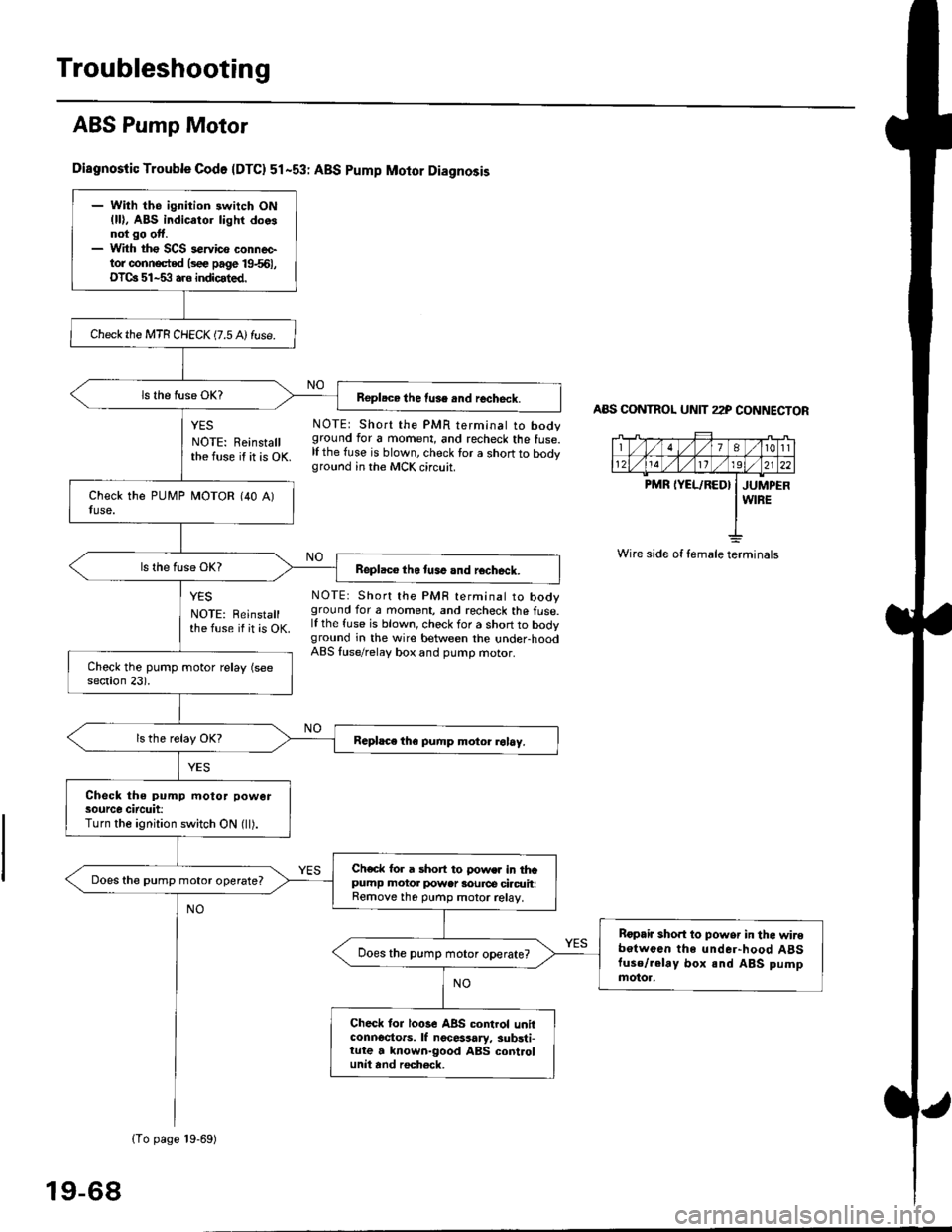
Diagnostic Trouble Codo {DTC} 51-53r ABS pump Motor Diagnosis
YES NOTE: Short the PMR terminat to body
NOTE: Reinstall ground for a moment, and recheck the fuse.
the fuse if it is OK lf the fuse is blown, check for a short to bodyground in the MCK circuit.
AAS CONTNOL UNIT 22P CONNECTOR
7At0tl
1211192l22
PMR IYEL/RED} I JUMPERI WIRE
Wire side of female terminals
NO
NO
YES
NOTE: Reinstallthe fuse if it is OK.
NOTE: Short the PMF terminal to booyground for a moment, and recheck the fuse.lf the fuse is blown, check for a short to bodyground in the wire between the under-hoodABS luse/relaV box and pumD motor.
- With the ignition switch ON(ll), ABS indicator lighr doosnot go otf.- With tho SCS s€rvico conneetor conn€cted lsee page 19661,OTCa 51-53 aro indicated.
Check the MTR CHECK (7.5 A) fuse.
Repl.ce the fuse .nd recheck.
Replaco tho tuse and rocheck.
Rcphce th€ pump motor rol6y.
Check the pump motor powersource circuit:Turn the ignition switch ON (ll).
Ch€ck for a short to !'ows. in thopumP motor power 3ource ciacrrit:Remove th6 purnp motor relay,
Does the pump motor operate?
Bopair sho.t to powsr in the wir€botwoen the under-hood A8Stuse/.elay box and ABS pumpmotor.
Does the pump motor operate?
Check tor loGe ABS control unitconnoctors. lf nocessary, substi-tute a known-good ABS controlunit and roch€ck,
(To page 19-69)
19-68
Page 1222 of 2189
tt
(From page 19-68)UNDER.HOOD ABSFUSE/RELAY 8()X
TERMINAL TERMINAL
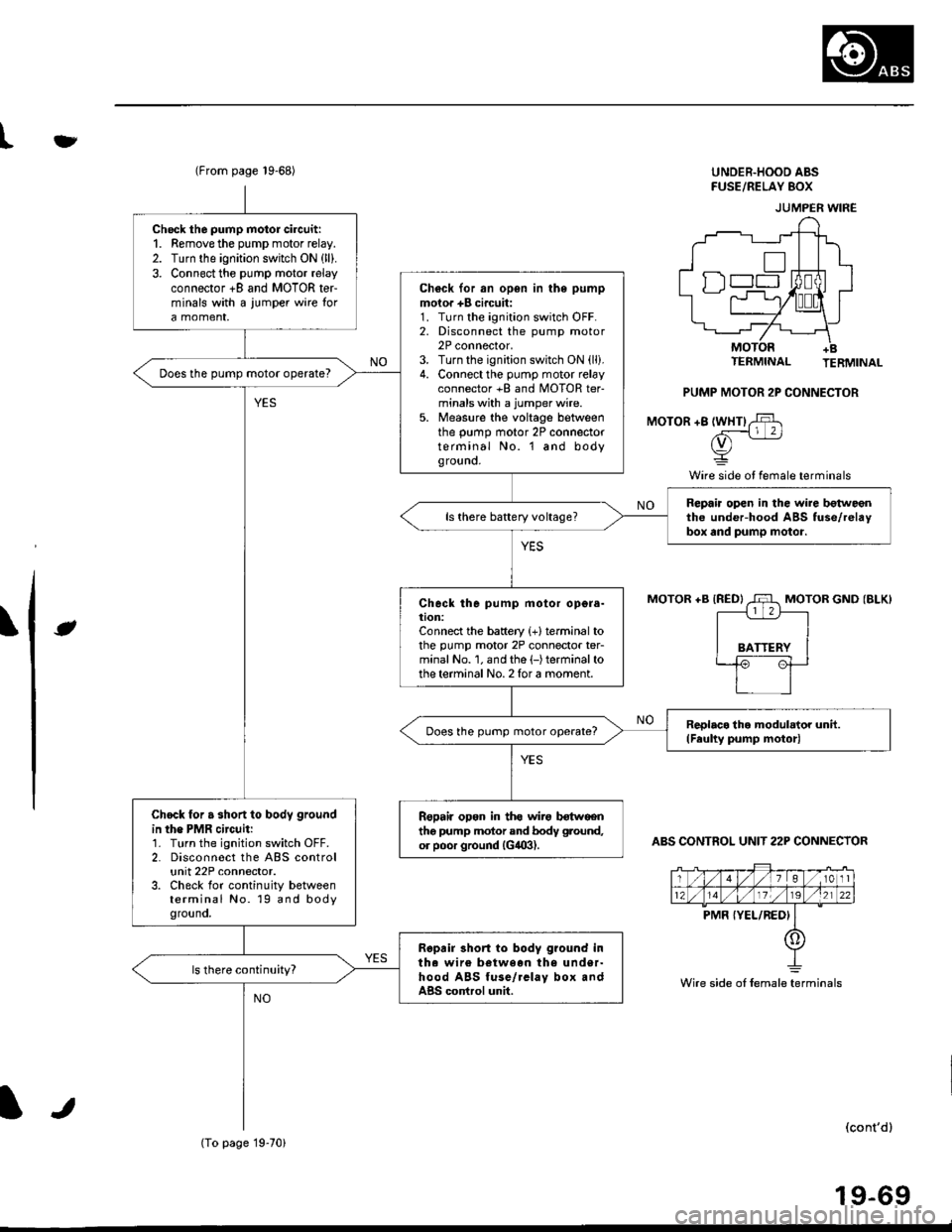
PUMP MOTOR 2P CONNECTOR
MOTOR +8 lWHTl,$
rv) -
Y
Wire side ot female terminals
\lt
MOTOR +B {RED}MOTOR GND (BLK)
ABS CONTROL UNIT 22P CONNECTOR
(cont'dl
19-69
JUMPER WIRE
Wire side oI female terminals
Check the pump motor circuit:1. Remove the pump motor relay.2. Turn the ignition switch ON (ll).
3. Connect the pump motor relayconnector +8 and MOTOR terminals with a iumper wire tora momenr,
Ch€ck for an open in the pump
moior +B circuit:1. Turn the ignition switch OFF.2. Disconnect the pump motor2P connector,3. Turn the ignition switch ON (ll).
4. Connect the pump motor relayconnector +B and MOTOR ter-minals with a jumper wire.5. Measure the voltage betweenthe pump motor 2P connectorterminal No. l and bodyground.
Does the pump motor operate?
Repaia open in the wire botweentho under-hood ABS fuse/relaybox and pump motor.ls there battery voltage?
Check the pump motor opgra-tion:Connect the battery {+}terminal tothe pump motor 2P connector ter-minal No. 1. and the (-)terminalto
the terminal No. 2 for a moment.
ReDlaco lho modulator unit.(Feulty pump motor)Does the pump motor operate?
Chock for a short to body ground
in the PMR circuit:1. Turn the ignition switch OFF.2. Disconnect the ABS controlunit 22P connector.3. Check for continuity betweenterminal No. 19 and bodygrouno,
Repail opon in ths wirg botwgentho pump motor and bodv ground,
or poor ground (G,!09).
Ropair 3hort to body g?ound intha wire between the under-hood ABS fuse/rclay box andABS cortrol unit.
(To page 19-70)
Page 1223 of 2189
Troubleshooting
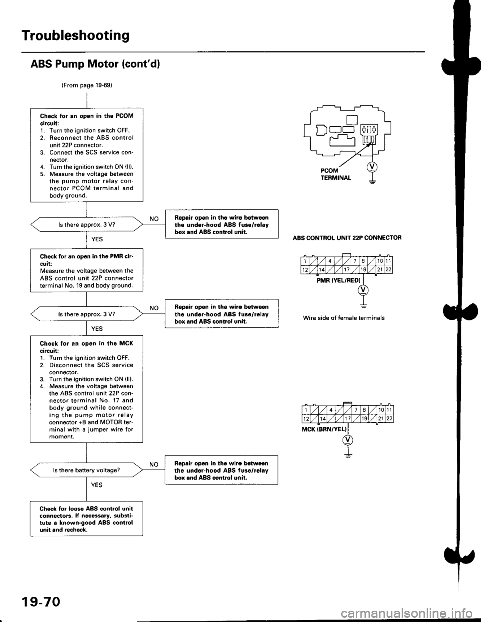
ABS Pump Motor (cont'dl
(From page 19-69)
ABS CONTROL UNIT 22P CONNECTOR
Check tor an opon in the PCOMcircuit:1. Turn the ignition switch OFF.2. Reconnect the ABS controlunit 22P connector.3. Connect the SCS service con-nector,4. Turn the ignition switch ON (ll).
5. Measure the voltage betweenthe pump motor relay connector PCOI,I terminal andbody ground.
Repair opon in tha wiro bEtwoonth. und€r-hood ABS fu3./rclsybox and ABS control unit.ls there approx. 3 V?
Chock for rn op6n in tho PMR cir-cuit:Measure the voltage beNveen theABS control unit 22P connectorterminal No. 19 and body ground.
Ropair opon in tho wira b€twoontho undor-hood ABS fu.e/rel.ybox and ABS control unit.ls there approx. 3 V?
Chock for an opon in ths MCKcircuh:1. Turn the ignition switch OFF.2- Disconnect the SCS serviceconnector.3. Turn the ignition switch ON lll).4. Measure the voltage betweenthe ABS control unit 22P con-nector terminal No. 17 andbody ground while connect-ing the pump motor relayconnector +8 and MOTOR ter'minal with a jumper wire formoment.
Repeir op.n in th. wire batweentho undor-hood ABS fu.o/rol.Vbox rnd ABS control unh.
Ch6ck lor loose ABS contlol unitconnoctors. lf ngc63ary, sub3ti-tute d known-good ABS controlunit and recheck.
n--l
wire side oI temale terminals
19-70
Page 1224 of 2189
tfMain Relay
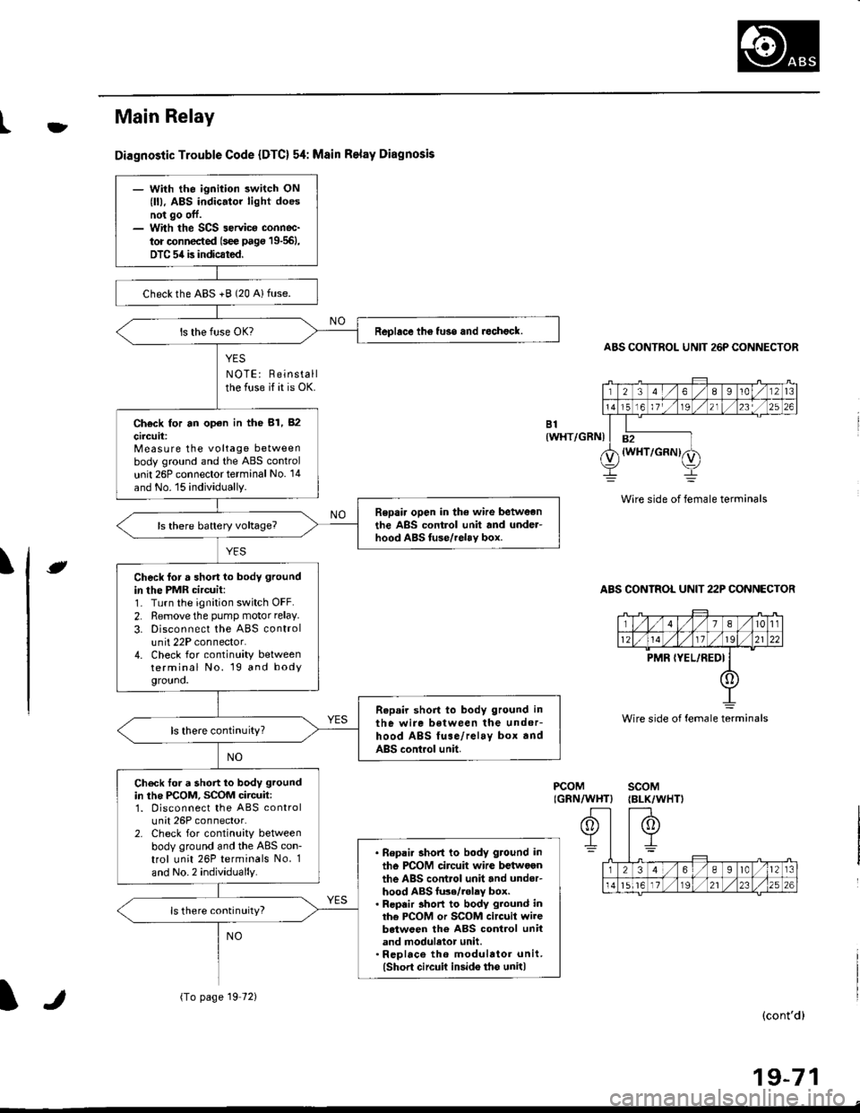
Diagnostic Trouble Code {DTC} 54: Msin Relay Diagnosis
YES
NOTE: Reinstallthe fuse if it is OK.
ABS CONTROL UNIT 26P CONNECTOR
Wire side of female terminals
ABS CONTROL UNIT 22P CONNECTOR
B1{WHT/GRNI
\e
PCOMIGRN/WHT}scoM{BLK/WHTI
(cont'd)
19-71
Wire side of female terminals
- With the ignition switch ON
{ll), ABS indic.tor light doesnot go off.- With the SCS 3ervica connoc-
tor connected (s€e pag€ 19-561,
DTC 54 is indicated.
checkthe ABS +B (20 Alfuse.
Replace th6 fuso and rechock.
Ch€ck for an op€n in the 81, 82
circuit:Measure the voltage betweenbody ground and the ABS control
unit 26P connector terminal No. '14
and No. 15 individually.
Repair open in the wire betweonthe ABS control unit and under-hood ABS tuse/relav box.
Check for a short lo body ground
in the PMR circuit:1- Turn the ignition switch OFF.
2. Remove the pump motor relay.
3. Disconnect the ABS controlunit 22P connector.4. Check for continuity betweenterminal No. 19 and bodygrouno.
Repair short to body ground in
the wire between the undor-hood ABS fuse/relay box andABS control unit.
ls there continuity?
Check tor a short to body ground
in the PCOM, SCOM circuit:1. Disconnect the ABS controlunit 26P connector.2. Check for continuity betweenbody ground and the ABS con-trol unit 26P terminals No. 1
and No.2 individually.
. Bepai. short to body ground in
tho PCOM circuit wire betwoenthe ABS control unit and under-hood ABS fu3e/.olay box.. Repair 3hort to body ground inthe PCOM or SCOM circuit wirebetween the ABS control unitand moduletor unit.. Rcplace th6 modulator unit.(Short circuit insido tho unit)
ls there continuity?
{To page 19 72)lr
Page 1225 of 2189
Troubleshooting
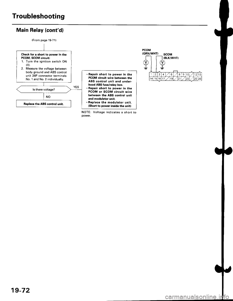
Main Relay (cont'd)
(From page 19'71)
PCOM(GRN/WHTIscoM(BLK/WHT}Check tor a short to powor in thePCOM, SCOM circuit:1. Turn the ignition switch ON r).2. Measure the voltage betweenbody ground and ABS controlunit 26P connector terminalsNo. l and No.2 individually.
. Repair 3hoit to power in ihercOM circuil wire bgtween theABS control unit end unde.-hood ABS fuse/relay box.. Repair sho to powor in thaPCOM oJ SCOM circuit wirobetwoen the ABS control unitand modulator unit.' Repl.co the modul.tor unit.lshort to Dowcr iGido the unit)Replace the ABS control unit.
Vo lta ge
19-72
Page 1281 of 2189
Troubleshooting
SymptomProbable Cause
Water leaks1. Clogged drain tube.
2. Gap between glass weatherstrjp and roof panel.
3. Defective or improperly installed glass weatherstrip.
4. Gap between drain seal and roof panel.
Wind noise'1. Excessive clearance between glass weatherstrip and roof panel.
Motor noise1. Loose motor.
2. Worn gear or bearing.
3. Cable assembly deformed.
Glass does not move, but motor turns'1. Clutch out of adjustment.
2. Foreign matter stuck between guide rail and slider.
3. lnner cable loose.
4. Cable assembly not attached properly.
Glass does not move and motor does not turn
{glass can be moved with moonroof wrench)
1. Blown fuse,
2. Faulty switch.
3. Battery run down.
4. Defective motor.
5. Faulty relay.
D
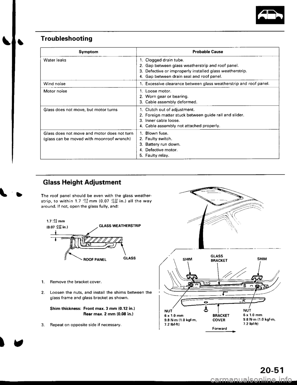
Glass Height Adjustment
The roof panel should be even with the glass weather-
strip, to within 1.7 :lr3 mm (0.07 :3:31 in.) all the way
around. lf not, open the giass fully, and:
GLASS WEATHERSTRIP
1. Remove the bracket cover.
Loosen the nuts, and install the shims between the
glass frame and glass bracket as shown.
Shim thickness: Front max.3 mm 10,12 in.l
Rear max. 2 mm 10.08 in.)
Repeat on opposite side i{ necessary.
)
5x1.0mm9.8 N.m 11.0 kgf m,7.2 rbtft)
SRACKETCOVEB
----------1>
6x1.0mm9.8 N.m {1.0 kgtm,7.2 tbf.ft)
1.7 tl.8 mm
{0.07 :3 3i in.}
20-51
Page 1300 of 2189
Dashboard
Gomponent Removal/lnstallation
(cont'd)
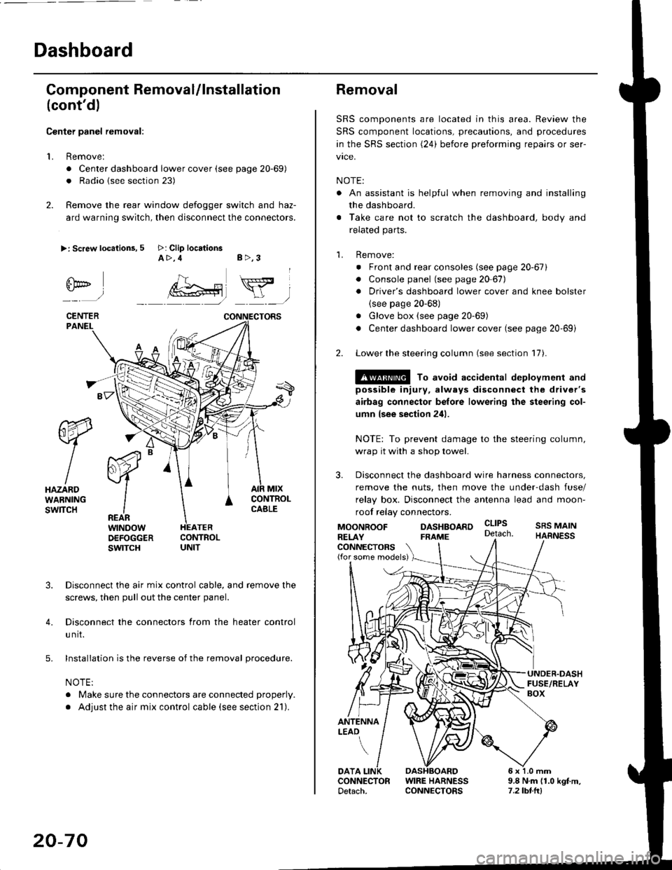
Center panel removal:
1. Remove:
. Center dashboard lower cover (see page 20-69)
. Radio {see section 23)
2. Remove the rear window defogger switch and haz-
ard warning switch, then disconnect the connectors.
>: Screw locations, 5 >: Clip locationsA>,4 B>,3
fii*-)
CENTERPANEI.
rt-xR.
W
IHAZARDWARNINGswlTcH
r44 "
F.IZvl
IIREARwtNoowOEFOGGERswtrcH
MtxCONTNOLCABLE
3. Disconnect the air mix control cable, and remove the
screws, then pull out the center panel.
4. Disconnect the connectors from the heater control
u nit.
5. Installation is the reverse of the removal procedure.
NOTE:
. Make sure the connectors are connected properly.
. Adjust the air mix control cable (see section 21).
20-70
Removal
SRS components are located in this area. Review the
SRS component locations, precautions, and procedures
in the SRS section (24) before preforming repairs or ser-
vice.
NOTE:
. An assistant is helpful when removing and installing
the dashboard.
. Take care not to scratch the dashboard, body and
related parts.
1. Remove:
o Front and rear consoles (see page 20-67)
. Console panel (see page 2O 67),
. Driver's dashboard lower cover and knee bolster(see page 20-68)
. Glove box (see page 20-69)
. Center dashboard lower cover (see page 20-69i
2. Lower the steering column (see section 17).
@ To avoid accidental deplovment and
possible injury, always disconnect the driver's
airbag connector belore lowering the steering col-
umn lsee section 241.
NOTE: To prevent damage to the steering column,
wrap it with a shop towel.
3. Disconnect the dashboard wire harness connectors,
remove the nuts, then move the under-dash fuse/
relay box. Disconnect the antenna lead and moon-
roof relay connectors.
DASHBOARD cltPs
CONNECTORS(for some models)
MOONROOFRELAY
ANTENNALEAO
FRAME
SRS MAINHARNESS
9.8 N.m (1.0 kgf m,7.2lbt.ltl
DATACONNECTOR WIRE HARNESSDetach. CONNECTORS
Page 1375 of 2189
Heater
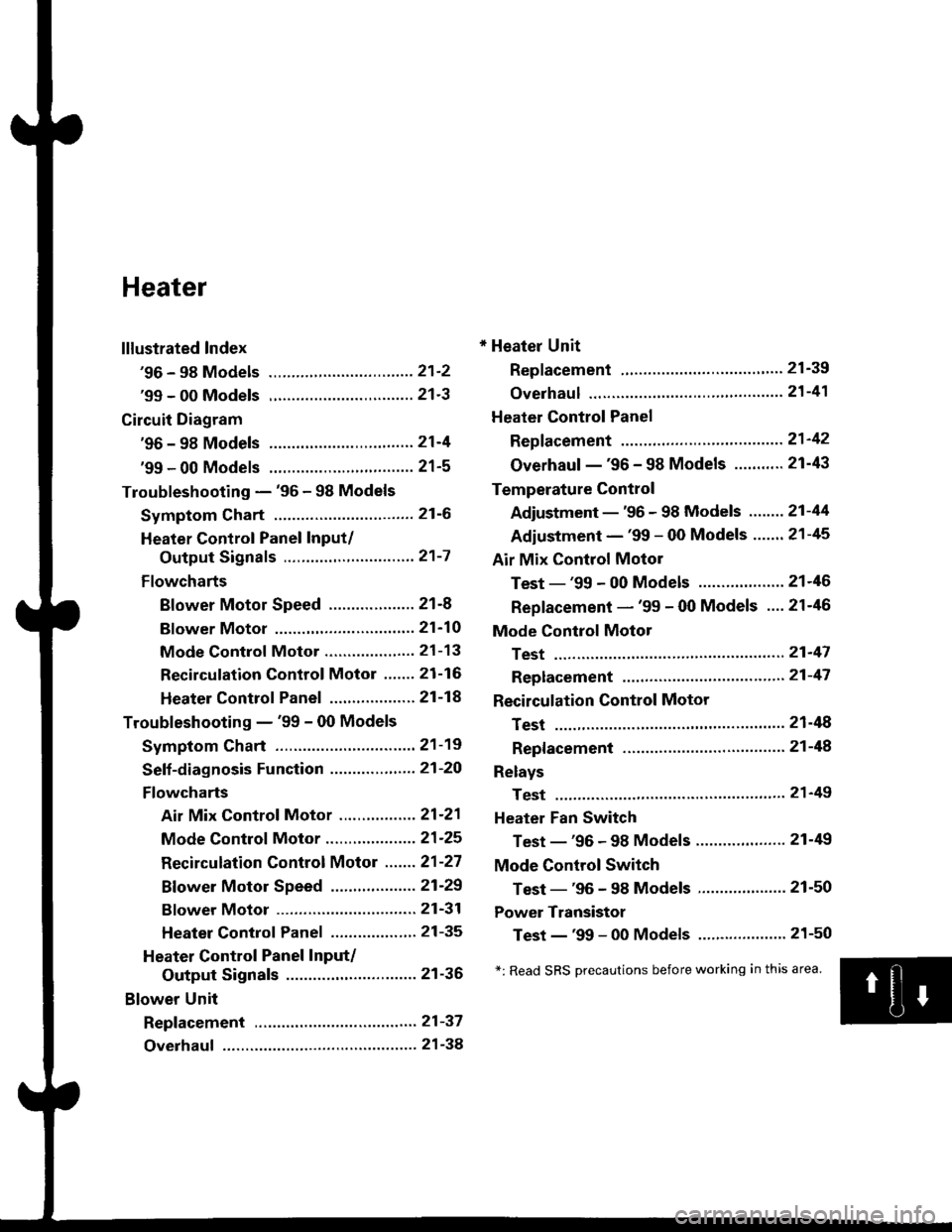
lllustrated Index
'96 - 98 Models ................................ 21'2
'99 - 00 Models ................................ 21'3
Circuit Diagram
'96 - 98 Models .....21-4
'99 - 00 Models ................................ 21-5
Troubleshooting - '96 - 98 Models
Symptom Chart ............................... 21-6
Heater Control Panel Input/
Output Signals ..............,.............. 21-7
Flowcharts
Blower Motor Speed ................... 21-8
Bf ower Motor ,...21'10
Mode Control Motor ............... ,.'.' 21-13
Recirculation control Motor ....... 21-16
Heater Control Panel ................ ... 21 -14
Troubleshooting - '99 - 00 Models
Symptom Chart ............................... 21-19
Seff-diagnosis Function ............,,,.... 21-20
Flowcharts
Air Mix Control Motor ......,.......... 21-21
Mode Control Motor ............... ..... 21 -25
Recirculation Control Motor ....... 21-27
Bf ower Motor Speed .............. .....21'29
Bf ower Motor ....21-31
Heater Control Panel ................,.. 21-35
Heater Control Panel Input/
Output Signals ............................. 21-36
Blower Unit
Repf acement .........21-37
Overhaul ................ 21-38
* Heater Unit
Replacement ....'....21-39
overhaul """" """' 21-4'l
Heater Control Panel
Repfacement .........21'42
Overhaul -'96 - 98 Models ........... 21-43
Temperature Control
Adjustment - '96 - 98 Models """" 21-44
Adiustment - '99 - 00 Models .......21-45
Air Mix Control Motor
Test - '99 - 00 Models ...........' .......21'46
Replacement - '99 - 00 Models ....21'46
Mode Control Motol
Test ................, .,...'.21'47
Replacement '.'."...21-47
Recirculation Control Motor
Test ................. .......21-48
Repf acement ......." 21-48
Relays
Test ................. .......2'l-49
Heater Fan Switch
Test - '96 - 98 Models ............. .......21-49
Mode Control Switch
Test -'96 - 98 Models ..........."....... 21-50
Power Transistor
Test - '99 - 00 Models ....'........ ....".21-50
*: Read SRS Drecautions before working in this area.