fuel flow HONDA CIVIC 1998 6.G Workshop Manual
[x] Cancel search | Manufacturer: HONDA, Model Year: 1998, Model line: CIVIC, Model: HONDA CIVIC 1998 6.GPages: 2189, PDF Size: 69.39 MB
Page 270 of 2189

!
Fuel and Emrsslons
SoecialToofs .....,...."..,. 11-2
Component Locations
lndex ....................., ......... 11-3
Svstem Description
Vacuum Connections ................,,..,.. ......... 11-12
Electrical Connections ...............,.,.,... ....... 11-29
System Connectors ........,.,.,.......................... 1 1-51
Troubleshooting
Troubleshooting Procedures ................. .. 11-81
Engine Control Module/PowertrainControl Module TerminalAfiangement ....,.,..... 11-88
Diagnostic Trouble Code Chart .................,., 11.97
How to Read Flowcharts .,.......................... . 11-103
PGM-Fl System
System Description ...... 11-10,1
Troubleshooting Flowcharts
Engine Control Module/PowertrainContlol Module ........ 11-107
Manitold Absolute Pressure Sensor .....'. . ... 11-115
fntake Air Temperatuie Sensor ..... . . ., . 11'121
Engine Coolant Temperatuae Sensol ........., 11-128
Throttle Position Sensor ...................,........... 11-132
Primary Heated Orygen Sensor (Sensor 1l ... 11-139
Secondary Heated Oxygen Sensor(Sensor 21.................................................... 1 1-153
Heated Oxygen Sensor Heater ...................,. 11-157
Fuel Supply System ...... 11-164
Random Mislire ......., ..11-166
Misfire Detected in One Cylindsr ................. 11-167
Knock Sensor .,.,............ 11-170
CKP/TDC/CYP Sensor ................................... 11'172
Vehicle Speed Sensor ...........,......,...,.,........... 1t-176
Barometric Pressure Sensor ...............,......... I 1-178
Electrical Load Detector,.,,............................ 1 1-179
CKF Sensor .................... 11-183
ECM/PCM Internal Circuit ............................. I 1-188
A/T Signal {TMA/TMBI .................................. I 1-189
ldle Control System
System Doscriplion ............ 11-190
Troubleshooting Flowcharts
ldle Control System ...... 11-192
ldle Air Control Va1ve .................................... I 1-19i1
Starter Switch Signal .................................... 1 1'202
Air Conditioning Signal ................................. 11'201
Ahernator FR Signal .................................... . 1 1-208
BrakeSwitch Signal ..................................... f 1"210
Power Sleering Prossure Switch Signal ......11-212
A/T Gear Position Signal ............................... 11-216
Clutch Swiich Signal ................................-.... 11-214
ldte Speed Setting . .............11-220
Fuel Supply System
Fuel Lines .,...................,.,.,.,11-221
Fuef Tube/Ouick-Connect Fittings ..........,.,........ 11 -227
System Description ....'.... 11-230
Fuel Pressure .......,.,,........... 11-230
Fuef fniectors ......................11-232
Fu€f Pressure Regulator .....,.......................'...,. 11-231
Fuef Fifter ............................11-235
Fuel Pump .............'.......'.... 11-236
PGM-FI Main Relay .............11'237
Fuel Tank ................ ....,...'.'.' 11'211
Intake Air System
System Description ....-.-.....11-243
Air Cfeaner ...........,......."". .11-211
Throttle Cable .....................11-211
Throttfe Body ........ ..'... . . .,.11-211
Fuel Iniestion Air Control System ,.,.,....-........... 11-250
Emission Control System
System Description .-..........11-252
Taifpip€ Emission ...............11-252
Three Way Catafytic Convert€r ............,.,,.,.,.,.... 11 -252
Exhaust Gas Racirculaiion System ...,.,,,,.,.,.,.,,. 11'254
Positive Crankcas€ Ventilation System .... . . .. 11-266
Evaoorative Emission Controls ..................,,..,.,. 11 -267
Page 353 of 2189
Troubleshooting
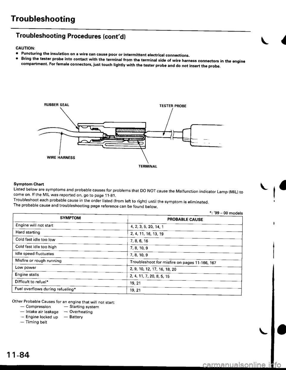
Troubleshooting Procedures (cont,dl
CAUTION:
. Punqturing ihe insulation on a wirs can cause poor or intermiftent electricar connections.I Bring the test€r probe into contacl with the terminatlrom the terminal side of wire harnesg conncctors in the gngin€compartment. For temale connectors, iust touch lightly with the tester probe and do not inse.t the probe.
\I
RUBBER SEAL
Other Probable Causes for an engine that will not start:- Compression- Starting system- lntake air leakage - Overheating- Engine locked up - Battery- Timing belt
TESTER PROBE
Symptom Chart
Listed below are symptoms and probable causes for problems that Do NoT cause the Malfunction indicator Lamp (MlL) tocome on. lfthe MIL was reported on, go to page 11_81.Troubleshoot each probabre cause in the order risted (from reft to right) untir the symptom is eriminated.The probable cause and troubleshooting page reference can be found berow.
L
*: '99 - 00 models
TERMINAL
SYMPTOMPROBABLE CAUSE
4,2,3, 5,20, 14, 1
2, 4, 11, 16, 13, 't9
?, s^6. 16
1,8,10.9
Engine will not sta rt
Hard starting
Cold fast idle too low
Cold fast idle too high
ldle speed fluctuates7,8, 10.9
Troubleshoot for misfire on pages l1-166, 167Misfire or rough running
LOW power
E"g|* "t"lb
2,9, 10, 12, 11, 16, 't8,20
2,4,11,7,20,8,5,15
't9, 21
1r, ,1
Difficult to refuel*
Fuel overflows during refueling*
11-84
Page 367 of 2189
Troubleshooting
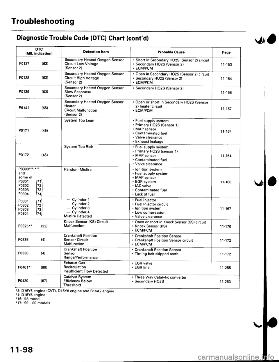
DTClMlL indicationlDatection hsmProbablo CausePage
P0137(63)Secondary Heated Oxygen SensorCircuit Low Voltage(Sensor 2)
Short in Secondary HO2S lSensor 2) circuitSecondary H02S {Sensor 2)ECM/PCI\41 1-153
P0r38 {63)Secondary Heated Oxygen SensorCircuit High Voltage(Sensor 2)
Open in Secondary HO2S (Sensor 2) circuitSecondary HO2S (Sensor 2)EC[I/PCM11-154
P0'139 (63)Secondary Heated Orygen SensorSlow Response(Sensor 2)
Secondary H02S lSensor 2)1l-156
P0141 (65)
Secondary Heated Oxygen SensorHeaterCircuit Malfunction(Sensor 2)
. Open or short in Secondary HO2S (Sensor2) heater circuit. ECM/PCM11-157
P0171 (45)
System Too LeanFuel supply systemPrimary HO2S (Sensor 1)MAP sensorContaminated fuelValve clearanceExhaust leakage
11,164
P0172 (45)
System Too RichFuel supply systemPrimary HO2S (sensor l)MAP sensorContaminated fuelValve clearance
11-164
P0300*16' }l?
andsome ofPo3o1 /r'' \P0302 l72lP0303 l73lP0304 \7 4l
Random Misfirelgnition systemFuel supply systemMAP sensorEGR systemIAC valveContaminated fuelLack of fuel
r1-r66
P0301P0302P0303P0304
/rt\172ll73l\7 4l
- Cylinder 1- Cylinder 2- Cylinder 3- Cylinder 4Misfire Detected
Fuel InjectorFuel Injector circuitlgnition systemLow compressionValve clearance
11 167
P0325*3 (23)Knock Sensor (KS) CircuitMalfunctionOpen or short in Knock Sensor (KS) circuitKnock Sensor {KS)ECM/FCtvl11-170
P0335(4)Crankshaft PositionSensor CircuitMalfunction
Crankshaft Position SensorCrankshaft Position Sensor circuitECM/PCM11-172
P0336(4)Crankshaft PositionSensorRange/Performance
. Crankshaft Position Sensor. Timing belt skipped teeth11-172
P040'�r*r (80)Exhaust GasRecirculationInsufficient Flow Detected
' EGR valve. EGR line
P0420(67)Catalyst SystemEfficiency BelowThreshold
. Th.ee Way Catalytic converter. Secondary HO2S11 253
Diagnostic Trouble Code (DTCI Chat (cont'dl
*3: D16Y5 engine (CVT), D16Y8 engine and B1642 engine*4: D'16Y5 engine*16: '98 model+17: '99 - 00 models
,Jla
1 1-98
Page 368 of 2189
,'o
L
*:The E indicator light and the Maltunction Indicator Lamp (MlL) may come on simultaneously.*1: D16Y5 engine (CVT)"5: '96 D16Y5 engine, D16Y7 engine, D16Y8 engine (sedan).'97 D16Y5 engine, Dl6Y7 engine (coupe: KA, KC models, sedan: KA.
KC, KL (DX) models, hatchback: all models), D16Yg engjne (sedan: KA, KC models)*6: '96 D16Y8 engine (coupe),'97 Dl6Y7 engine (coupe: KL model, sedan: KL (LX) model),'97 D'16Y8 engine (coupe: all models,
sedan: KL model),'98-all models,'99-all models,'00-all models*12: Except A,,/T (D16Y7, D16Y8 enginei*13: A"/T (D16Y7, D16Y8 engine)!l*14:'97 model*16:'98 model" 17: '99 - 00 models
(cont'd)
1 1-99
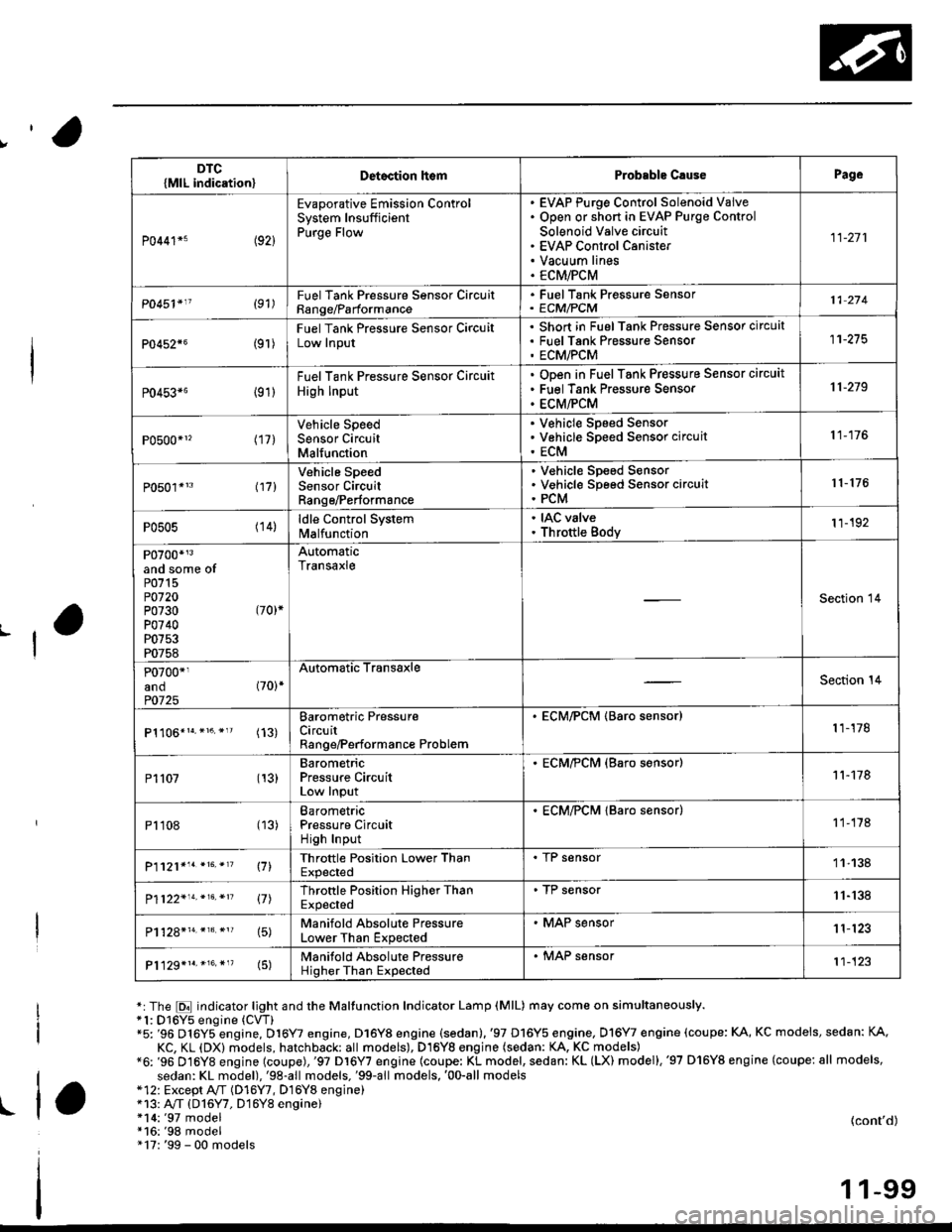
DTC{MlL indication}Detoction lt€mProbable C.usePage
P0441*5 (92)
Evaporative Emission ControlSystem InsufficientPurge Flow
EVAP Purge Control Solenoid VaiveOpen or short in EVAP Purge Control
Solenoid Valve circuitEVAP Control CanisterVacuum linesECM/PCM
11-271
P0451'11 (91)FuelTank Pressure Sonsor CircuitRange/Parformance
. FuelTank Pressure Sensor' ECM/PCM11 274
P0452{6(9r )
Fuel Tank Pressure Sensor CircuitLow Input
Short in FuelTank Pressure Sensor circuatFuel Tank Pres$ure SensorECM/PCM
11-275
P0453*6 {91)
Fuel Tank Pressure Sensor Circuit
High Input
ODen in Fuel Tank Pressure Sensor circuit
Fuel Tank Pressure Sensor
ECM/PCM
11-219
P0500*1, (17)Vehicle SpeedSensor CircuitMalfunction
V€hicle Speed SensorVehicle Speed Sensor circuit
ECM
11-176
P0501*'3 l17l
Vehicle SpeedSensor CircuitRange/Performance
V€hicle Sp€ed SensorVehicle Speed Sensor circuitPCM
r 1- 176
P0505 (14)ldle Control Systemlvl a lfu n ctio n
. IAC valve. Throttle Body11-192
P0700*r3and some ofP0715P0720P0730 (70)*
P0740P0753P0758
AutomaticTransaxle
Section 14
P0700*1and (70)*
P0725
Automatic TransaxleSection 14
(13)Barometric PressureCircuitRange/Performance Problem
. ECM/PCM (Baro sensor)1 1-178
P1107 (13)BarometricPressure CircuitLow Input
. ECM/?CM (Baro s€nsor)11-178
P1108 (13)BarometricPressure CircuitHigh Input
. ECM/PCM lBaro sensor)1 1-178
P1121*'. *16. *'? \71Throttle Position Lower ThanExpected
. I r sensor11-138
P1122'14.*16.*n 17lThrottle Position Higher ThanExpected
. TP sensor11-'138
15)Manifold Absolute PressureLower Than Expected
. MAP sensor1 1'123
P1129*1r.*16.*"(5)Manifold Absolute PressureHigher Than Expected
. MAP sensor't1-123
Page 373 of 2189
PGM-FI System
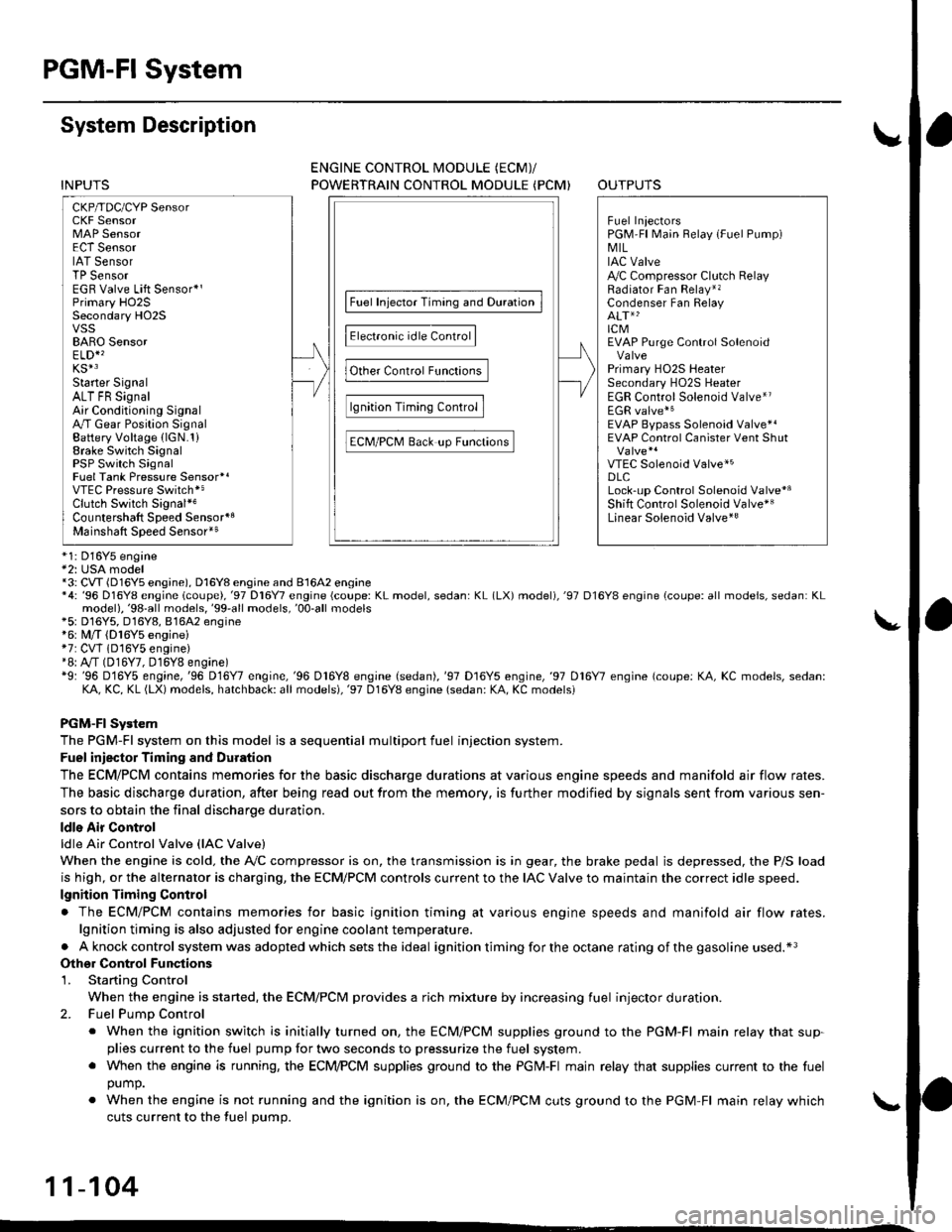
System Description
CKP/TDC/CYP Sensor
MAP Sensor
IAT SensorTP SensorEGR Valve Lift Sensor*'Primary H02SSecondary HO2SVSSBARO SensorELD*'KS€Starter SignalALT FR SignalAir Conditioning SignalA/T Gear Position SignalBattery Voltage {lGN.1}Erake Switch SignalPSP Switch SignalFuel Tank Pressure Sensor*iVTEC Pressure Switch*5Clutch Switch Signal*6Countershaft Speed SensornBMainshaft Speed Sensorrs
-\
----t /
F;ilrr j"-----fi-tri-'r.;l
Fb"t."'i" d" c;;il
F,h"'c;;tr*".io";-l
@."r.l"sc;;ll
EaM/PcM B""k-p F"""till
r\
-:/
Fuel IniectorsPGM-Fl Main Belay {Fuel Pump)MILIAC Valve!y'C Compressor Clutch RelayRadiator Fan Relay*,Condenser Fan RelayALT*'lcMEVAP Purge Control Solenoid
Primary HO2S HeaterSecondary H02S HeaterEGR Control Solenoid Valve*rEGR valve*6EVAP Bypass Solenoid Valve*'EVAP Control Canister Vent Shut
VTEC Solenoid Valve*5DLCLock-up Control Solenoid Valve*aShift Control Solenoid Valve*3Linear Solenoid Valve*3
*1: Dl6Y5 engine*2: USA model*3: CW (D16Y5 ensine), D16Y8 engine and 81642 ensine*4: '96 D16Y8 engine lcoupe),'97 Dl6Y7 engine (coupe: KL model, sedan: KL (LX) model),'97 D16Y8 engine {coupe: all models, sedan: KLmodel),'98-all models,'99'all models,'00-all models+5: D16Y5, D16Y8,816A2 engine*6: M/T (D16Y5 enginei*7: CVT 1D'l6Y5 engine)+8: A/T (D16Y7, D16Y8 engine)*9: '96 D16Y5 engine,'96 D16Y7 engine,'96 Dl6Y8 engine (sedan),'97 D16Y5 engine,'97 Dl6Y7 engine (coupe: KA, KC models, sedan:KA, KC, KL (LX) models, hatchback: all models),'97 D16Y8 engine (sedan: KA, KC modelsi
PGM-FI Sy3lem
The PGM-Fl system on this model is a sequential multipon fuel injection system.
Fuel iniector Timing and Duration
The ECM/PCM contains memories for the basic discharge durations at various engine speeds and manifold air flow rates.
The basic discharge duration, after being read out from the memory. is further modified by signals sent from various sen-
sors to obtain the final discharge duration.
ldle Air Control
ldle Air Control Valve llAC Valve)
When the engine is cold. the A,/C compressor is on, the transmission is in gear, the brake pedal is depressed, the P/S load
is high, or the alternator is charging, the ECM/PCM controls current to the IAC Valve to maintain the correct idle speed.
lgnition Timing Control
. The ECM/PCM contains memories for basic ignition timing at various engine speeds and manifold air flow rates.
lgnition timing is also adjusted for engine coolant temperature.
. Aknockcontrol system was adopted which sets the ideal ignition timing for the octane rating ofthegasoline used.*3
Othgr Control Funqtions
1. Starting Control
When the engine is started, the ECM/PCM provides a rich mixture by increasing fuel injector duration.
2. Fuel Pump Control
. When the ignition switch is initially turned on, the ECM/PCM supplies ground to the PGM-Fl main relay that sup-plies current to the fuel pump for two seconds to pressurize the fuel system.. When the engine is running, the ECI\4PCM supplies ground to the PGM-FI majn relay that supplies current to the fuel
oumo.
. When the engine is not running and the ignition is on, the ECM/PCM cuts ground to the PGM-FI main relay which
cuts current to the fuel pump.
11-104
INPUTS
ENGINE CONTROL MODULE (ECMY
POWERTRAIN CONTROL MODULE (PCM) OUTPUTS
Page 414 of 2189
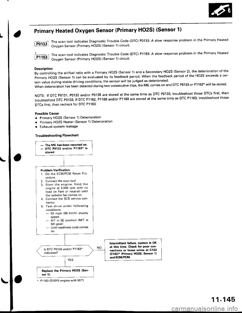
Primary Heated Oxygen Sensor (Primary HO2S) (Sensor 1l
The scan tool indicates Diagnostic Trouble Code (DTC) P0133: A slow response problem in the Primary Heated
Oxygen Sensor {Primary H02S) (Sensor 1) circuit.
The scan tool indicates Diagnostic Trouble code (DTC) Pl163: A slow response problem in the Primary Heated
Oxygen Sensor (Primary HO2S) (Sensor 1)circuit
Description
By controlling the airlfuel ratio with a Primary Ho2S {Sensor 1) and a secondary HO2S {Sensor 2), the deterioration of the
primary HO2S (Sensor 1) can be evaluated by its feedback period. when the feedback period of the Ho2s exceeds a cer-
tain value during stable driving conditions, the sensor will be judged as deteriorated
when deterioration has been detected during two consecutive trips. the MIL comes on and DTC P0133 or P1163* will be stored'
NOTE: tf DTC P0131, P0132 and/or P0135 are stored at the same time as DTC P0133, troubleshoot those DTCS first' then
troubleshoot DTC P0133. lf DTC Pl 162, P1168 and/or P1169 are stored at the same time as DTC P1163, troubleshoot those
DTCS first, then recheck for DTC Pl163.
Possible Cause
o Primary HO2S (Sensor 'l) Deterioration
o Primary HO2S Heater (Sensor 1)Deterioration
. Exhaust system leakage
Troublsshooting Flowchart
tFol3al
I P1163
- The MIL has been reported on- DTC P0133 and/or Pl163* is
stored,
Problem Verilication:1. Do the ECM/PCM Reset Pro
cedure-2. Connect the scan tool
3. Start the engine. Hold the
engine at 3,000 rpm with no
load (in Park or neutral) until
the radiator fan comes on
4. Connect the SCS service con-
nector.5. Test-drive u nder Iollowing
conditions.- 55 mph (88 km/h) steadyspeed- A/f in D position {M/T in
5th gear)
Until readiness code comes
lntermittent failure, 3Y3tem i3 OK
at thi3 time. Ch.ck lol Poor con-
ncctions or loosc wiros at C123
{C145)! lPrimary HO2S, Sensor 1l
and ECM/PCM.
Replace th6 Prim.ry HO2S (Sen'
sor 11.
*: P'l163 (D16Y5 engine with M/T)
11-145
Page 433 of 2189
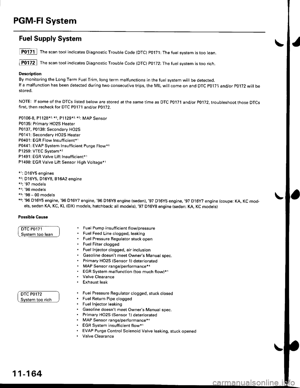
PGM-FI System
Fuel Supply System
D017-il Th""""ntool indicates Diagnostic Troubte Code {DTC) p0171;Thefuet system istoo lean.
1P0172 | fne scan tool indicates Dlagnostic Trouble Code (DTC) P0172:Thefuel system istoo rich.
Description
By monitoring the Long Term Fuel Trim, long term malfunctions in the fuel system will be detected.lf a malfunction has been detected during two consecutive trips, the MIL will come on and DTC P0171 and/or P0172 will bestored.
NOTE: lf some of the DTCS listed below are stored at the same time as DTC P0171 andlot P0172, ltouhleshoot those DTCSfirst. then recheck for DTC P0l7l andlot P0172.
P0106-8, P1128*3. *5, P1129*3 *5 MAP Sensor
P0135; Primary HO2S Heater
P0137. P0138: Secondary HO2S
P0'141: Secondary HO2S Heater
P0401: EGR Flow Insufficient*1
P0441: EVAP System Insufficient Purge Flow*6
P1259: VTEC System*,
P1491:EGR Valve Lift Insufficient*r
P1498: EGR Valve Lift Sensor Hjgh Voltage*r
*r: D16Y5 engines*'�: Dl6Y5, D16Y8, 81642 engine*3: '97 models*a:'96 modelsf 5: '98 - 00 models*6: '96 D16Y5 engine,'96 D16Y7 engine,'96 D16Y8 engine (sedan),'97 D16y5 engine,,97 D16y7 engine (coupe: KA, KC mo+els, sedan KA. KC, KL (DX) models. hatchback; all models),'97 D16Y8 engine (sedan: KA, KC models)
Possible Cause
DTC P0'171
loo lean
DTC P0172
too rach
Fuel Pump insuff icient f lovpressure
Fuel Feed Line clogged, leaking
Fuel Pressure Regulator stuck open
Fuel Filter clogged
Fuel Injector clogged, air inclusion
Gasoline doesn't meet Owner's Manual spec.
Primary HO2S (Sensor 1) deteriorated
MAP Sensor range/performance*.
EGR System malfunction (too much flow)*1
Valve Clearance
Exhaust leak
Fuel Pressure Regulator clogged, stuck closed
Fuel Return Pipe clogged
Fuel Injector leaking
Gasoline doesn't meet Owner's Manual spec.Primary HO2S (Sensor 1) deteriorated
MAP Sensor range/performance*a
EGR System insufficient flow*1
EVAP Purge Control Solenoid Valve leaking, stuck opened
Valve Clearance
11-164
Page 434 of 2189
t
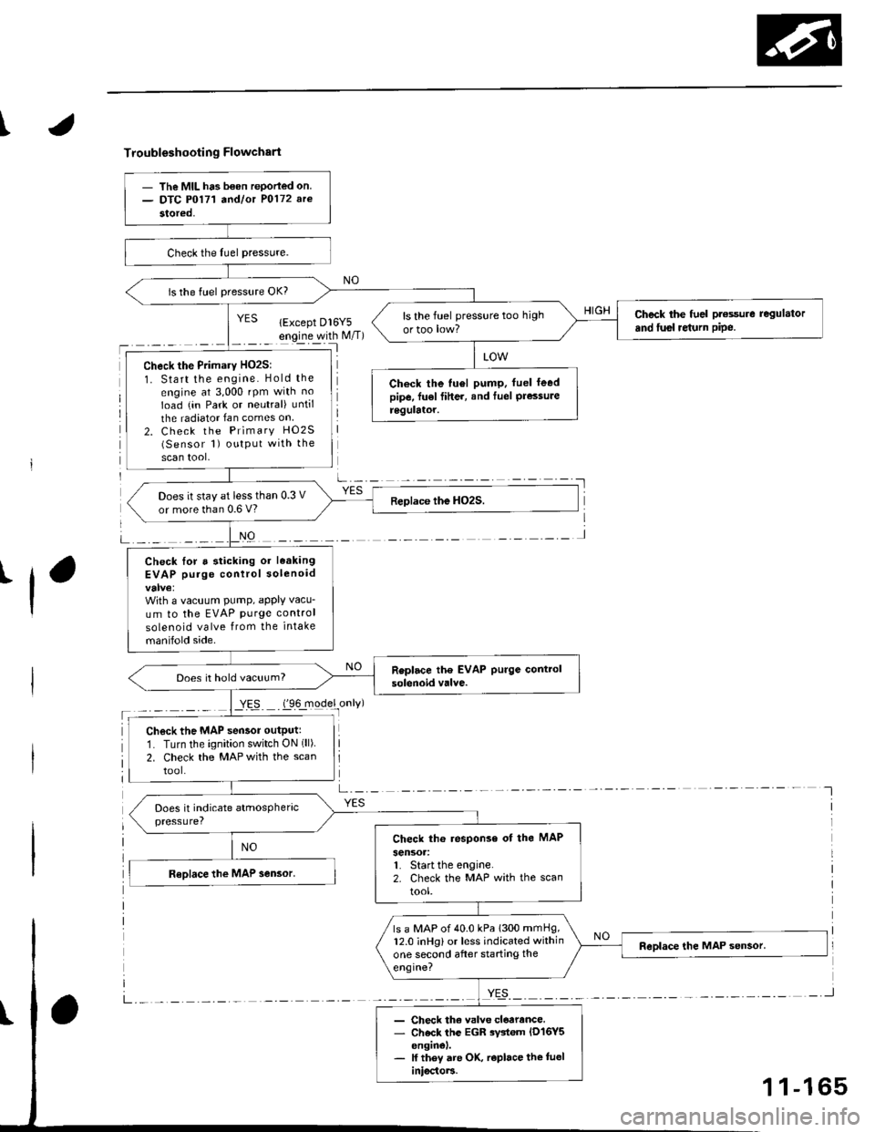
Troubleshooting Flowchart
'l
NO
a-,-:- -
YES
- The MIL ha3 b€on rePorled on.- DTC P0171 a^dlot P0172 arc
stored,
is the fuel pressure OK?
Check the fuel pt€ssure regulator
and fusl re{urn pipe.ls the fuel pressure too high
ortoo low?
Check the Primary HO2S:
1. Start the engine. Hold the
engine at 3,000 rpm with no
Ioad (in Park or neutral) until
the radiator Ian comes on
2. Check the Primary HO2S(Sensor 1) output with the
scan tool,
Check the tu6l pump. fuel leedpipe, fu€l fiher, and Iuel Pressureregulator.
Does it stay at less than 0.3 V
or more than 0.6 V?
Check lor a sticking or leaking
EVAP purge control solenoid
With a vacuum PumP, aPPIY vacu-
um to the EVAP purge control
solenoid valve from the intake
manifold side.
Does it hold vacuum?
Check the MAP sensor outputr
1. Turn the ignition switch ON (ll)
2. Check the MAP with the scan
tool.
Check th6 response of the MAP
sensoa:1. Start the engine.2. Check the MAP with the scan
tool.
ls a MAP of 40.0 kPa 1300 mmHg,12.0 inHg) or less indicated within
one second after starting the
engine?
- Check th€ valve cloarance.- Check the EGR rystem lD16Y5enginel.- lf they are OK, r€place the tueliniocto]3.
1 1-165
Page 435 of 2189
PGM-FI System
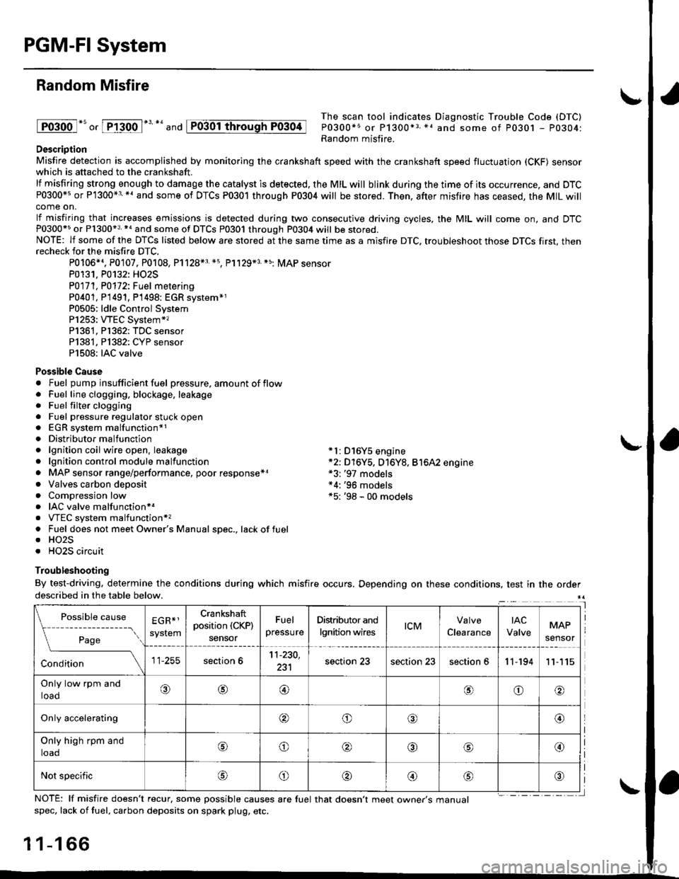
Random Misfire
lFoioo l*u o, [FTioo l*' *' and
The scan tool indicates Diagnostic Trouble Code (DTC)
P0300*5 or P1300*3 *1 and some of P0301 - P0304:Random misfire.Description
Misfire detection is accomplished by monitoring the crankshaft speed with the crankshaft speed fluctuation (CKF) sensorwhich is attached to the crankshaft.
lf misfiring strong enough to damage the catalyst is detected. the MIL will blink during the time of its occurrence, and DTCP0300*5 or P1300*3'*' and some of DTCs P0301 through P0304 will be stored. Then, after misfire has ceased, the MIL willcome on.
lf misfiring that increases emissions is detected during two consecutive driving cycles, the MIL will come on, and DTCP0300*5 or P1300*3 *a and some of DTCS P0301 through P0304 will be stored.NOTE: lf some of the DTCS listed below are stored at the same time as a misfire DTC. troubleshoot those DTCS first, thenrecheck for the misfire DTC.
P0106*4. P0107. P0108, P1128*3 *5, Pl129*3 *5; MAP sensorP0131. P0132: HO2S
P0171, P0112i Fuel metering
P0401, P 1491, P1498: EGR svstem*1P0505: ldle Control SystemP1253: VTEC System*,P1361, P1362: TDC sensorP1381, Pl382: CYP sensorP1508: IAC valve
Possible Cause. Fuel pump insufficient fuel pressure, amount of flow. Fuel line clogging, blockage, leakage. Fuel filter clogging. Fuel pressure regulator stuck open. EGR system malfunction*1. Distributormalfunction. lgnition coil wire open. leakage *l: D16Y5 engine. lgnition control module malfunction *2: D16Y5, D16Y8, Bt6A2 engine. MAP sensor range/performance, poor response*r *3: '97 models. Valves carbon deposit *4;'96 models. Compression low *5: '98 - 00 models. IAC valve malfunctionr.. VTEC system malfunction*,. Fuel does not meet Owner's Manual spec., lackoffuel. HO2S. HO2S circuit
Troubleshooting
By test-driving, determine the conditions during which misfire occurs, Depending on these conditions, test in the orderdescribed in the table below.
Possible
- --^ ---
rage
causeEGR*1
system
Crankshaft
position (CKP)
sensor
Fuel
pressure
Distributor and
lgnition wirestcMClearance
tAc
ValveMAP
sensor
section 611-230,
231section 23section 23section 611-19411
Only low rpm and
loado@@oo
Only accelerating@o@@
Only high rpm and
toaooo@
Not specificoo@
NOTE: lf misfire doesn't recur, some possible causes are fuel that doesn't meet owne/s manualspec, lack of fuel, carbon deposits on spark plug, etc.
1 1-1 66
I
P0304
Page 436 of 2189
I
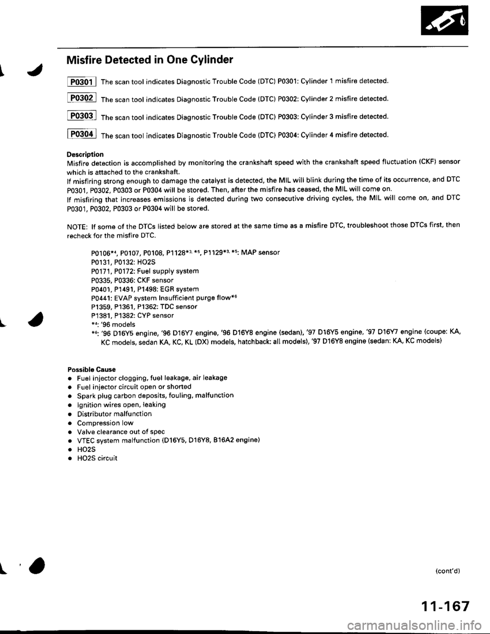
Misfire Detected in One Cylinder
P0301 | The scan tool indicates Diagnostic Trouble Code (DTC) P0301: Cylinder 1 misfire detected.
[F03O2l 16"""untool indicates Diagnostic Trouble code (DTc) P0302: Cylinder2 misfire detected.
[FO3Ofl 16" ".un toot indicates Diagnostic Troubte Code (DTC) P0303; Cylinder 3 misfire detected.
I P0304 I ths..rr tool indicates Diagnostic Trouble Code (DTC) PO3O4: Cylinder 4 misfire detected.
D€scription
lMisfire detection is accomplished by monitoring the crankshaft speed with the crankshaft speed fluctuation (CKF) sensor
which is attached to the crankshaft,
lf misfiring strong enough to damage the catalyst is detected, the MIL will blink during the time of its occurrence, and DTC
PO3O1, P0302, PO3O3 or P0304 will be stored. Then, after the misfire has ceased, the MIL will come on.
lf misfiring that increases emissions is detected during two consecutive driving cyclss, the MIL will come on, and DTC
P0301, P0302, P0303 or P0304 will be stored.
NOTE: lf some of the DTCS listed below are stored at the same time as a misfire DTC, troubleshoot those DTCS first, then
recheck for the misfire DTC.
PO106*1, P0107, P0108. P1128*3'*5, P1129*3'*5: MAP sensor
P0131, P0132: HO2S
P0171, P0172iFuel suppiy system
P0335, P0336: CKF sensor
P0401. P1491, P1498: EGR system
P0441: EVAP system Insufficient purge flow*6
Pl359. P1361. Pl362: TDC sensor
P1381. Pl382: CYP sensor*o: '96 models*6: '96 D16Y5 engine,'96 D16Y/ engine,'96 D16Y8 engine {sedan),'97 D16Y5 engine,'97 D16\4, engine (coupe: KA,
KC models, sedan KA. KC, KL (DX) models, hatchback:all models),'97 D16Y8 engine (sedan: KA, KC models)
Possible Cause
. Fuel injector clogging, fuel leakage, air leakage
. Fuel injector circuit open or shorted
. Spark plug carbon deposits, fouling, malfunction
. lgnition wires open. leaking
. Distributor malfunction
. ComDression low
. Valve clearance out of spec
. VTEC system malfunction (D16Y5, D16Y8. 81642 engine)
. HO2S
. HO2S circuit
(cont'd)
11-167
r'a