shift link HONDA CIVIC 1998 6.G Workshop Manual
[x] Cancel search | Manufacturer: HONDA, Model Year: 1998, Model line: CIVIC, Model: HONDA CIVIC 1998 6.GPages: 2189, PDF Size: 69.39 MB
Page 72 of 2189
ILubrication Points
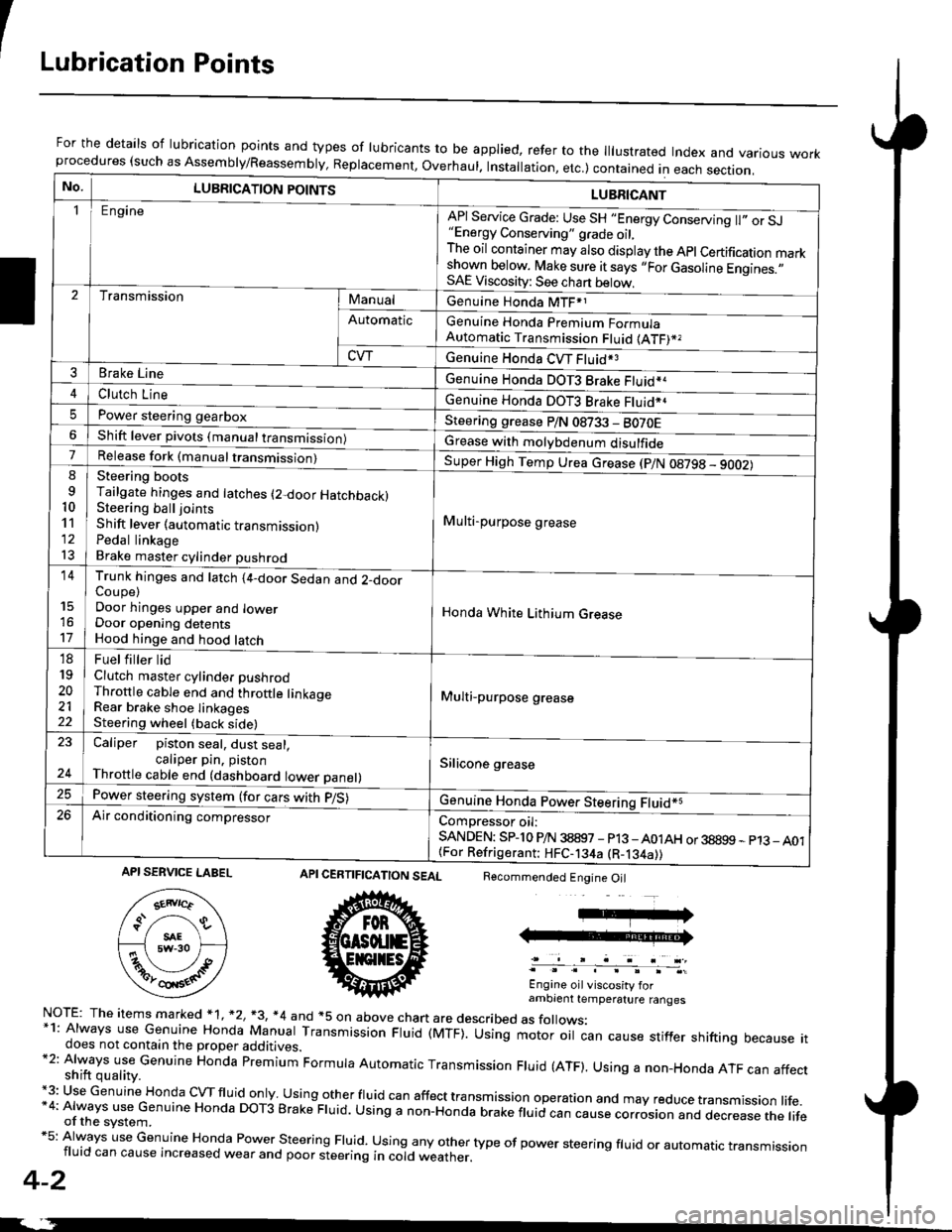
For the details of lubrication points and types of lubricants to be applied, refer to the lllustrated Index and various workprocedures (such as Assembly/Reassembly, Replacement, Overhaul. Installation, etc.) contained in each section.
No.LUBRICATION POINTS
Engine
LUBRICANT
"Energy Conserving" grade oil,The oil container may also display the Apl Certification markshown below. Make sure it says ,,For Gasoline Engines.,,SAE Viscosity: See chart below,
I
TransmissionManualGenuine Honda MTF*1
Genuine Honda Premium FormulaAutomatic Transmission Fluid (ATF)*,
Genuine Honda CVT Fluid*3
Genuine Honda DOT3 Brake Fluid*a
Automatic
CVT
3Brake Line
ClL,tci t""e4
I
Genuine Honda DOT3 Brake Fluid*aPower steering gearboxSteering grease P/N 08733 - BO70EShift lever pivots (manual transmission)Grease with molybdenum disulfide7-:ti
9
10'l'l
l3
14
't7
18
19
20
2122
Release fork (manual trancmi
Shift lever (automatic transmission)Pedal linkageBrake master cylinder pushrod
Super High Temp Urea crease (p/N 08798 - 9OO2)
i Multi-purpose grease
I
I
Honda White Lithium Grease
Multi-purpose grease
Silicone grease
@
Trunk hinges and latch (4-door Sedan and 2-doorCoupe)Door hinges upper and lowerDoor opening detentsHood hinge and hood latch-FUet T ter ttd
Clutch master cylinder pushrodThrottle cable end and throttle linkageRear brake shoe linkagesSteering wheel (back side)
23
E-
Caliper piston seal, dust seal,caliper pin. pistonThrottle cable end (dashboard lower panel)
Power steering system (for cars with p/S)
Air conditioning compressorComDressor oil:SANDEN: SPlo P/N 38897 - p13 -A01AH or 38899 - p13_ A01{For Refrigerant: HFC-134a (R-134a))
CERTIFICATION SEAL
ffi
NorE: The items m arked * 1, *2, +3, *4 and +5 on above chan are described as folows:*1: Always use Genuine Honda Manual Transmission Fluid (MTF). Using motor oil can cause stiffer shifting because itdoes not contain the proper additives.*2: Always use Genuine Honda premium Formula Automatic Transmission Fluid (ATF). Using a non-Honda ATF can affectshift quality.+3: Use Genuine Honda cVTfluid only usingotherfluid can affect tra nsmission operation and may reduce transmission life.*4: Always use Genuine Honda DoT3 Brake Fluid. Using a non-Honda brake fluid can cause corrosion and dec.ease the lifeof the svstem.*5: Always use Genuine Honda Power steering Fluid. using any other type of power steering fluid or automatrc transmissionfluid can cause increased wear and poor steering in cold weather.
4-2
Recommended Engine Oil
Engine oil viscosity forambrent temperature ranges
API SERVICE LABEL
Page 730 of 2189
Symptom-to-Component Ghart
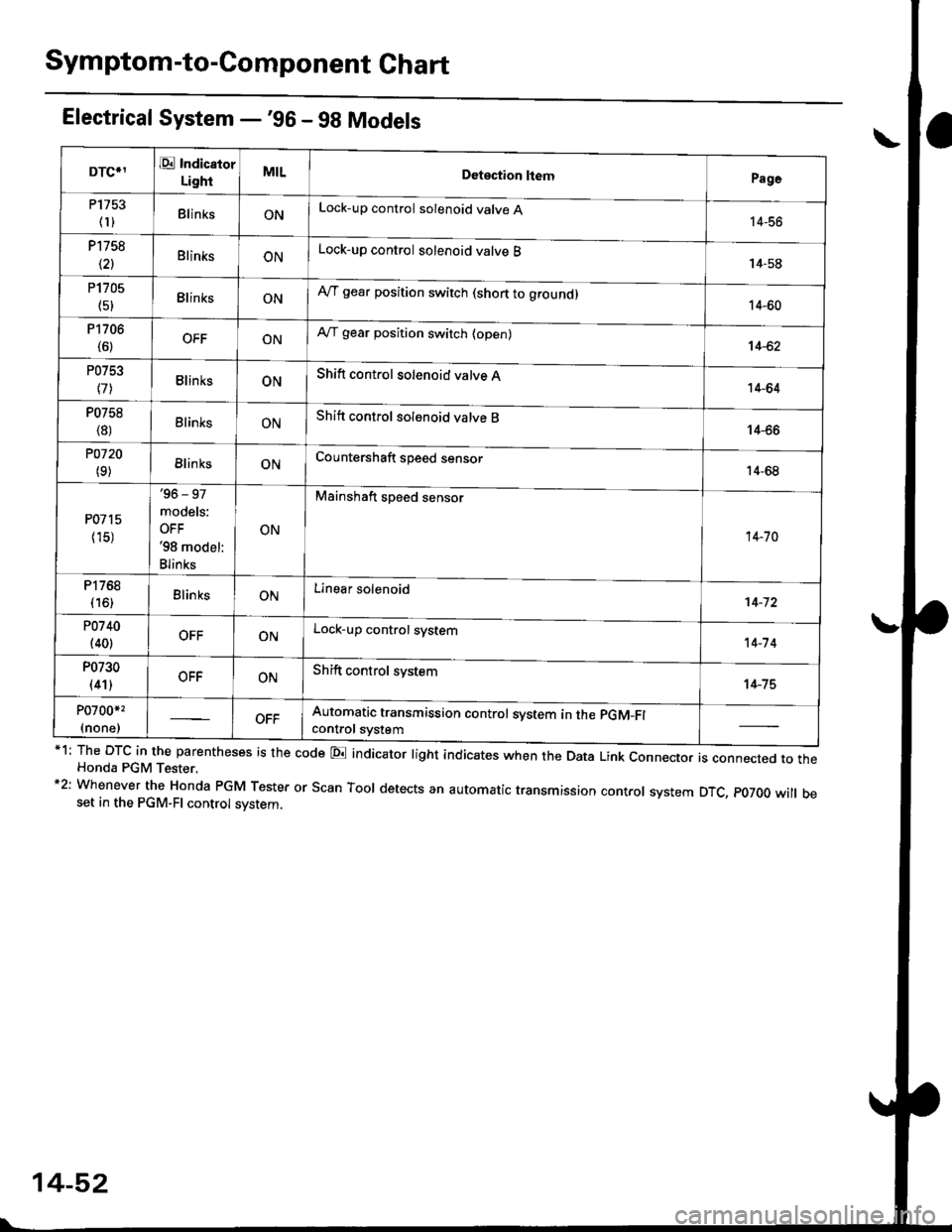
Electrical System -'gG - 98 Models
*1: The DTC in the parentheses is the code E indicator light indicates when the Data Link connector is connected to theHonda PGM Tester.*2: Whenever the Honda PGM Tester or Scan Tool detects an automatic transmission control system DTC, p07OO will beset in the PGM-FI control svstem.
DTCIIE Indicaior
LightMILDotection ltemPage
P1753
fl)BlinksONLock-up control solenoid valve A14-56
P1758
\21BlinksONLock-up control solenoid valve B14-58
P1705
(51BlinksONAy'T gear position switch (short to groundl14-60
P1706
(6)OFFONA,/T gear position switch (open)14-62
P0753
l7lBlinksONShift control solenoid valve A14-64
P0758
{8)ElinksONShift control solenoid valve B14-66
POl20
(9)BlinksONCountershaft speed sensor14-68
P0715
{15)
'96 - 97
models:
OFF'98 model:
Blinks
ON
Mainshaft speed sensor
14-70
P1768
{16)BlinksONLinear solenoid't 4-72
P0740
(40)OFFONLock-up control system14-7 4
P0730
(41)OFFONShift control system14-75
P0700*,
(none)Automatic transmission control svstem in the pGM-Fl
control svstem
14-52
Page 731 of 2189
SYmPtom
E indicator light does not come on tor two seconds after ignition
switch is first turned ON {ll}.
E indicator light is on constantly (not blinking) whenever the ignition
switch is ON (ll).
Shift lever cannot be moved from @ position with the brake pedal
depressed.
Inspection Ref. Page
11-16
14-78
Inspection't4-79
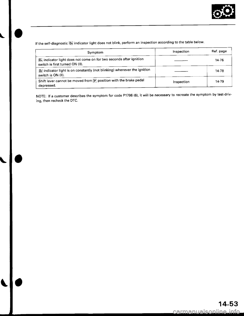
lf the self-diagnostic l-d indicator light does not blink, perform an inspection according to the table below.
NOTE: lf a customer describes the symptom for code Pl706 {6), it will be necessary to recreate the symptom by test-driv-
ing, then recheck the DTC.
14-53
Page 732 of 2189
Symptom-to-Component Chart
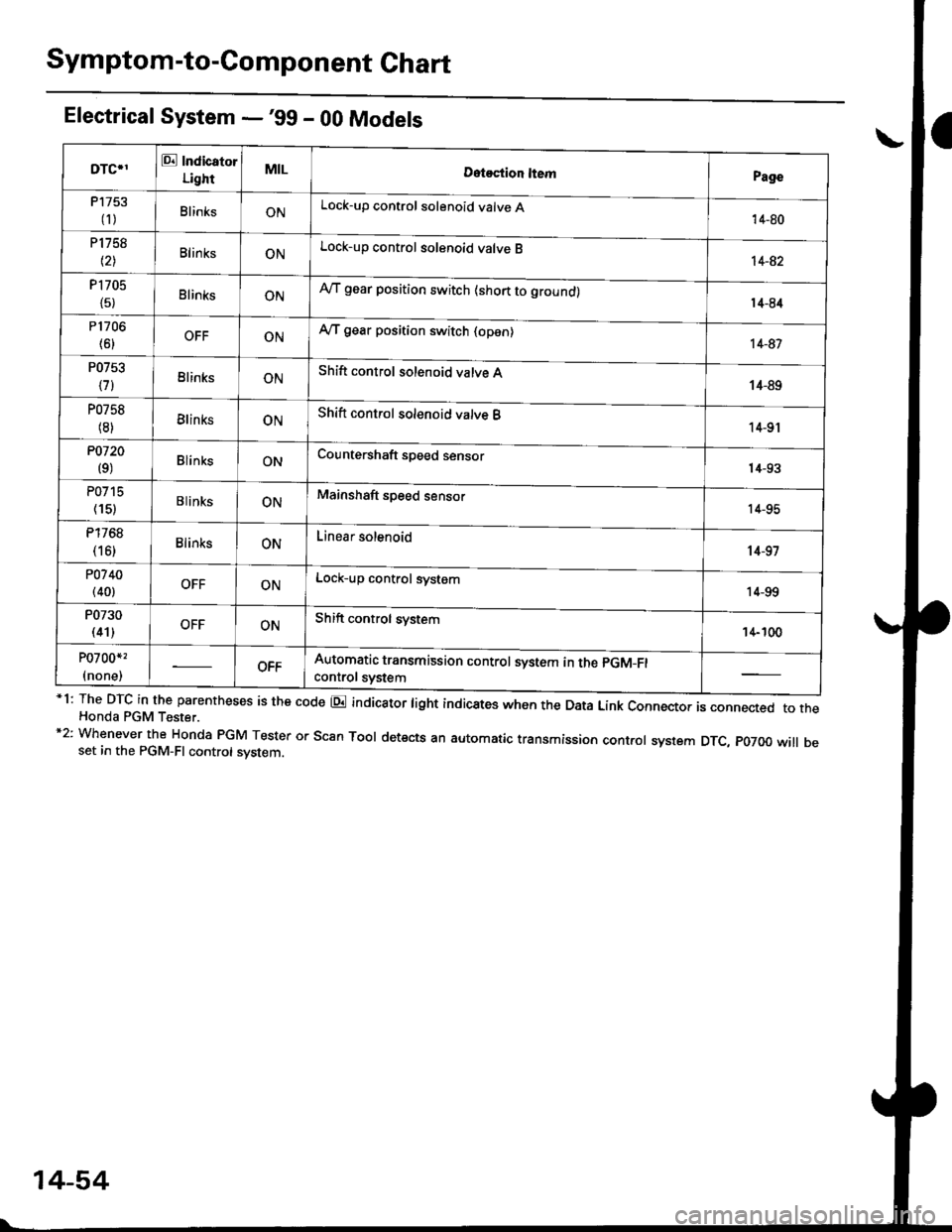
Electrical System -'99 - 00 Models
*1: The DTc in the parentheses is the code E indicator tight indicates when the Data Link connector is connected to theHonda PGM Tester.*2: Whenever the Honda PGM Tester or scan Tool detects an automatic transmission control system DTc, p07oo will beset in the PGM-FI control svstem
DTC*IE Indicator
LightMILDotostion ltemPage
P1753
fi)BlinksONLock-up control solenoid valve A'14-80
P1758
t2lBlinksONLock-up control solenoid valve B14-82
P1705
{5}BlinksONAy'T gear position switch {short to ground)14-84
P1706
(6)OFFONy'VT gear position switch {open)14-81
P0753
\71BlinksONShift control solenoid valve A14-89
P0758
(8)BlinksONShift control solenoid valve B14-9r
P0720
(9)BlinksONCountershaft speed sensorr4-93
P0715
(15)B linksONMainshaft speed sensor14-95
P1768
(16)BlinksONLinear solenoid't 4-97
PO7 40(40)OFFONLock-up control system14-99
P0730
(41)OFFONShift control svstem14- 100
P0700*,
(none)OFFAutomatic transmission control system in the pGM_Fl
controt svstem
14-54
Page 733 of 2189
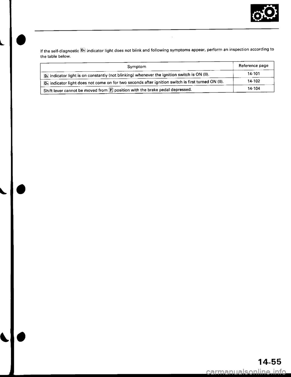
E i"dl.r." fiSh, 1."""". y{*fu
Reference page
14- 101
lE indicator light does not come on for two seconds after ignition switch is first turned oN (ll).14-102
Shift lever cannot be moved from E position with the brake pedal deprsssed'14-104
lf the self-diagnostic E indicator light does not blink and following symptoms appear, perform an inspection according to
the table below.
14-55
Page 738 of 2189
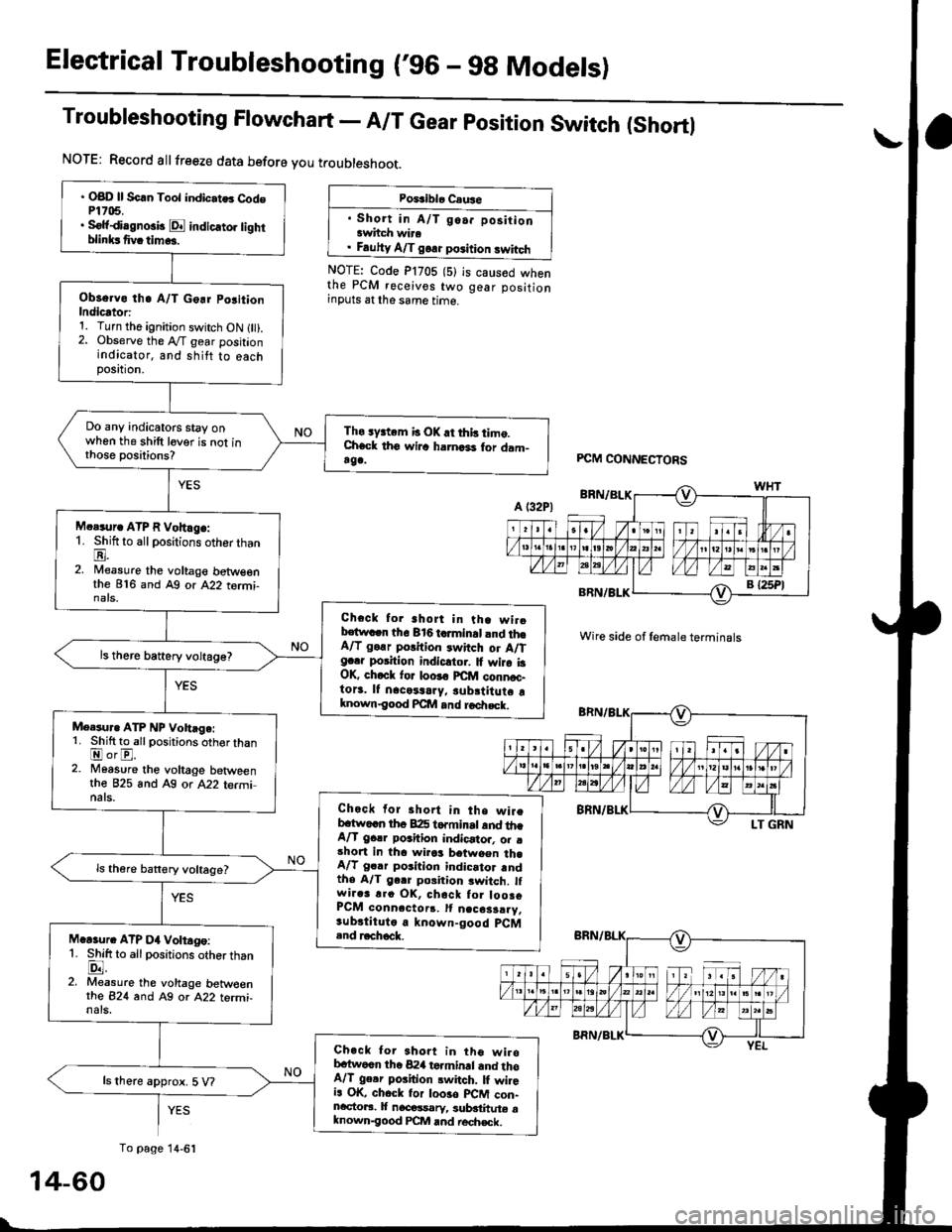
Electrical Troubleshooting ('96 - 9g Models)
Troubleshooting Flowchart - A/T Gear position Switch (Shortl
NOTE: Record allfreeze data before you troubleshoot.
Poiriblo Caus6
. Short in A/T go.. positionawhch wira. Fauhy A/T goa. position swhch
NOTE: Code P1705 (5)the PCM receives twoinputs at the same time.
is caused whengear position
' OBD ll Scln Toot indic.tes Cod6P1705.. Sofidi.gno3b E indicato] tighrblinksfivatim...
Observo th. A/T Go.r po3ition
Indicator:1. Turn the ignition switch ON l).2. Observe the A"/T gear positionindicator, and shitt to eachposttron,
Do any indicatoG stay onwhen the shift lever is not inthose positions?
Tho sy3tem b OK.t this timo.Check th6 wilc harnari for dam-rga.
M.r.ur. ATP R Vohlge:1. Shift to all positions otherthanE.2. Nileasure the voltage betweenthe 816 and Ag or A22 tormi-nats,
Check for short in tha wirobstwacn the 816 tcrminal and th6A/T go.r porition rwitch or A/Tg..r position indicltor. It wira i3OK, ch.ck for loo!€ FCfit connoc-to13. lf nacetaary, subrtitute aknown€ood Pcllt and roa|rsck.
ls there battery voltage?
Meesur. ATP NP Vohage:1. Shift to allpositions oth€r thanEorE.2. Moasure the voltage betweenthe 825 and A9 or A22 terminats.Check for short in the wireb.tw..n th6 B:I5 torminrt and th.A/T gclr poahion indicator. o. .short in tha wirrs between th.A/T gclr position indicator rndthe A/T gerr poiition switch. lfwir.3 r.o OK, chack tor loosoPCM conn.ctorr. It n.cosarry.sub.tituto a known-good pCM.nd r.chock.M.Gur. ATP D4 Voltago:1. Shift to allpositions otherthanlD.l.2. Measure the voltage betw€enrhe 824 and Ag or A22 termi-nals.
Check tor 3hort in tho wirobc{wocn the 824 terminrl and thoA/T ge.r poiition switch. lI wileia OK, chock tor loo3o plCM con-ncctoaa. It nacossarv, sublthute aknown-good PCM and rech€ck.
ls there approx. 5 V?
PCM CONNECTORS
Wire side of female terminals
YES
To page 14-6':
14-60
Page 740 of 2189
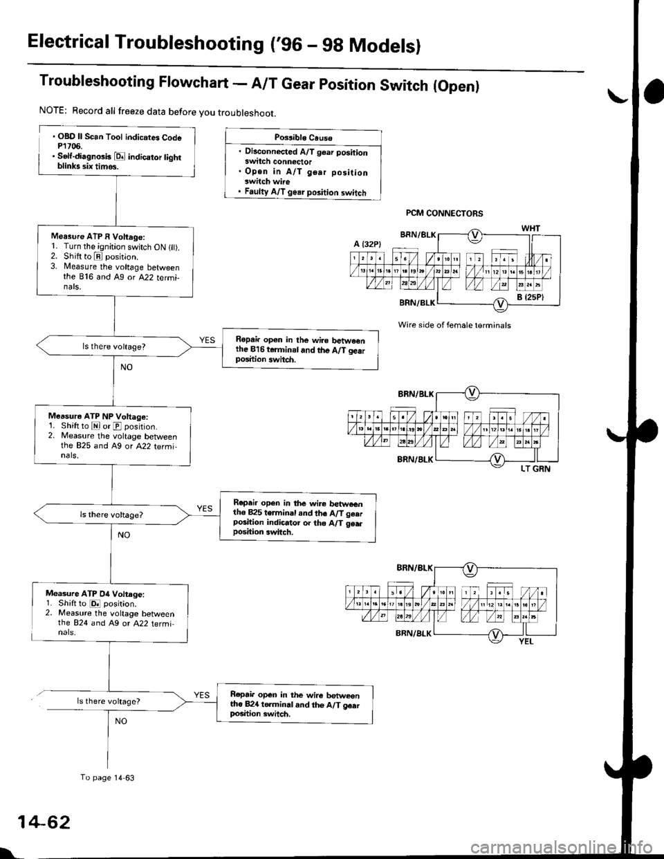
Electrical Troubleshooting ('96 - gg Modelsl
Troubleshooting Flowchart - A/T Gear position Switch (Open)
. OBD ll Scan Tool indicates CodeP1706.. Self-di.gnosk E indicator tightblinks six timos.
Measure ATP 04 Voltege:1. Shiftto E position.2. Measure the voltage betweenthe 824 and A9 or A22 terminals,
ls there voltage?
Possible Causo
. Disconnected A/T gear positionswitch conn€ctor. Open in A/T gear positionswitch wire. Faulty A/T gear position switch
Wire side of female terminals
NOTE: Record all freeze data before you troubleshoot.
Moasure ATP I Voltage:1. Turn the ignition switch ON 1 ).2. Shift to E position.3. Measure the voltage betweenthe B'f6 and Ag ot A22 tetmi-nats.
Ropai. op€n in the wire betwe€nthe Bl6 terminal.nd the A/T gearposition swhch.
Measur€ ATP NP Voltage:1. Shift to E or E position.2. Measure the voltage betweenthe 825 and A9 or A22 termi,nals,
Repeir open in the wir€ betweentho B25 terminal and th6 A/T geerposition indicator or tho A/T 96.rposition 3witch.
Rcpair open in the wire betweentto 82{ to.minal and th6 A/T geatlrosition 3witch.
To page 14 63
PCM CONNECTORS
NO
1
L
+62
Page 742 of 2189
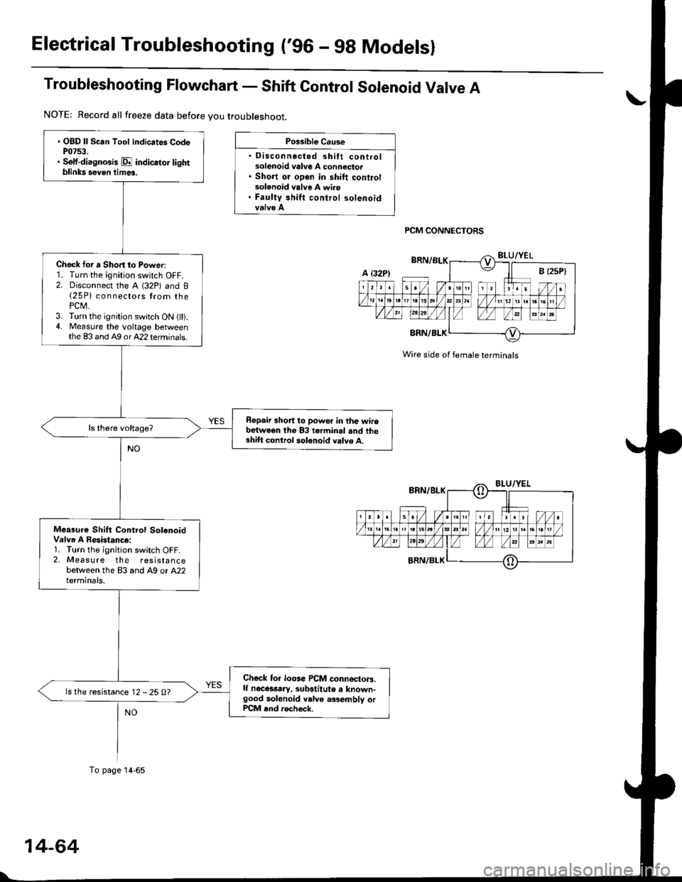
Electrical Troubleshooting ('96 - 98 Modelsl
Troubleshooting Flowchart - Shift Gontrol Solenoid Valve A
Po$ible Cau3e
. Disconnected shift controlsolenoid valve A connector. Short oi open in shift controlsolenoid valve A wire. Faulty shirt control solenoid
PCM CONNECTORS
' OBD ll Scan Tool indicates CodeP0753.. Sett{iagnosis E indicator lightblinks seven tim6.
Check tor a Short to Power:1. Turn the ignition switch OFF.2. Disconnect the A (32P) and B{25 Pi connectors trom thePCM.3. Turn the ignition switch ON {ll).4. Measure the voltage betweenthe 83 and A9 orA22 terminals.
Repair short to powe. in the wir6between the 83 terminal .nd theshift control solonoid valvo A.
Moa3ure Shift Control SolenoidValve A Resistanc€:1. Turn the ignition switch OFF.2, Measure the resistancebetween the 83 and A9 or A22terminals.
Ch€ck for loose PCM connectors.lf n€c6srry, subatitute a known-good solenoid valve a3,sembly orPCM end rocheck.
ls the resistance 12 - 25 0?
NOTE: Record all freeze data before you troubleshoot.
A t32Pl
To page 14-65
Wire side ol female terminals
Page 744 of 2189
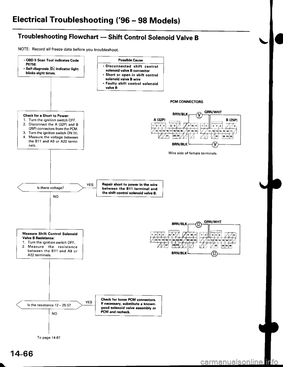
Electrical Troubleshooting ('96 - g8 Modelsl
Troubleshooting Flowchart - Shift Control Solenoid Valve B
Possible Cause
' Disconnected shift controlsolenoid valve I connectol. Short or open in shift controlsolenoid valve B wire. Faulty shift control 30lenoidvalve B
PCM CONNECTORS
Wire side ot female terminals
. OBD ll Scan Tool indic.tes CodeP0758.. Solt-diagnosis E indicator lightblinks eight times.
Chock for a Short to Power:1. Turn the ignition swatch OFF.2. Disconnect the A (32P) and B(25P)connectors from the PCM.3. Turn the ignition switch ON (ll).4. Measure the voltage betweenthe 811 and Ag or A22 termi-nals,
Repair short to powar in the wirebotwcen the 811 torminal andthe shift control solenoid valve 8.
Measure Shift Cont.ol SolenoidValve B Resktance:1. Turn the ignition switch OFF.2, Meas u re the resistancebetween the Bll and A9 orA22 terminals.
Checl for loose PiCM connector3.lf nec€ssary, sub3titute a known-good solenoid v.lve assembly olPCM and recheck.
ls the resistance 12 - 25 O?
NOTE: Record allfreeze data before you troubleshoot,
A t32P)
To page 14 67
\
Page 756 of 2189
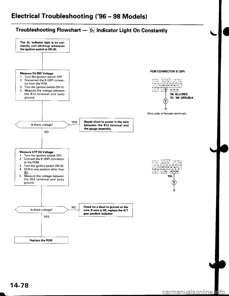
Electrical Troubleshooting ('96 - 98 Models)
Th6 E indicstor light is on con-st.ntly {not blinkingl wheneveithe ignition switch is ON lll).
Measure 04 IND Voltage:1. Turn the ignition switch OFF.2. Disconnect the B 125P) connec-tor from the PCM.3. Turn the ignition switch ON (ll).
4. Measure the voltage betweenthe 813 terminal and bodyground,
Repair 3hort to pow€. in the wirobetween the 813 terminal endthc gauge asiombly.
Meaiure ATP Dil Voltage:1. Turn the ignition switch OFF.2. Connect the I (25P) connectorto the PCM.3. Turn the ignition switch ON (ll).4. Shiftto any position otherthan
5. Measure the voltage betweenthe 824 terminal and bodygrou nd.
Check for a short to ground on thowir6. It wire i3 OK, .eplac6 the A/Tgoar po3ition indbator,
Troubleshooting Flowchart - E Indicator Light On Constantly
a!
PCM CONNECTOR B (25P)
Wire side of lemale terminals
l.
14-7A