mat HONDA CIVIC 1999 6.G Workshop Manual
[x] Cancel search | Manufacturer: HONDA, Model Year: 1999, Model line: CIVIC, Model: HONDA CIVIC 1999 6.GPages: 2189, PDF Size: 69.39 MB
Page 607 of 2189
Synchro Sleeve,
Synchro Hub
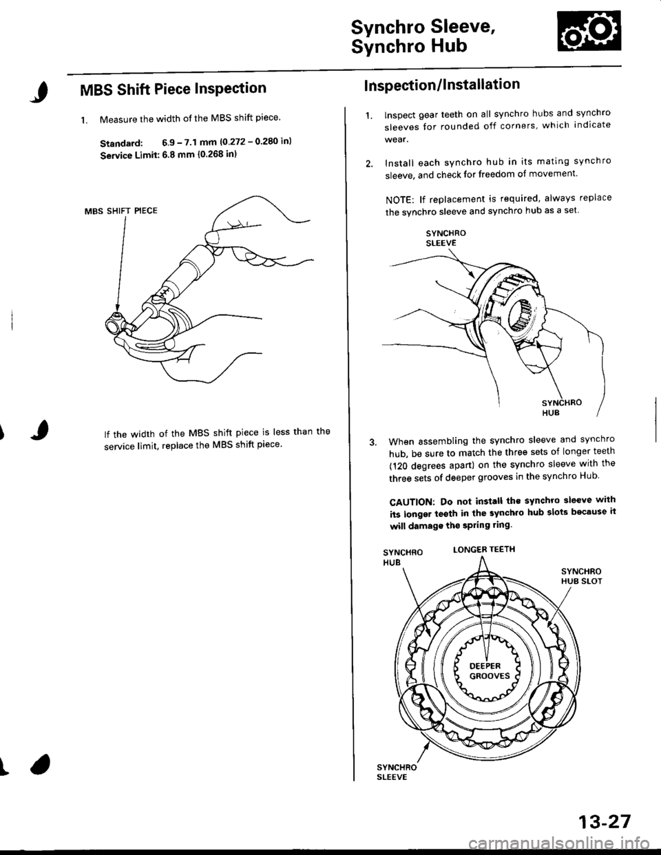
MBS Shift Piece InsPection
1. Measure the width of the MBS shift piece.
Standard; 6.9 - 7.1 mm 10 272 - 0.280 inl
Service Limit: 6.8 mm {0.268 inl
lf the width of the MBS shift piece is less than
service limit, replace the MBS shift piece'
t
I nspection/l nstallati on
'1.lnspect gear teeth on all synchro hubs and synchro
sleeves tor rounded off corners, which indicate
Install each synchro hub in its mating synchro
sleeve, and check for freedom of movement.
NOTE: lf replacement is required, always replace
the synchro sleeve and synchro hub as a set.
SYNCHROSLEEVE
When assembling the synchro sleeve and synchro
hub, be sure to match the three sets of longer teeth
(120 degrees apart) on the synchro sleeve with the
three sets of deeper grooves in the synchro Hub
CAUTION: Do not install th€ sYnchro sleeve with
its longsr t€sth in the synchro hub slots bocause ii
will damage ths spring ring.
LONGER TEETH
13-27
Page 608 of 2189
Synchro Ring, Gear
Inspection
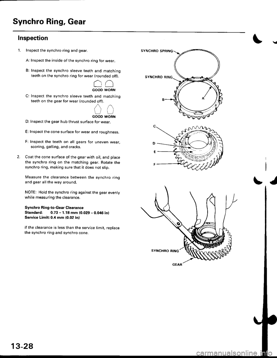
1. Inspect the synchro ring and gear.
A: Inspect the inside of the synchro ring for wear.
B: Inspect the synchro sleeve teeth and matching
teeth on the synchro ring for wear (rounded off).
r- /-\
oioi *-o*
C: Inspect the synchro sleeve teeth and matching
teeth on the gear for wear (rounded off).
,
UtJGOOO WORN
D: Inspect the gear hub thrust surface for wear.
E: Inspect the cone surface for wear and roughness.
Fr Inspect the teeth on all gears for uneven wear,
scoring, galling, and cracks.
2. Coat the cone surface of the gear with oil. and place
the synchro ring on the matching gear. Rotate the
synchro ring. making sure that it does not slip.
Measure the clearance between the synchro ring
and gear all the way around.
NOTE: Hold the synchro ring against the gear evenly
while measuring the clearance.
Synchro Ring-to-Gear Clearance
Standard: 0.73 - 1.18 mm {0.029 - 0.046 in}
Service Limit 0.4 mm {0.02 in)
lf the clearance is less than the service limit, replace
the synchro ring and synchro cone.
SYNCHRO
SYNCHRO
\a
r/
13-28
Page 612 of 2189
Differential
Thrust Shim Adjustment
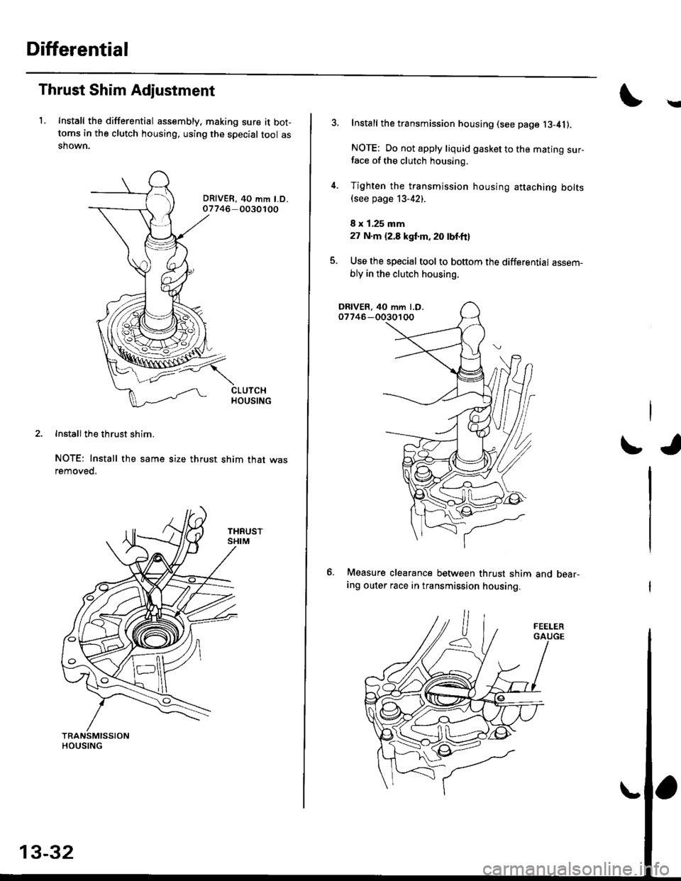
1. Install the differential assembly, making sure it bot-toms in the clutch housing, using the special tool asshown.
DRIVER, 40 mm LD.07746 0030100
Install the thrust shim.
NOTE: Install the same size thrust shim that wasremoved.
Y
Install the transmission housing (see page l3-41).
NOTE: Do not apply liquid gasket to the mating sur-face of the clutch housing.
Tighten the transmission housing attaching bolts(see page 13-42).
I x 1,25 mm
27 N.m (2.8 kgt'm, 20 lbf'ft}
Use the special tool to bottom the differential assem-
bly in the clutch housing.
tJ
6. Measure clearance between thrust shim
ing outer race in transmission housing.
and bear-
13-32
Page 621 of 2189
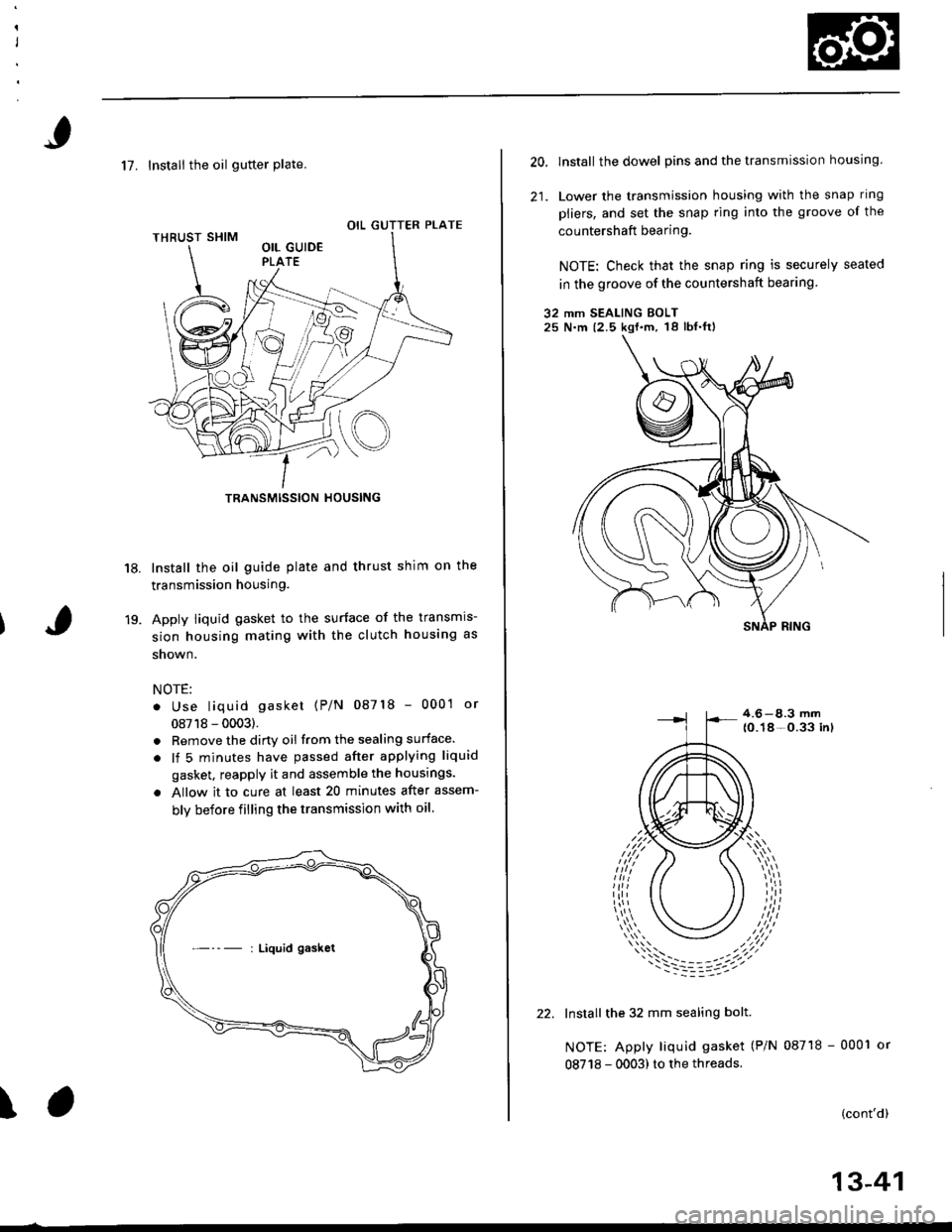
17. Instali the oil gutter Plate.
Install the oil guide plate and thrust shim on the
transmission housing.
Apply Iiquid gasket to the surface of the transmis-
sion housing mating with the clutch housing as
shown.
NOTE:
. Use liquid gasket {P/N 08718 - 0001 or
08718 - 0003).
. Remove the dirty oil fromthesealing surface.
. lf 5 minutes have passed after applying liquid
gasket, reapply it and assemble the housings.
. Allow it to cure at least 20 minutes after assem-
bly before filling the transmission with oil.
18.
19.
\
OIL GUTTER PTATE
TRANSMISSION HOUSING
Liquid gasket
20.lnstall the dowel pins and the transmission housing.
Lower the transmission housing with the snap ring
pliers, and set the snap ring into the groove of the
countershaft bearing.
NOTE: Check that the snap ring is securely seated
in the groove of the countershaft bearing
32 mm SEALING EOLT25 N.m (2.5 kgf.m, 18lbf.ftl
4.6 -8.3 mm10.14-0.33 inl
Install the 32 mm sealing bolt.
NOTE: Apply liquid gasket (P/N 08718 - 0001
08718 - 0003) to the threads.
(cont'd)
22.
13-41
Page 646 of 2189
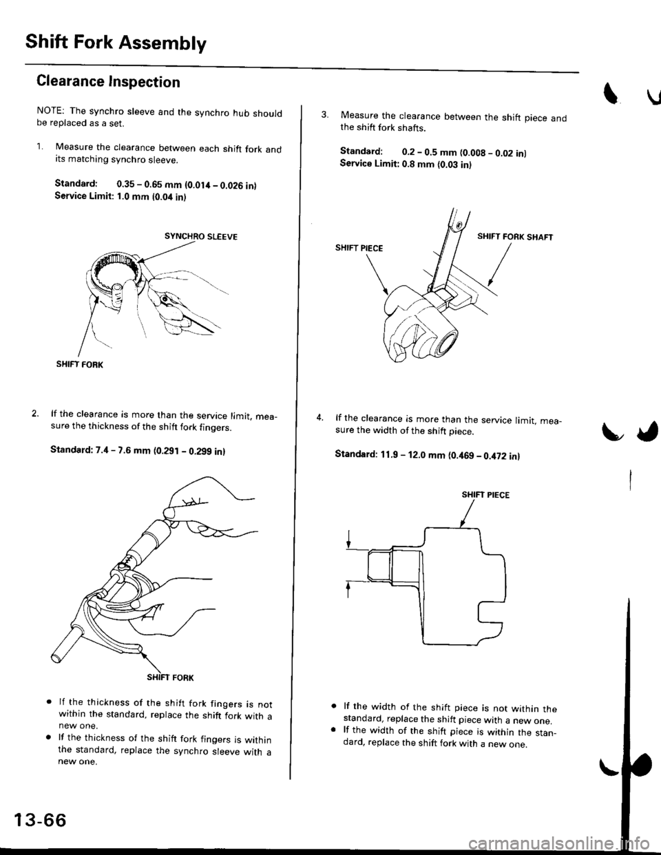
Shift Fork Assembly
Clearance Inspection
NOTE: The synchro sleeve and the synchro hub shouldbe replaced as a set.
1. Measure the clearance between each shift fork andits matching synchro sleeve.
Standard: 0.35 - 0.65 mm {O.Olit - 0.026 inlService Limit: 1.0 mm t0.04 inl
SHIFT FOBK
lf the clearance is more than the service limit. mea_sure the thickness of the shitt fork finoers.
Standard: 7.4 - 7.6 mm (0.291 - 0.299 in)
lf the thickness of the shift fork frngers rs notwithin the standard, replace the shift fork with anew one.
lf the thickness of the shift fork fingers is withinthe standard, replace the synchro sleeve with a
13-66
3. Measure the clearance between the shift piece andthe shift fork shafts.
Standard: 0.2 - 0.5 mm (0.008 - 0.02 inlService Limit: 0.8 mm {0.03 in)
lf the clearance is more than the service limit. mea-sure the width of the shift Diece.
Standard: 11.9 - 12.0 mm (0.469 - 0.it72 in)
lf the width of the shift piece is not within thestandard, replace the shift piece with a new one.lf the width of the shift piece is within the stan_dard, replace the shift fork with a new one.
t,
SHIFT PIECE
Page 660 of 2189
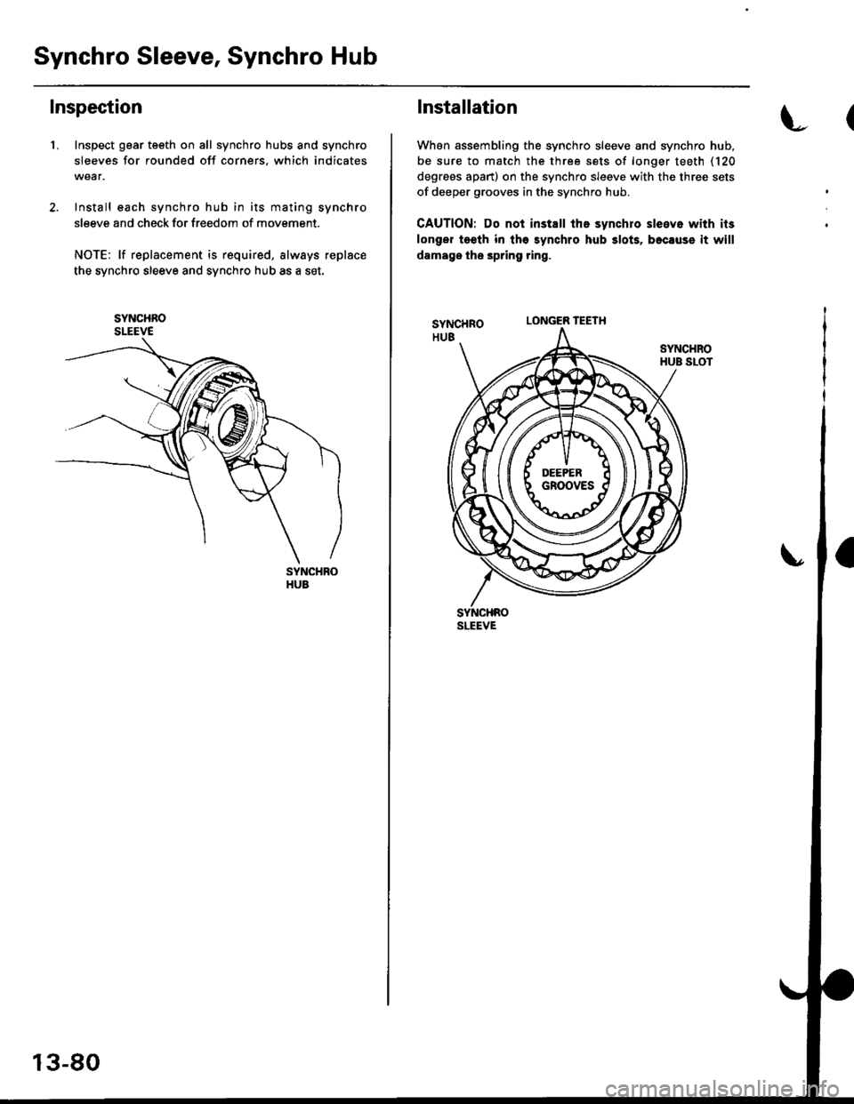
Synchro Sleeve, Synchro Hub
Inspection
1,Inspect gear teeth on all synchro hubs and synchro
sleeves for rounded off corners. which indicates
Install each synchro hub in its mating synchro
sleeve and check for freedom of movement.
NOTE: lf replacement is required, always replace
the synchro sleeve and synchro hub as a set.
Installation
When assembling the synchro sleeve and synchro hub,
be sure to match the three sets of longer teeth (120
degrees apart) on the synchro sleeve with the three sets
of deeper grooves in the synchro hub.
CAUTION: Do noi install tho synchro sleeve with its
longer toeth in the synchro hub slots, because it will
damage the spring ring.
SYNCItROSLEEVCLONGER TEETH
13-80
Page 661 of 2189
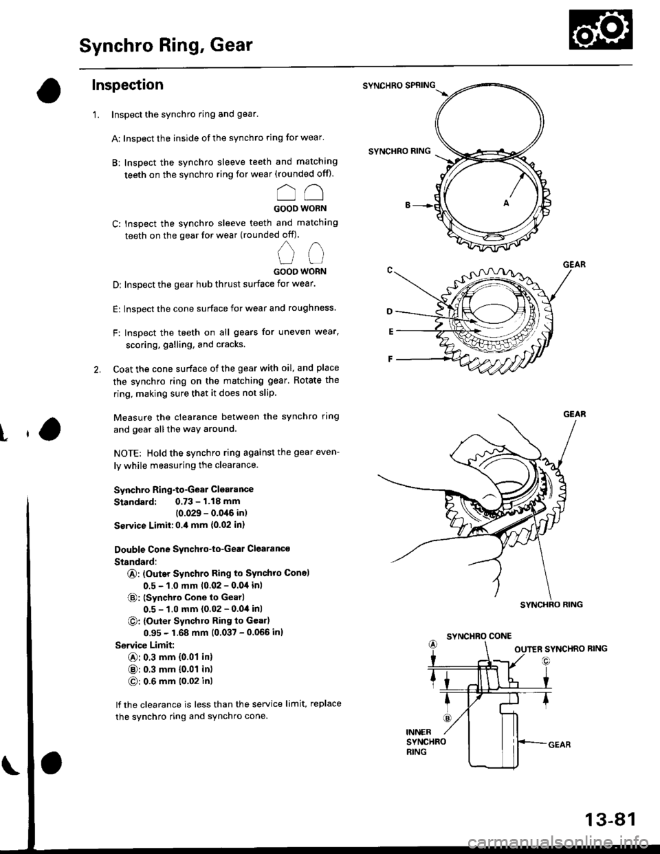
Synchro Ring, Gear
Inspection
'1. Inspect the synchro ring and gear.
A: Inspect the inside of the synchro ring for wear'
B: Inspect the synchro sleeve teeth and matching
teeth on the synchro ring for wear (rounded off).
oo
GOOD WORN
C: Inspect the synchro sleeve teeth and matching
teeth on the gear for wear (rounded off).
nn
UUGOOO WORN
D: Inspect the gear hub thrust surface for wear.
E: Inspect the cone surface for wear and roughness.
F: Inspect the teeth on all gears for uneven wear,
scoring, galling, and cracks'
2. Coat the cone surface of the gear with oil, and place
the synchro ring on the matching gear. Rotate the
ring, making sure that it does not slip
Measure the clearance between the synchro ring
and gear allthe way around.
NOTE: Hold the synchro ring against the gear even-
ly while measuring the clearance.
Synchro Ring-to-Gear Clearance
Standard: 0.73 - 1.18 mm
(0.029 - 0.0'16 in)
Ssrvice Limit:0.,0 mm {0.02 in}
Double Cone Synchro-to-Geal Clearanc€
Standald:
@: (Outer Synchro Ring to Synchro Con6l
0.5 - 1.0 mm 10.02 - 0.04 in)
@: (Synchro cone to Gearl
0.5 - 1.0 mm (0.02 - 0.04 inl
O: {Outer Synchlo Ring to Gear)
0.95 - 1.68 mm (0.037 - 0.066 in)
Service Limit:
@: 0.3 mm {0.01 in}
@: 0.3 mm {0.01 in)
O: 0.6 mm t0'02 inl
lf the clearance is less than the service limit, replace
the synchro ring and sYnchro cone.
SYNCHRO SPRING
SYNCHRO RING
t
SYNCHRO CONE
13-81
Page 664 of 2189
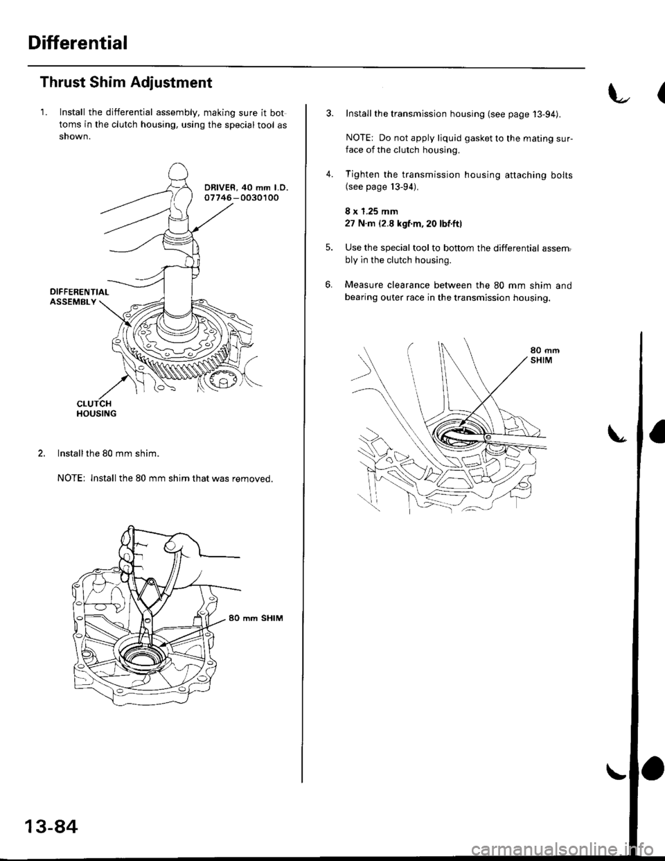
Differential
Thrust Shim Adjustment
1. Install the differential assembly, making sure it bot
toms in the clutch housing, using the special tool as
shown.
ORIVER, 40 mm LO.o7746-0030100
lnstall the 80 mm shim.
NOTE: lnstall the 80 mm shim that was removed.
mm SHIM
13-84
(
4.
Install the transmission housing (see page 13-94).
NOTE: Do not apply liquid gasket to the mating sur-
face of the clutch housing.
Tighten the transmission housing attaching bolts(see page 13-94).
I x 1.25 mm
27 N'm (2.8 kgf.m, 20 lbf.ftl
Use the special tool to bottom the differential assem.
bly in the clutch housing.
Measure clearance between the 80 mm shim and
bearing outer race in the transmission housing.
Page 678 of 2189
Automatic Transmission
Automatic Transmission'.... "'..'.. "...'..' 14-1
Continuously Variable Transmission
(Cy1l .......... 14-193
t
ro
Page 679 of 2189

Automatic Transmission
Special Tools ......... .....'."".'-.-.' 14'2
Description .,....................-...... 14-3
power Flow ......,................. 14"6
Elestronic Control System .... . ................'..'.'.. 14-13
Hvdraulic Control .....'......" 1'l-19
Hydraulic F|ow...... .'.'.".'....11-21
Lock-up System '............ ... t/t'33
Electrical System
Component Locations....,.............'......'.............'.,. 14'39
PCM Circuit Diagram
lA/T Control Syst€m: '96 - 98 Models) .........'.. 1/t-40
PCM Tarminal Volt8ge/Measuring Condhions
{'96 - 98 ModeblA/T Control System ............
PCM Circuit Disgram(A/T Conlrol System: '99 - 00 Modsls) '..........' 14-44
PCM Terminal Voltage/Measuring Conditions('99 - 00 Models)A/T Control System ...
Troubleshooting Proceduros ....
Symptom-to-ComPonent Chari
Efectricaf SFiem - '96 - 98 Models '..-.-..."'.'..11-52
Eloqtrical System -'99 - 00 Modols ... .........". 1+54
EleclricatTroubl$hooting ('96 - 98 Models)
Valve Body
Repair .................... ........'.... 14-139
Valve
Assembly
ATF Pump
1,1-1i10
Inspection ...........'.......... 14-141
Main Valvs Body
Disass€mbf y/lnspoction/R.sssembly .'.'.'.'.. -. -. 1 1-1 12
Secondsry Valve BodY
Disa$embfy/lnspoction/Rsassembly ......'.'.'.'. 11-111
Regulator Valve Body
Disa$embly/lnspoction/Rea3sembly ..........'... 14-1{5
Servo Body
Disassombly/lnsp€ction/Reassembly .".'........ 14-146
Lock-up Valv6 Body
Dis$s.mbf y/ln3poction/Rea$embly .'.. -. -..'.'.' 1 1-1 17
Mainsh!ft
Dkassembly/lnep€ction Reassembly ..'...'........ 14'148
Inspoction .............'..........'. l it-149
Countsrshaft
Disa$embly/lnspeqtion/Rea3sembly .......'...'.. 1a-l51
Dba$ombly/Re$s.mblY11-152
til-46
I rl-48
Troubleshooting Flowcharts
Electrical Troubleshooting ('9!t - 00 Models)
Troublsshooting Flowchart3
Lock-up Control Solenoid vslvo A/B AssemblY
RePlacoment
Shift Cont.ol Solenoid Valve A/B A3sembly
Inspestion
Ona-way Clutch
Disassembh/lrupoction/Rca$embly .. "'........ l4-155
Clutch
lllustlttcd Ind.x {A48A, B4RA Transmlssion) ..' 14-156
tustr.tod Index (MrnA Transmi$ionl ............ til-158
...................... 14-153
L
14-56
1+81'
14-105
1+105
Replacoment ......
Mainshaft/Countorshaft Spo€d Sonsors
Replacemsnt ......'."'........... lit'108
Hydraulic System
Symptom-to-Componeni Chart
Hydraulic Sydemr+109
t4-113
1+116
11-117
Rea$emblY
14-106 Difforrr ial
llhdraied Index........ t4-156
B.ckhrh ln3poction. 14-167
Boaring Roplacemont..-..........11-167
..... 14-108 Diftrrsniial Carrior Repl8cemeni .'.-.............'...' lil-168
Oil Sall Romovalt4-t 59
Oil Soal ln3tallstion/Sidc Clearance'......'.....'... 1'l'169
Torqua Convertcr Housing Boarings
Mlin3haft Besring/Oil Scal Roplac.ment ."..'.. lil-172
Counio6hatt Betring R.plscem.nt ..'...... ....... 14-173
Test.....,......14-106
14-107
14-160
11-162
11-171
11-175
Replacement
Test .....,.,..........
Road Te3t
Linear Solenoid AsssmblY
Stall Speed
lllustrated Indax
Transmission/End Cover'. ....
Transmission Hou3ing,.............'.'......'....""..-.-.. 11-128
Torque Conve.ter Housing/Valvo Body ........... 14-130
End Cover
14-itB Park Stop
1+119 In3pection/Adiustmsnt...'......'.'............'...."""'14-175
Transmbgion
Reassombly
11-122 Torquo Convertet/Drivr Plsie ............'.'............'.. . l4-182
Transmission
11.726 Inrtallation
Tranlmission Housing Boarings
Msinsh.ft /CounteEhaft Bearings
B!pltcomgnt
Rcvo.3s ldlor Gear
lnrtallation
Cooler Flushing ..
Shift Cabls
Test
Fluid Level
Checkin9 .........."..'.'.....
Changing
Pressure Testing
Transmission
Transmission
Rgmoval ..
lil-176
.'..........'.'.'..... 1'l-183
.... lil-187
11-132Adiustmont
RemovaUlnttallation1,1-190
lit-191Transmisgion Housing
Removal ... '.'...... ......'..... 14-l3il
Tolque Convgrter Housing/valvs Body
Rsmoval .........,...... ............. 14-136
Valve CaDs
Description .......'................. t 4'138
Shift lndicator Panel
Adiu3tmant ..'.................. 14-192
ATF Coolor Hoses
Connection ..,............,.,....... l'l-192
Shift Lever .,........