mat HONDA CIVIC 1999 6.G Workshop Manual
[x] Cancel search | Manufacturer: HONDA, Model Year: 1999, Model line: CIVIC, Model: HONDA CIVIC 1999 6.GPages: 2189, PDF Size: 69.39 MB
Page 801 of 2189
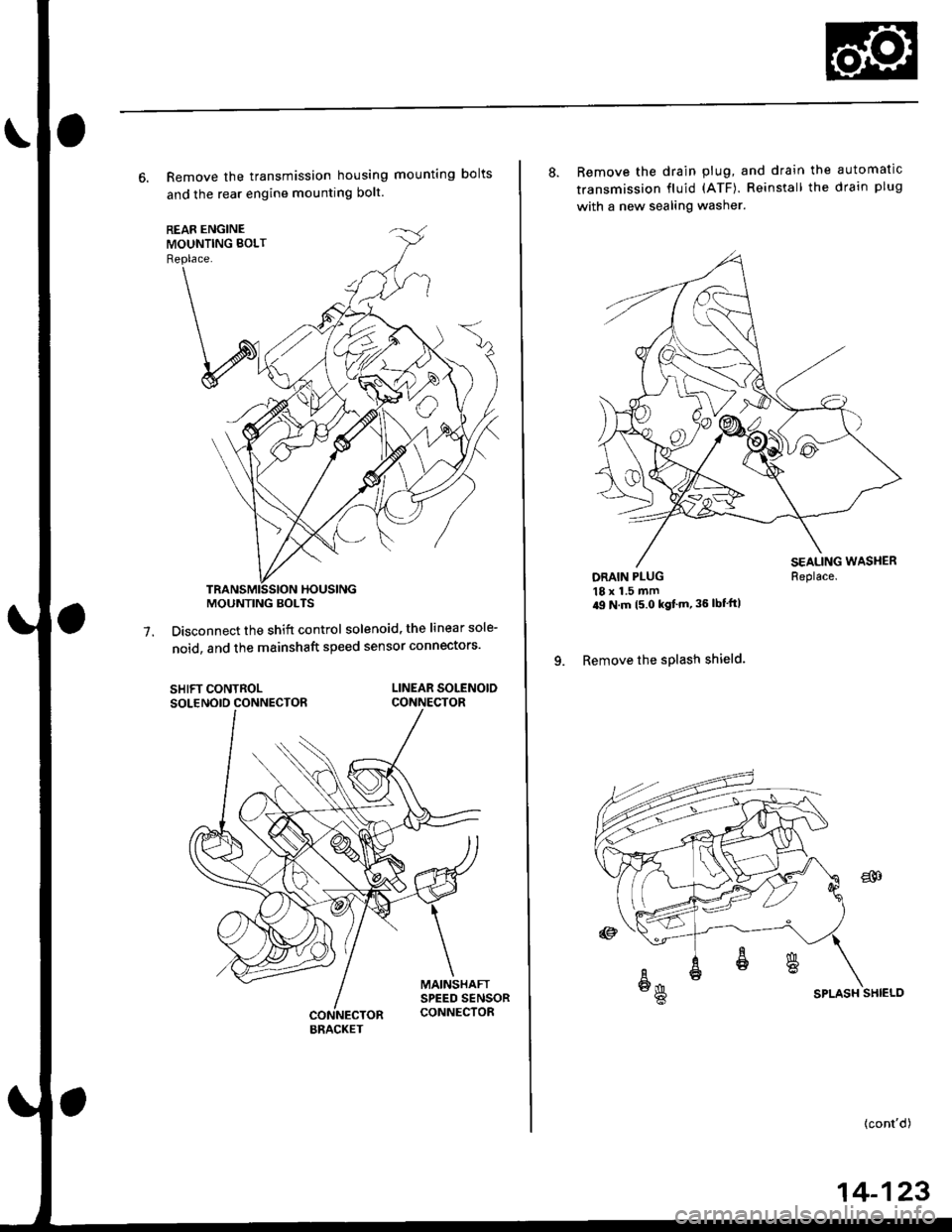
6. Remove the transmission housing mounting bolts
and the rear engine mounting bolt.
Disconnect the shift control solenoid, the linear sole-
noid, and the mainshaft speed sensor connectors'7.
SHIFT CONTROLSOLENOID CONNECTORLINEAR SOLENOIDCONNECTOR
MOUNTING BOLTS
BRACKET
8. Remove the drain plug, and drain the automatic
transmission fluid (ATF). Reinstall the drain plug
with a new sealing washer.
DRAIN PLUG18 x 1.5 mm'9 N m t5 o kgf'm' 36 lbf'ft|
9. Remove the splash shield.
Replace.
SPLASH SHIELD
{cont'd)
14-123
Page 807 of 2189
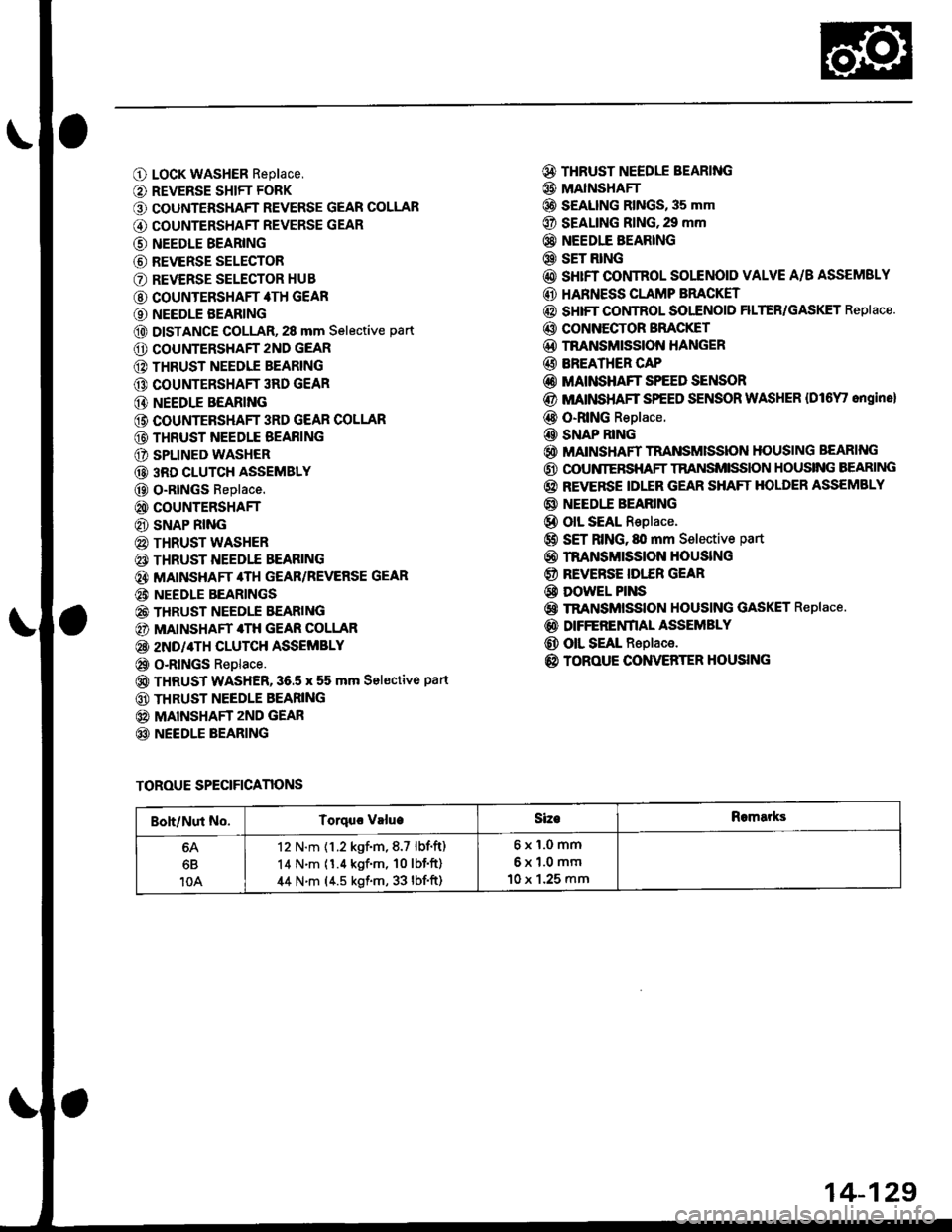
O LocK WASHER Replace,
O REVERSE SHIFT FORK
O COUNTERSHAFT REVERSE GEAR COLLAR
G) COUNTERSHAFT REVERSE GEAR
@ NEEDLE BEARING
@ REVERSE SELECTOR
O REVERSE SELECTOR HUB
@ COUNTERSHAFT 4TH GEAR
O NEEDLE BEARING
@ DISTANCE GOLLAR, 28 mm Selective part
O COUNTERSHAFT 2ND GEAR
@ THRUST NEEDIE BEARING
@ COUNTERSHAFT 3RD GEAR
@ NEEDLE BEARING
@ COUNTEBSHAFT 3RD GEAR COLLAR
@ THRUST NEEDLE BEAFING
O SPLINED WASHER
@ 3RD CLUTCH ASSEMBLY
@ O-RtNGs Replace.
@ COUNTERSHAFT
@ SNAP RING
@ THRUST WASHER
€) THRUST NEEDTE BEARING
@} MATNSHAFT 4TH GEAR/REVERSE GEAR
@i NEEDLE BEARINGS
@ THRUST NEEDLE EEARING
@) MAINSHAFT 4TH GEAR COLLAR
@ 2ND/4TH CLUTCH ASSEMBLY
@ o-RlNGs Replace.
@ THRUST WASHER,36.5 x 55 mm Sel€ctive part
@ THRUST NEEDLE BEARING
@ MAINSHAFT zND GEAR
@ NEEDLE BEARING
@ THRUST NEEDLE BEARING
@ MAINSHAFI
@ S€ALING RINGS, 35 mm
@ SEALING RING,29 mm
@} NEEDIE BEARING
@ SET RING
@ sHrFT CONTROL SOLENOID VALVE A/B ASSEMSLY
@ HARNESS CLAMP BRACKET
@ SHIFT COI,ITROL SOI"ENOID FILTER/GASKET Replace.
@ CONNECTOR BFACKET
@D TNANSMISSION HANGER
@ BREATHER CAP
@ MAINSHAFT SPEED SENSOR
@ MATNSHAFT SPEED SENSOR WASHER {Dl6Y' ongine}
@ O-RING Replace.
@ SNAP RING
@ MAINSHAFT TRANSMISSION HOUSING BEARING
@ OOUNIERSHAFT TRANSMISSION HOUSING BEARING
@ REVERSE IDLER GEAR SHAFT HOLDER ASSEMBLY
@ NEEDI.E BEARING
@ olL SEAL Replace.
@ SET RING, fll mm Selective part
@ rnANsMrssloN HouslNG
@ REVERSE IDI."ER GEAR
@ DowEL PINS
@ TRANSMISSION HOUSING GASKET Replace.
@ DIFFERENfIAL ASSEMBLY
@ OIL SEAL Replace.
@ TOROUE CONVERTER HOUSING
TOROUE SPECIFICANONS
Boh/Nut No.Torquo valueSizeRomarks
6B
10A
12 N.m {1.2 kgf.m,8.7 lbf.ft)
14 N.m (1.4 kgf'm, 10lbf'ft)
44 N.m (4.5 kgf.m, 33 lbf'ft)
6x1.0mm
6x1.0mm
10 x 1.25 mm
14-129
Page 826 of 2189
Mainshaft
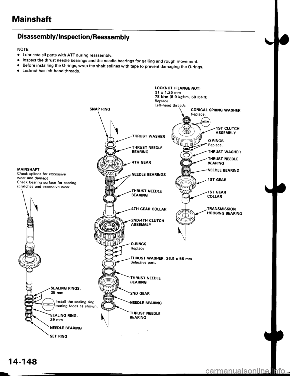
Disassembly/lnspestion/Reassembly
NOTE:
. Lubricate all parts with ATF during reassembly..Inspectthethrustneedlebearingsandtheneedlebearingsforgallingandroughmovement,
. Before installing the O-rings, wrap the shaft splines with tape to prevent damaging the O_rings.. Locknut has left-hand threads.
LOCKNUT {FLANGE NUTI21 x 1.25 mm78 N.m (8.0 kgl.m,58 lbt.fttReplace.Left-hand threadsSNAP RINGCONICAL SPRING WASHERReolace.
lST CLUTCHASSEMBLYTHRUST WASHER
THRUST NEEOI.EBEARING
4TH GEAN
O-RINGSReplace.
THRUST WASHER
THRUST NEEDLEBEARING
MAINSHAFTCheck splines for excessivewear and oamage.Check bearing surtace for scoring,scratches and excessive wear.
BEARINGBEARINGS
THRUST NEEDLEBEABING
4TH GEAR COLLAR
2ND/4TH CLUTCHASSEMBLY
THRUST NEEDLEEEARING
2NO GEAB
NEEDLE BEABING
THRUST NEEDLEBEARING
1ST GEAR
1ST GEARCOLLAR
TRANSMISSIONHOUSING BEARING
O-RINGSReplace.
THRUST WASHER, 36.5 x 55 mmSelective part.
SEALING RINGS,35 mm
Install the sealing ringmating faces as shown,
RING,29 mm
NEEDLE BEARING
SET RING
14-148
Page 865 of 2189
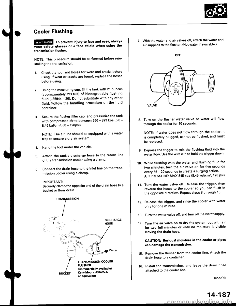
Cooler Flushing
!!!@ To prevent iniury to. face and eyas, always
-ea. safetv glasses ot a face shield when using the
transmission flusher.
NOTE: This procedure should be performed before rein-
stalling the transmission.
1. Check the tool and hoses for wear and cracks before
using. lf wear or cracks are found, replace the hoses
before using.
Using the measuring cup, fill the tank with 2'l ounces
(approximately 2/3 full) of biodegradable flushing
fluid (J35944 - 20). Do not substitute with any other
fluid. Follow the handling procedure on the fluid
contarner.
Secure the flusher filler cap, and pressurize the tank
with compressed air to between 550 - 829 kpa (5 6 -
8.45 kgflcm'�. 80 - 120Psi).
NOTE: The air line should be equipped with a water
trap to ensure a dry air system.
Hang the tool under the vehicle.
Attach the tank's discharge hose to the return line
of the transmission cooler using a clamp.
Connect the drain hose to the inlet line on the trans-
mission cooler using a clamP
IMPORTANT:
Securely clamp the opposite end oJ the drain hose to a
bucket or floor drain.
TRAMtssroN
TRANSMISSION COOLERFLUSHER{Commcrci.llY avail.blel
Kent-Moore J384O5'Aor equivelent
NS
I
{r Water
7. With the water and air valves off, attach the water and
air suDolies to the flusher' lHot water if available.)
8, Turn on the flusher water valve so water will flow
through the cooler for 10 seconds.
NOTE; lf water does not tlow through the cooler, it
is completely plugged. cannot be flushed, and must
be replaced.
9. Depress the trigger to mix the flushing fluid into the
water flow. Use the wire clip to hold the trigger down'
While flushing with the water and flushing fluid for
two minutes, turn the air valve on for five seconds
everv 15 - 20 seconds to create a surging action'
AIR PRESSURE: MAX 845 kpa {8.45 kgf/cm'�, 120 psi)
Turn the water valve off. Release the trigger, then
reverse the hoses to the cooler so you can flush in
the opposite direction. Repeat steps 8 through 10'
12, Release the trigger, and rinse the cooler with water
onlv for one minute
13. Turn the water valve off, and turn off the water supply
14. Turn the air valve on to dry the system out with air
for two full minutes or until no moisture is visible
leaving the drain hose.
CAUTION: Residual mobturo in tho cooler or pipas
can damage the transmksion'
15. Remove the flusher from the cooler line. Attach the
drain hose to a contalner.
16. Install the transmission, and leave the drain hose
attached to the cooler line
{cont'd)
10.
'11.
14-187
Page 866 of 2189
Transmission
17.
Cooler Flushing (cont'dl
Make sure the transmission is in the E position.
Fill the transmission with ATF, and run the enginefor 30 seconds or until approximately 0.95 f (1.0 USqt.,0.8 lmp qt.) is discharged.
Remove the drain hose, and reconnect the coolerreturn hose to the transmission (see page l4-192).
Refill the transmission with ATF to the oroDer level(see page 14-118).
18.
19.
b
14-18A
TOOL MAINTENANCE
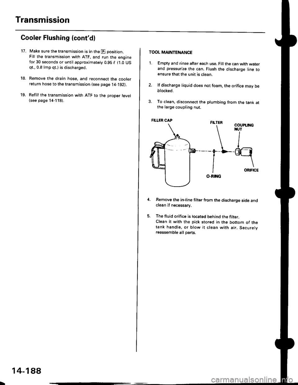
1. Empty and rinse after each use. Fill the can with waterand pressurize the can. Flush the discharge line toensure that the unit is clean.
2. lf discharge liquid does not foam, the orifice may beblocked.
3. To clean, disconnect the plumbing from the tank atthe large coupling nut.
ORIFICE
GRT{G
Remove the in-line filter from the discharge side andclean if necessary.
The fluid orifice is tocated behind the filter.Clean it with the pick stored in the bottom of thetank handle, or blow it clean with air. Securelvreassemble all Darts.
FILLER CAP
Page 868 of 2189
Shift Cable
Adjustment
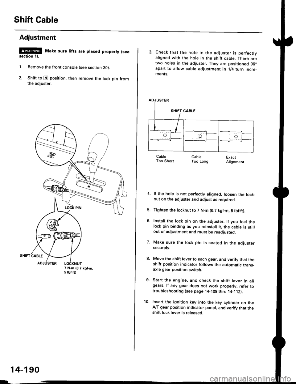
@ Make sure lifts are ptaced properly (see
section 1).
1. Remove the front console (see section Z0l.
2. Shift to @ position. then remove the lock pin fromthe adiuster.
7 N.m (0.75 tbtftlkgtm.
14-190
3. Check that the hole in the adjuster is perfectlyaligned with the hole in the shift cable. There aretwo holes in the adjuster. They are positioned 90.apart to allow cable adjustment in 1/4 turn incre-ments.
ExactAlignment
4. lf the hole is not perfectly aligned, loosen the lock-nut on the adjuster and adjust as required.
5. Tighten the tocknut to 7 N.m (0.7 kgf.m, 5 tbf.ft).
6. Install the lock pin on the adjuster. lf you feel thelock pin binding as you reinstall it, the cable is stillout of adjustment and must be readjusted.
7. Make sure the lock pin is seated in the adjustersecuretv.
8. Move the shift lever to each gear, and verify that theshift position indicator follows the automatic trans-axle gear position switch.
9. Start the engine, and check the shift lever in allgears. lf any gear does not work properly, refer totroubleshooting (see page 14-109 thru 1'4-'112).
10. Insert the ignition key into the key cylinder on theAy'T gear position indicator panel, and verify that theshift lock lever is released.
CableToo ShortCableToo Long
Page 872 of 2189
Special Tools
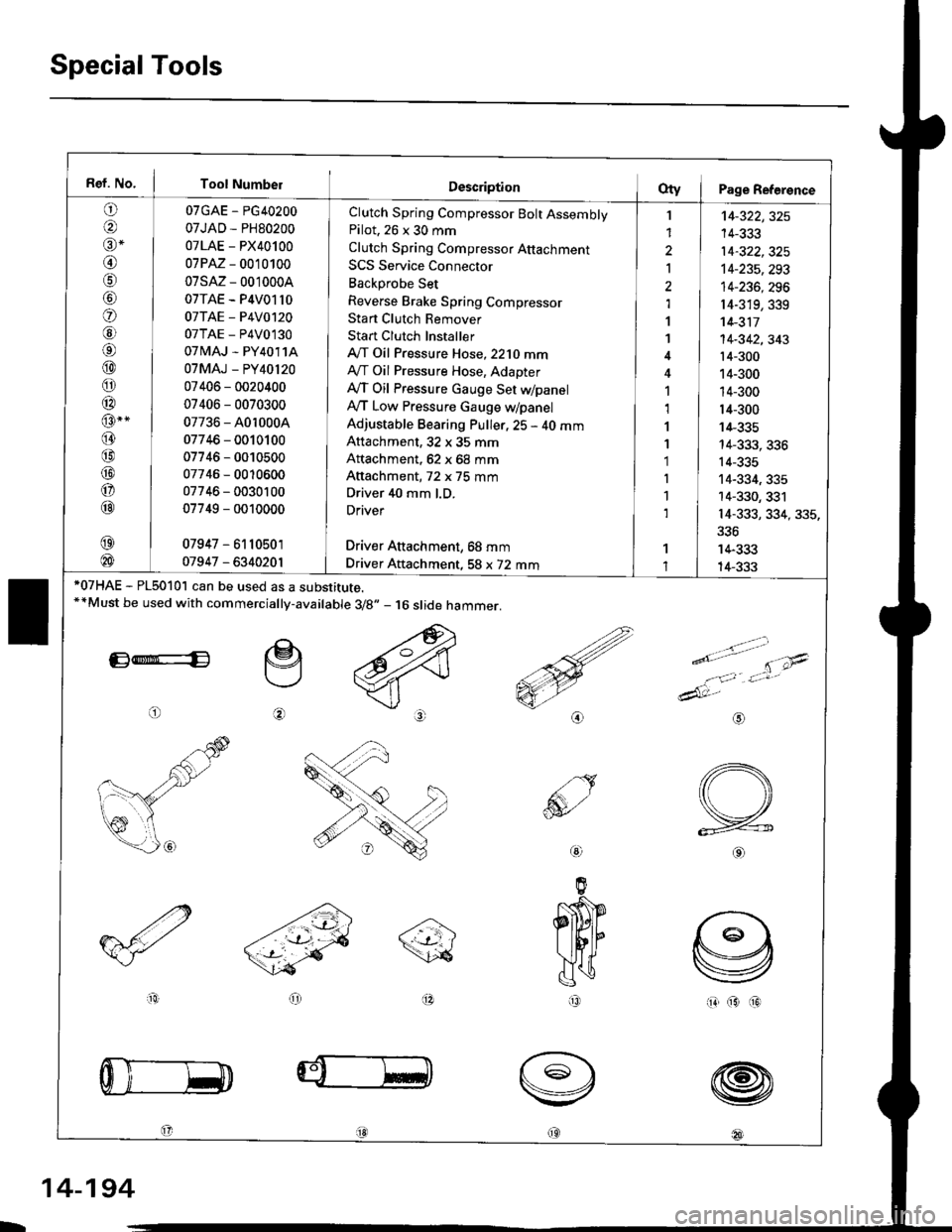
Ref. No. I Tool Number
o
@alr *
@
o
@6l
@
o
@
@-"
@
@
@
o
@
07GAE - PG40200
07JAD - PH80200
07LAE - PX40100
07PM - 0010100
07sM- 0010004
07TAE - P4V01l0
07TAE - P4V0120
07TAE - P4V0130
07 tvlAJ - PY4011A
07MAJ - PY40l20
07406 - 0020400
07406 - 0070300
07736 - A0r 0004
07746 - 0010100
07746 - 0010500
07746 - 0010600
07746 - 0030100
07749 - 0010000
07947 - 6110501
01947 - 6340201
Clutch Spring Compressor Bolt AssemblyPilot. 26 x 30 mm
Clutch Spring Compressor Attachment
SCS Service Connector
Backprobe Set
Reverse Brake Spring Compressor
Stan Clutch Remover
Stan Clutch Installer
A/T Oil Pressure Hose,2210 mmAy'T Oil Pressure Hose, Adapter
Ay'T Oil Pressure cauge Set WpanelAy'T Low Pressure Gauge w/panel
Adjustable Bearing Puller, 25 - 40 mmAttachment, 32 x 35 mm
Attachment, 62 x 68 mm
Attachment, 72 x 75 mm
Driver 40 mm l.D.
Driver
Driver Aftachment, 68 mm
Driver Attachment, 58 x 72 mm
I
1
2
Ia,l
1
1
1,1
1
1'1
I
1
1
't4-322,325
14-333
14-322,325't4-235,293
14-236, 296
r4-319,339't 4-311
14-342,343't4-300
14-300
14-300
14-300
14-335
14-333, 336
14-335
14-334, 335
14-330, 331
14-333, 334, 335,
336
14-333
14-333*07HAE - PL5010l can be used as a substitute.**Must be used with commercially-available 3/8.,- 16 slide hammer.
E*E
o
e
@
>.'.- -t-'- t'\;4
e'o
1:,'Jt*
dAt:-
io(313
@
@
@
@18l
aio
@
IR
L
14-194
Page 873 of 2189
Description
The Continuously Variable Transmission (CVT) is an electronically controlled automatic transmission with drive and driv
en Oullevs, and a steel belt. The CVT provides non stage speeds forward and one reverse. The entire unit is positioned in
line with the engine.
Transmission
Around the outside of the flywheel is a ring gear which meshes with the starter pinion when the engine is being staned.
The transmission has four parallel shafts: the input shaft, the drive pulley shaft. the driven pulley shaft, and the secondary
gear shaft. The input shaft is in line with the engine crankshaft. The drive pulley shaft and the driven pulley shaft consist of
movable and fixed face pulleys. Both pulleys are linked by the steel belt.
The input shaft includes the sun gear. The drive pulley shaft includes the forward clutch which mounts the carrier assem-
bly on the forward clutch drum. The carrier assembly includes the pinion gears which mesh with the sun gear and the ring
gear. The ring gear has a hub-mounted reverse brake disc.
The driven pulley shaft includes the start clutch and the secondary drive gear which is integral with the park gear' The sec-
ondary gear shaft is positioned between the secondary drive gear and the final driven gear. The secondary gear shaft
includes the secondary driven gear which serves to change the rotation direction. because the drive pulley shaft and the
driven oullev shaft rotate the same direction. When certain combinations of planetary gears in the transmission are
engaged by the clutches and the reverse brake, power is transmitted from the drive pulley shaft to the driven pulley shaft
to provide E, E, E, and El.
Electronic Control'96 - 98 Models:
The electronic control system consists of the Transmission Control Module (TCM), sensors, three linear solenoids, and a
inhibitor solenoid. Shifting is electronically controlled under all conditions'
The TCM is located below the dashboard, behind the kick panel on the driver's side.'99 - 00 Models:
The electronic control svstem consists of a Powertrain Control Module (PCM), sensors, three linear solenoids and an
inhibitor solenoid. Shifting is electronically controlled under all conditions. A Grade Logic Control System to control shift-
ing in E position while the vehicle is ascending or descending a slope.
The PCM is located below the dashboard, under the kick panel on the passenger's side.
Hydraulic Control
The lower valve body assembly includes the main valve body, the Pressure Low (PL) reguiator valve body, the shift valve
body, the start clutch control valve body, and the secondary valve body. They are positioned on the lower part of the
transmission housing.
The main valve body contains the Pressure High (PH) control valve, the lubrication valve, and the pitot regulator valve.
The secondary valve body contains the PH regulator valve, the clutch reducing valve, the start clutch valve accumulator,
and the shift inhibitor valve. The PL regulator valve body contains the PL regulator valve and the PH-PL control valve
which is ioined to the PH,PL control linear solenoid. The inhibitor solenoid valve is bolted on the PL regulator valve body.
The shift valve body contains the shift valve and the shift control valve. which is joined to the shift control linear solenoid.
The start clutch control valve body contains the start clutch control valve, which is joined to the start clutch control linear
solenoid. The linear solenoids and the inhibitor solenoid are controlled by the TCM or PCM. The manual valve body which
contains the manual valve and the reverse inhibitor valve, is bolted on the intermediate housing.
The ATF pump assembly is located on the transmission housing, and is linked with the input shaft by the sprockets and
the sprocket chain. The pulleys and the clutch receive fluid from their respective feed pipes, and the reverse brake receives
fluid from internal hydraulic circuit.
Shift Control Mechanism
Input from various sensors located throughout the vehicle determines which linear solenoid the TCM or PCM will activate.
Activating the shift control linear solenoid changes the shift control valve pressure, causing the shift valve to move. This
pressurizes the drive pulley pressure to the drive pulley and the driven pulley pressure to the driven pulley and changes
their effective pulley ratio. Activating the start clutch control linear solenoid moves the start clutch control valve. The start
clutch control valve uncovers the port, providing pressure to the start clutch to engage it(cont'd)
14-195
,!
Page 874 of 2189
Description
(cont'd)
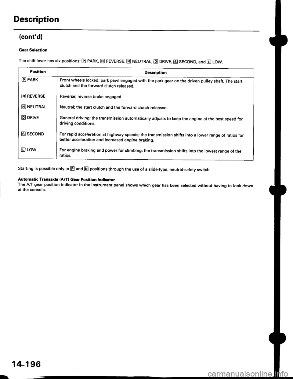
Gear Sel€stion
The shift lever has six positions: @ pARK, E REVERSE, E NEUTRAL, E DR|VE, g SECOND, and El LOW.
Staning is possible only in E and E positions through the use of a slid6-type, neutrafsafety switch.
Automrtic Transaxle {A/T} Gear Position Indicltor
The A-lT gear position indicator in the instrument panel shows which gear has been selected without having to look downat the console.
PoshionDe3cription
E PARK
E REVEBSE
E NEUTRAL
D DRIVE
E SECOND
E LOW
Front wheels locked; park pawl engaged with the park gear on the driven pulley shaft. The startclutch and the forward clutch released.
Reverse; reverse brake engaged.
Neutral; the start clutch and the forward clutch released.
General driving; the transmission automatically adjusts to keep the engine at the best speed fordriving conditions.
For rapid accelsration at highway speeds; the transmission shifts into a lower range of ratios forbetter acceleration and increased engine braking.
For engine braking and power for climbinO; the transmission shifts into the lowest range of theralros.
l-
14-196
Page 889 of 2189
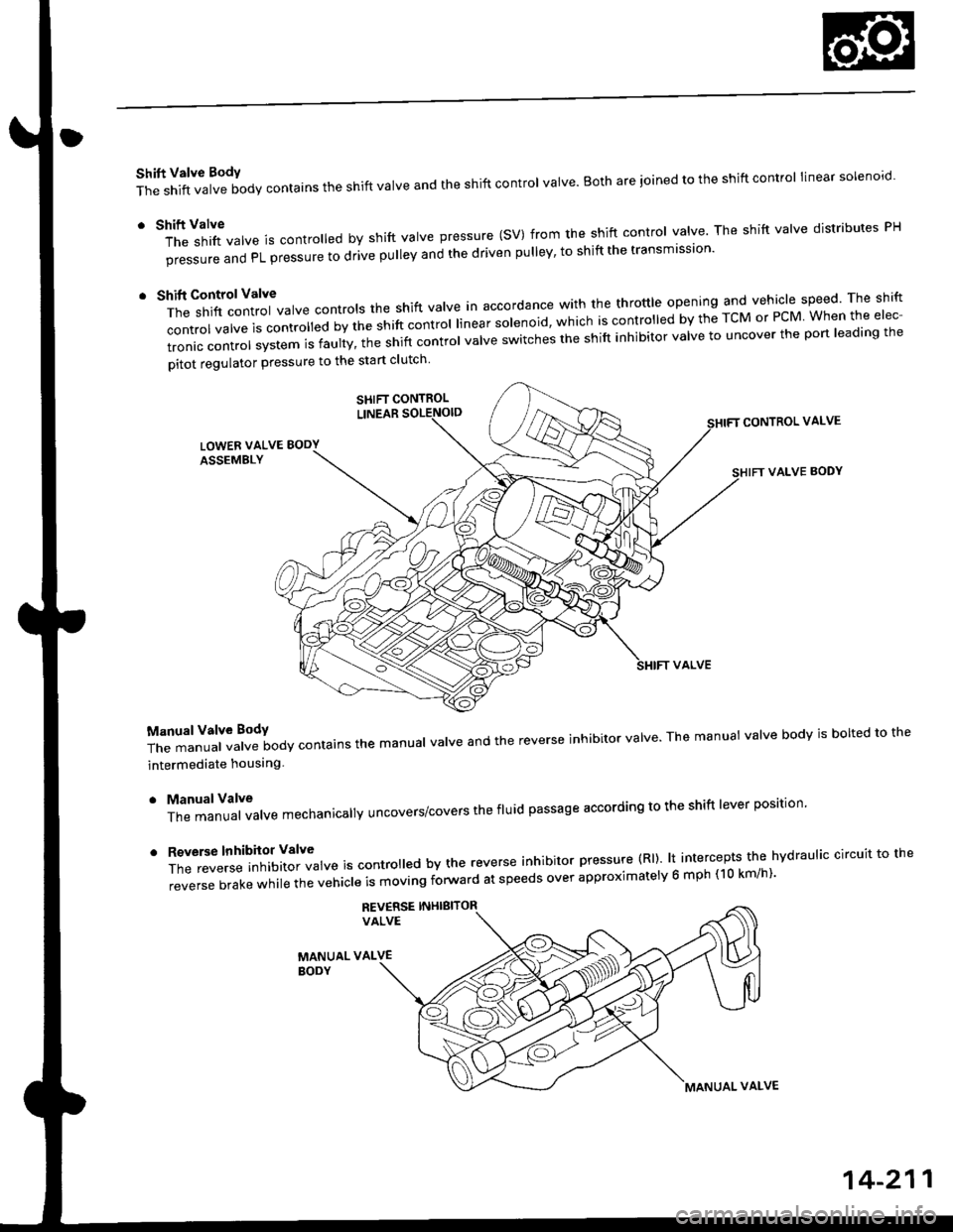
Shift Valve BodY
The shift valve body contains the shift valve and the shift control valve. Both are ioined to the shift control linear solenoro.
r tl'ft1il1rf"","" is controred by shift varve pressure (sV) from the shift contror varve. The shift varve distributes pH
pi""aur" "nO PL pressure to drive pulley and the driven pulley' to shift the transmission'
t t*"rilf:::lr';ivarve contrors the shift varve in accordance with the throttre opening and vehicle speed rhe shift
control valve is convorr"o uv ti" "iirt "ontrol linear solenoid, which is controlled by the TcM or PcM When the elec-
tronic control system is faulty, t;; snift controt uutue "witches the shift inhibitor valve to uncover the port leading the
pitot regulator pressure to the start clutch
CONTROL VALVE
VALVE BODY
T;J:"i"""1ff"t""ilody contains the manuar varve and the reverse inhibitor varve. The manuat varve bodv is borted to the
intermediate houslng
. ManualValve
The manual valve mechanicallY uncovers/covers the fluid passage according to the shift lever position'
'
ff:e;;;.'::'?Xftl::T",* is contro ed by the reverse inhibitor pressure (Rl). lt intercepts the hvdraulic circuit to the
reverse brake while the vehicle is moving forward at speeds over approximatelv 6 mph (10 km/h)'
REV€RSE INHIBITORVALVE
MANUAL VALVEBODY
SHIFT CONTROL
MANUAL VALVE
14-211