troubleshooting HONDA CIVIC 1999 6.G Workshop Manual
[x] Cancel search | Manufacturer: HONDA, Model Year: 1999, Model line: CIVIC, Model: HONDA CIVIC 1999 6.GPages: 2189, PDF Size: 69.39 MB
Page 963 of 2189
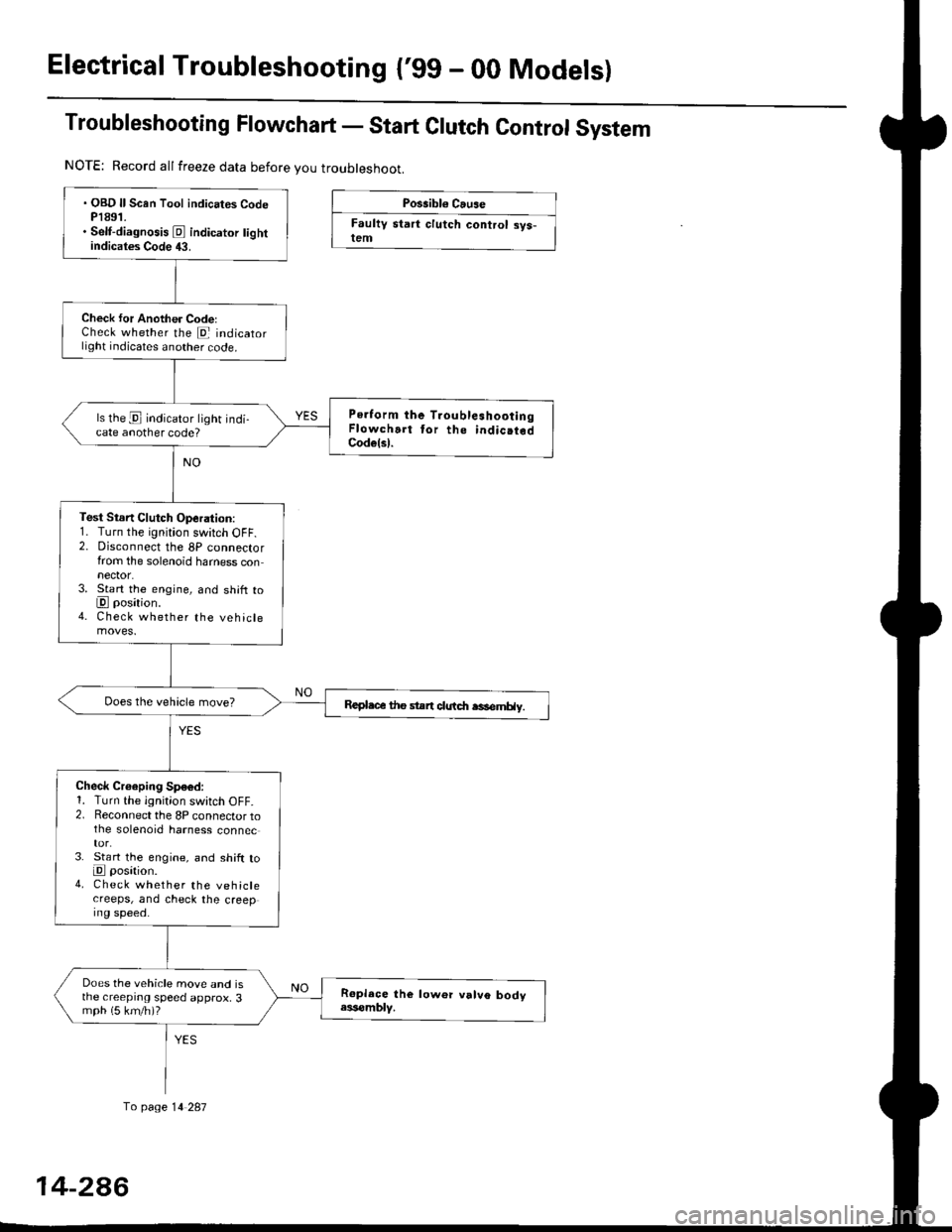
Electrical Troubleshootang ('gg - 00 Models)
Troubleshooting Flowchart - Start Clutch Control System
Possibl€ Cause
Faultv start clutch control sys-lem
NOTE: Record allfreeze data before you troubleshoot.
fo page 14 287
. OBD ll Scan Tool indicates CodeP1891.. Self-diagnosis E indicator tightindicates Code 43.
Check for Another CodelCheck whether the E indicatorlight indicates another code.
Perform the TroubleshootingFlowchart tor the indic.tedCodelsl.
ls the E indicator light indi-cate another code?
Test Stsn Clutch Operation:1. Turn the ignition switch OFF.2. Disconnect the 8P connectorfrom the solenoid harness connector.3. Start the engine, and shift toE position.4. Check whether the vehiclemoves.
Repl.c€ the stan clutdt rasemHy.
Check Croeping Sp€6d:1. Turn the ignition switch OFF.2. Reconnect the 8P connector tothe solenoid harness connec
3. St€rt the engine, and shift toE posation.4. Check whether the vehiclecreeps, and check the creeping speed.
Does the vehicle move and isthe creeprng speed approx, 3mph (5 km/h)?
14-2A6
Page 965 of 2189
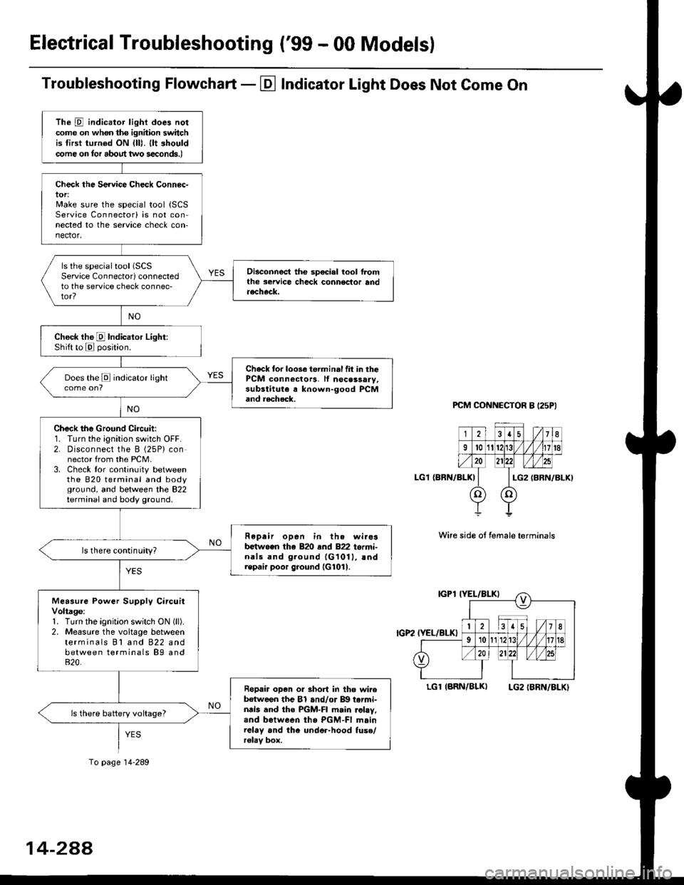
Electrical Troubleshooting ('99 - 00 Models)
Troubleshooting Flowchart - El Indicator Light Does Not Come On
PCM CONNECTOR B I25PI
LGl {BRN/BLK)
Wire side ot female terminals
LGlIARN/BLK) LG2IBRN/BLKI
The D indicator light does notcome on whon ths ignhion switchis tirst turned ON {lll. llt shouldcome on tor about two s€conds.)
Check the Service Check Connec-tor:Make sure the special tool {SCSService Connectorl is not connected to the service check con-nector,
ls the special tool (SCS
Service Connectorl connectedto the service check connec-tor?
Disconnect the sp€cial tool f]omthe seruice chcck connoclor andaecheck.
Check the E Indicalor Light:Shift to E posjtion.
Check tor loose te.minal fit in thePCM connectors, lf nocessary,substitute a known-good PCMand aecheck.
Does the E indicator light
Check the Ground Circuit:1. Turn the ignition switch OFF.2. Disconnect the B (25P) connector from the PCM.3. Check tor continuity betweenthe 820 terminal and bodyground, and between the 822terminal and body ground.
Fepair open in th. wirosb€tw.en the 820 end 822 termi-nals and ground {G1011, !ndrepair poor ground {G1011.
ls there continuity?
Measure Power Supply CircuitVoltage:1. Turn the ignitlon switch ON (ll).
2. Measure the voltage betweenterminals Bl and 822 andbetween terminals B9 and820.
Ropair op€n or short in tho wireb€tween the Bl and/or B!| tarmi-nds and the PGM-FI main .ohy,and between tho PGM-FI mainrelay and the under-hood fuso/r€lav box.
ls there battery voltage?
To page 14-289
14-2AA
Page 967 of 2189
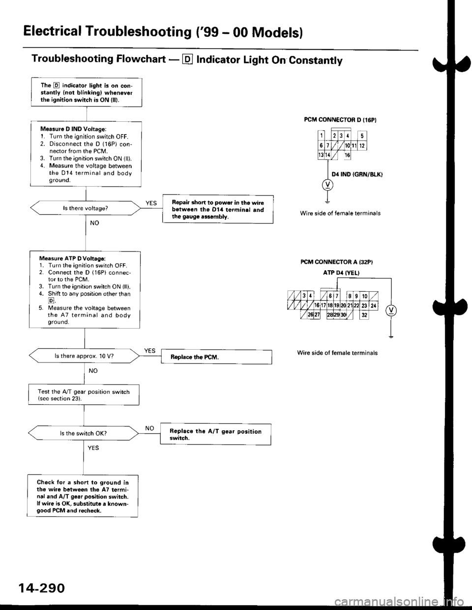
ElectricalTroubleshooting ('gg - 00 Models)
Troubleshooting Flowchart - E Indicator Light On Constantly
FCM CONNCCTOR D tl6PI
23I5
61t012
tsll / rc
II D4 rND
o
(GRN/BLK)
Wire side of female terminals
rcM CONNECTOR A I32PI
ATP Dil {YELI
Wire side of lemale terminals
The E indicator light is on con-stantly {not blinkingl wheneverthe ignition switch is ON lll|.
Mersure D IND Voltage:1. Turn the ignition switch OFF.2. Disconnect the D (16P) con-nector from the PCM.3. Turn the ignition switch ON (ll).4. Measure the voltage betweenthe 014 terminal and bodyground,
Repair short to power in tho wirebstween the Dl4 termin.l sndthe gaug€ r3sembly.
Measure ATP DVoltage:1. Turn the ignition switch OFF.2. Connect the D (16Pi connec-tor to the PCM.3. Turn the ignition switch ON lll).4. Shift to any position other thanE,5. lMeasure the voltage betweenthe 47 terminal and bodyground.
ls there approx. 10 V?
Test the A/T gear position switch{see section 23).
Check for a shorl lo ground inthe wire between tho A7 termi-nal and A/T ge.r polition switch.l, wire is OK, substitute a known-good PCM and recheck.
14-290
Page 977 of 2189
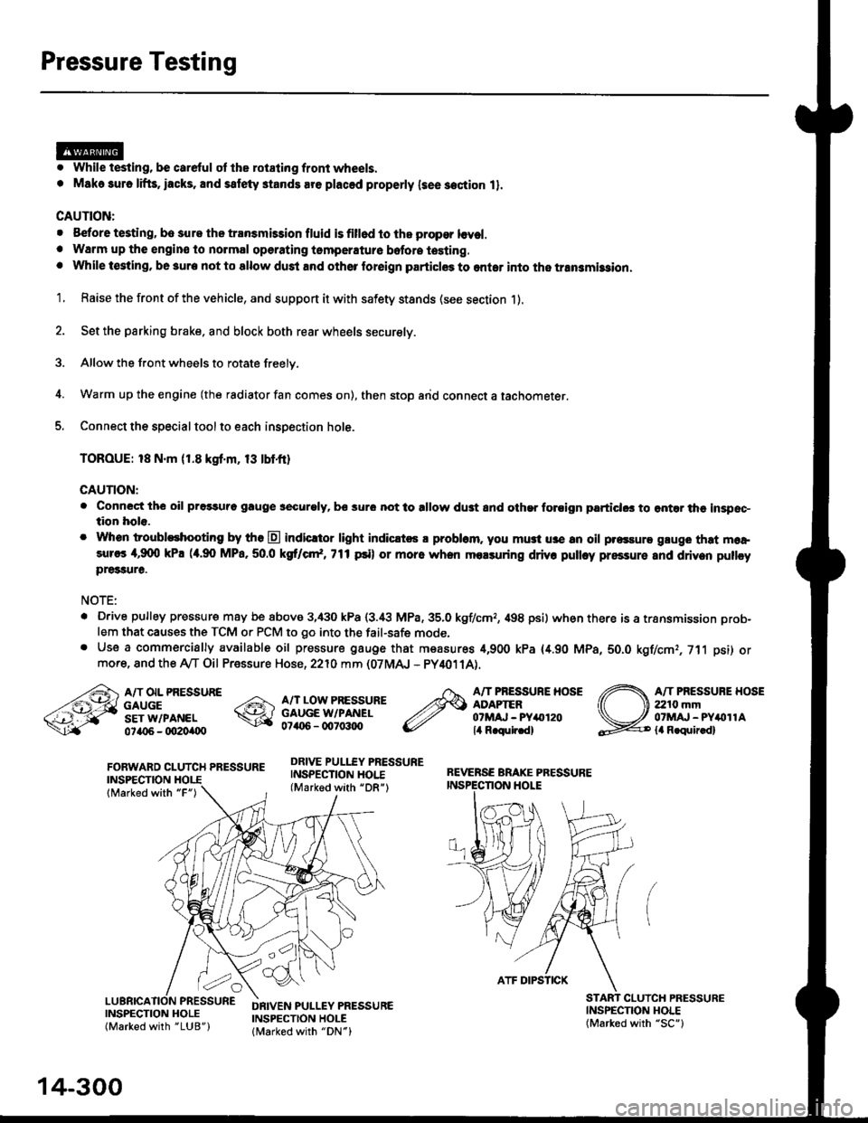
Pressure Testing
. While testing, be careful of the rot8ling front wheels.
. M8k6 suro lifts, iacks, and satety stands are placed properly lsee section 11.
CAUTION:
. Before testing, be sur. the transmb3ion fluid is fillod to the propor lcvel.. Warm up the engin€ to nolmal operating tsmperature bofore testing. While t€sting, be 3ure not to allow dust and other loreign particles to onler into the transmi$ion.
1. Raise the front of the vehicle, and support it with safety stands (see section 1).
2. Set the parking brake. and block both rear wheels securely.
3. Allow the front wheels to rotate freely.
4. Warm up the engine (the radiator fan comes on), then stop arid connect a tachometer.
5. Connect the special tool to each inspection hole.
TOROUE: 18 N.m (1.8 kgt'm, 13 tbtfr)
GAUTION:
. Connect the oil pressuro gauge !!€curoly, bs sur6 not to allow dust and other foroign particlG3 to ontar the inspsc-tion hole.
. Whon troubleshooting by tho E indicltor light indic.t6 a problam. you mu3t u3e an oil p.essure gluge that moa,sures 4,9(X) kPa (a.90 MPa,50.0 kS cr*,771psi) or more when molsuring driv. pulley pressure and driven pullcypre33ure.
NOTE:
. D.ive pulley pressure may be above 3,430 kPa (3.i8 MPa,35.0 kgf/cmr, 498 psi) wh€n there is a transmission prob-
lem that causes the TCM or PCM to go into the fail-safe mode,. Use a commercially available oil pressure gauge that measures 4,900 kPa {4.90 MPa, 5O.O kgf/cmr, 711 psi) ormore, and the Ay'T Oil Pressure Hose, 2210 mm (07MAJ - PY4011A).
FORWARD CLUTCH PRESSUREINSPECTION
lMarked with "F")
REVERSE BRAKE PRESSUREINSPECTION I.IOLE
A/T OIL PRESSUREGAUGESET W/PANEL0ta{r6 - oO2Oi|(Xt
A/T LOW PRESSUREGAUGE W/PANEL0706 - qt7o:t{ro
DRIVE PULLEY PRESSUREINSPECTION HOI.E(Marked with "DR")
A/T PRESSURE HOSEADAPTER07MAJ - PYar'120lil R.qulr.d)
A/T PRESSUBE HOSE2210 mm07MAJ - PYitollAla R.quir.d)
(
INSPECNON HOLE(Marked with "SC")
CLUICH PRESSURE
INSPECTION HOLE(Marked with "LUB")
DRIVEN PULLEY PRESSUREINSPECTION HOLElMarked with "DN")
14-300
ATF DIPSTICK
Page 1031 of 2189
t
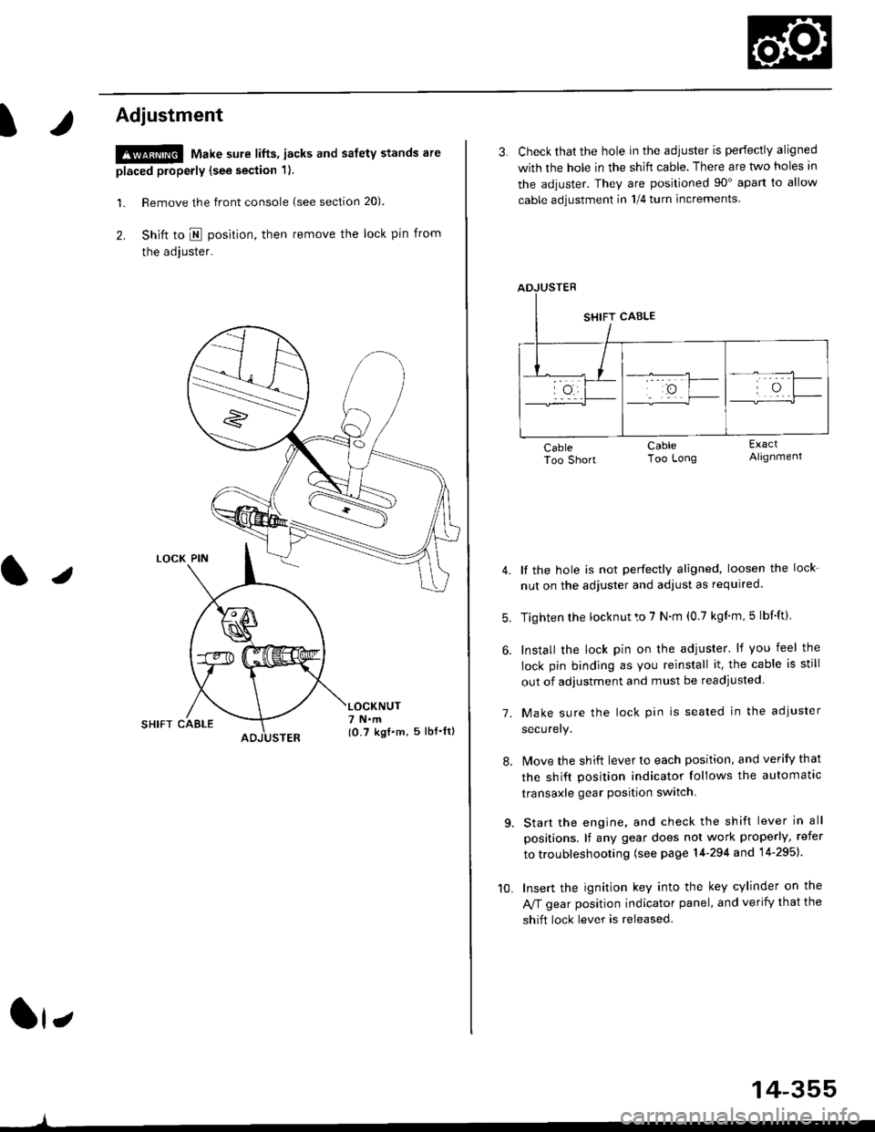
Adjustment
!@ Make sure lifts, jacks and safety stands are
placed properly (see section 1).
l. Remove the front console (see section 20).
2. Shift to I posirion, then remove the lock pin from
the adjuster.
SHIFT CAELE
l,
,l
{0.7 kgf.m, 5lbf'ltl
3. Check that the hole in the adiuster is perfectly aligned
with the hole in the shift cable. There are two holes in
the adjuster. They are positioned 90" apart to allow
cable adjustment in 1/4 turn increments.
lf the hole is not perfectly aligned, loosen the lock-
nut on the adjuster and adjust as required.
Tighten rhe locknut to 7 N.m (0.7 kgim,5 lbf'ft).
Install the lock pin on the adjuster' lf you feel the
lock pin binding as you reinstall it. the cable is still
out of adjustment and must be readjusted
Make sure the lock pin is seated in the adiuster
securery.
lMove the shift lever to each position, and verify that
the shift position indicator follows the automatlc
transaxle gear position switch.
Start the engine, and check the shift lever in all
positions. lf any gear does not work properly, refer
to troubleshooting (see page 14-294 and 14-295).
Insert the ignition key into the key cylinder on the
Aff gear position indicator panel, and verify that the
shift lock lever is released.
7.
10.
14-355
Page 1057 of 2189
l.
t
Steering
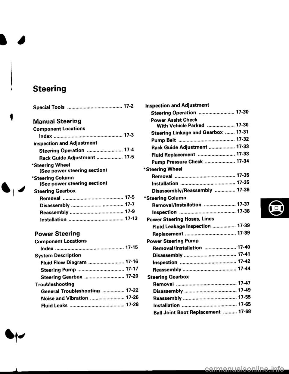
Speciaf Tools ....."'.....17-2
Manual Steering
Component Locations
lndex ................ ....... 17-3
Inspection and Adiustment
Steering Operation "'......"............... 17-4
Rack Guide Adiustment ................... 17-5
*Steering Wheel
(See power steering section)
*Steering Column
(See power steering sectionl
Steering Gearbox
Removal ................. 17-5
Disassembly ......."" 17-7
ReassemblY ..'......... 17-9
lnstallation ............. 17-13
Power Steering
Component Locations
lndex "......."..... """' 17-15
System DescriPtion
Fluid Flow Diagram .........""............. 17'16
Steering Pump ............'... "........"'...-- 17 -17
Steering Gearbox .".................'...'.'.' 17-20
Troubleshooting
Generaf Troubleshooting ..........--.... 17'22
Noise and Vibration ......................... 17 -26
Ffuid Leaks .............17-28
Inspection and Adiustment
Steering Operation'......."'........'...... 1 7-30
Power Assist Check
With Vehicle Parked .."................ 17-30
Steering Linkage and Gearbox ....." 17-31
Pump Beft ...--.""".. 17-32
Rack Guide Adiustment .'.......'.......'. 17'33
Fluid Replacement .....'.."................. 17-33
Pump Pressure Check .............'....-. " 17 -34
'Steering Wheel
Removal .."'........'... 17-35
lnstallation ............. 17-35
Disassembly/Reassembly ......'.....'.' 17-36
*Steering Column
Removal/lnstallation ....'........... ---.... 17'37
lnspection .............. 17'38
Power Steering Hoses, Lines
Fluid Leakage Inspeetion ............'.... 17-39
Replacement ......".. 17-39
Power Steering PumP
Removal/lnstallation .'.'..'..'............. 17-40
Disassembly ".........17-41
fnspection .......---'." 17'42
Reassembly ..'.........17-44
Steering Gearbox
Removal ....'........."' 17'47
DisassemblY ..........' 17-49
Reassembly '........... 17-55
lnstallation ............. 17-65
Ball Joint Boot Replacement .......'.. 17-68
Ir/
lp
Page 1078 of 2189
Troubleshooting
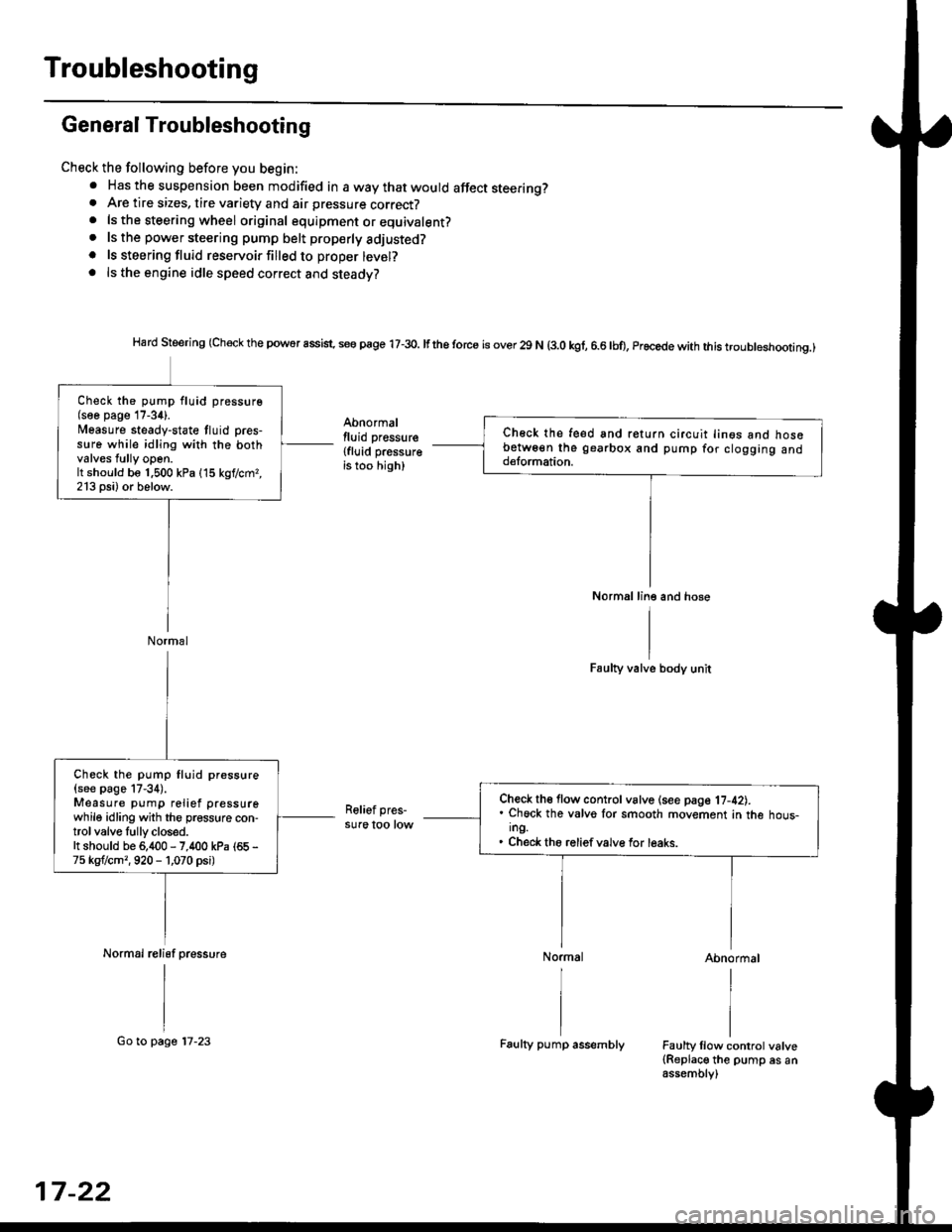
General Troubleshooting
Check the following before you begin:. Has the suspension been modified in a way that would affect steering?. Are tire sizes, tire variety and air pressure correct?. lsthe steering wheel original equipment or equivalent?. lsthe powersteering pump belt properlyadiusted?
. ls steeringfluid reservoirfilledto proper level?. ls the engine idle speed correct and steady?
Hard Steering (Check the powor assist. se€ page 17-3o. lfthe torce is over 29 N (3.0 kgf, 6.6lbo, Procede with this troubleshootinq.)
Abnormallluid pressure
{fluid pressureis too high)
Faulty valve body unit
Relief pres-sure too low
Abnormal
Faulty llow control valve(Replace the pump es anassembly)
Ch€ck the feed snd return circuit lin€s ano nosebetw6€n the gearbox and pump for clogging andd€lormation.
Normal line and hose
Check the pump fluid pressure(soe page 17-34).l/easure steady-state tluid pres-s!re while idling with the bothvalves tully open.It should be 1.500 kPa (15 kgf/cmr,213 psi) or below.
Normal
Check th€ flow control vslve (see page 17-42).. Chock the valvo lor smooth movement in the hous-ing.. Check the reliefvalve for leaks.
Check the pump fluid pressure
{see page 17-34).Measure pump relief pressurewhile idling with the pressure con-trol valve Iully closed.It should be 6,400 - 7,400 kPa (65 -
75 kgflcm,,920 - 1,070 psi)
Normal relisf pressure
17-22
Go to page 17-23Faulty pump assembly
Page 1080 of 2189
Troubleshooting
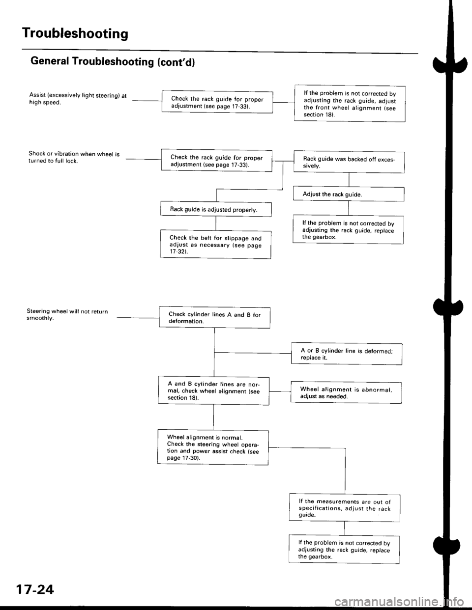
General Troubleshooting (cont'd)
Assist (excessively light steering) athigh speed.
Shock or vibration when wheel isturned to {ull lock.
Steering wheelwill not returnsmoothly.
lf the problem is not corrected byadiusting the rack guide, adjustthe front wheel alignment lseesection 181.
Check the rack guide for properadiustment (see page 17 33).
Check the rack guide for properadjustment (see page 17-33).
Rack guide is adjusted properly.
lfthe problem is not corrected byadjusting the rack guide, replacethe gearbox.Check the belt for slippage andaolust as necessary {see page11 32).
A and B cylinder lines are nor-mal, check wheel alignment (seesection 18).
Wheel alignment is abnormal,adjust as needed.
Wheel alignment is normal.Check the steering wheel opera-tion and power assist check {seepage lT-30).
It the measurements are out ofspecifications, adjust the ra ckguide.
lf the problem is not corrected byadjusting the rack guide, replacethe gearbox.
17-24
Page 1082 of 2189
Troubleshooting
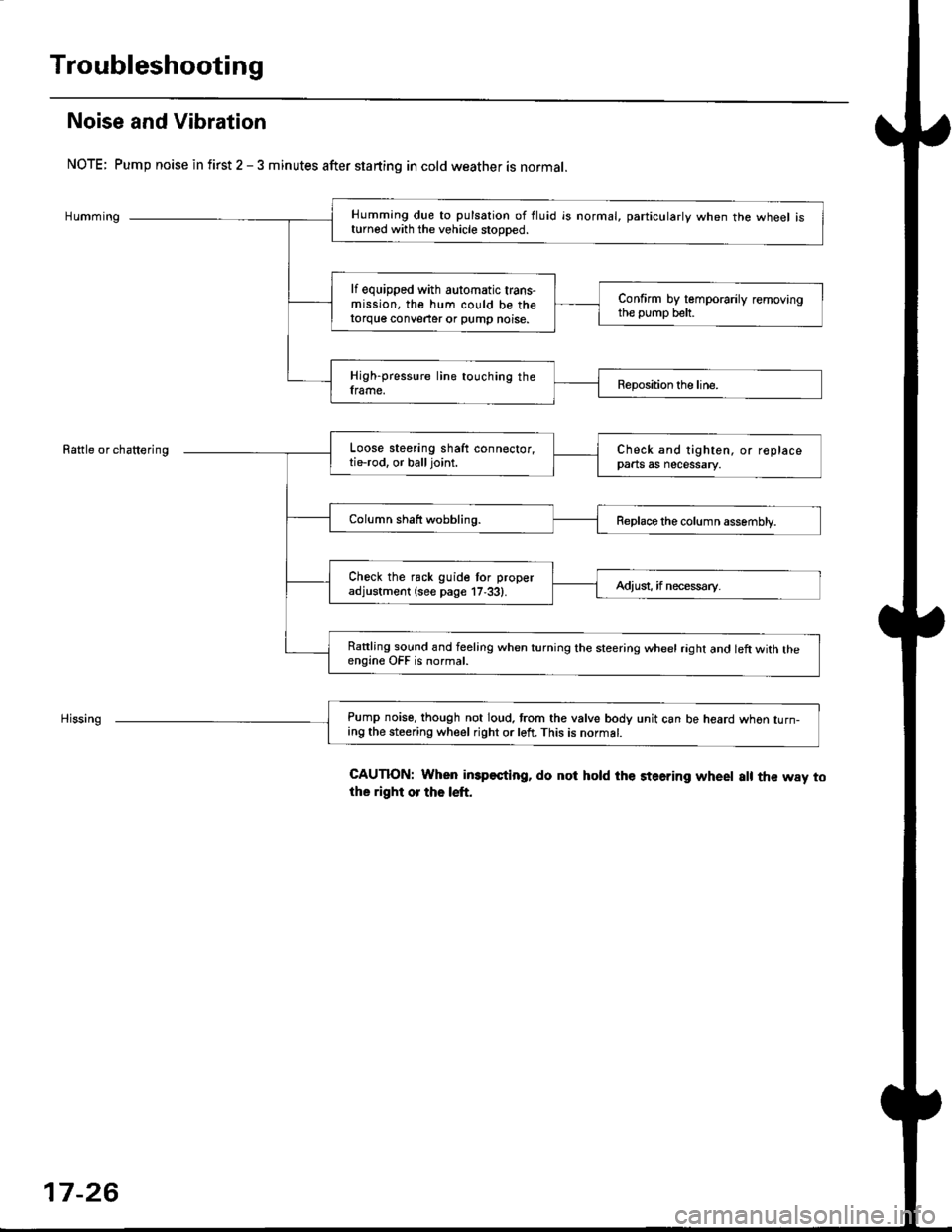
Noise and Vibration
NOTE; Pump noise in first 2 - 3 minutes after starting in cold weather is normal.
Humming
Rattle or chattering
Humming due to pulsation of fluid is normal, particularlv when the wheel isturned with the vehicle stooDed.
lf equipped with automatic trans-mission, the hum could be thetorque conveater or pump noise.
Confirm by temporarily removingthe pump belt.
High-pressure line touching theframe.Reposition the line.
Loose steering shaft connector,tie-rod. or balljoint.Check and tighten, or replacepaats as necessary.
Column shaft wobbling.Replace the column assembly.
Check the rack guide tor properadjustment (see page 17,33).Adiusi, if necess€ry.
Rattling sound and feeling when turning the steering wheel raght and left with theengine OFF is normal.
Pump noise, though not loud. trom the valve body unit can be heard whon turn-ing the steering wheel right or left. This is normat.
CAUTION: When imp€sting, do not hold the steering wheet a[ the way tothe right or the left.
17-26
Page 1084 of 2189
Troubleshooting
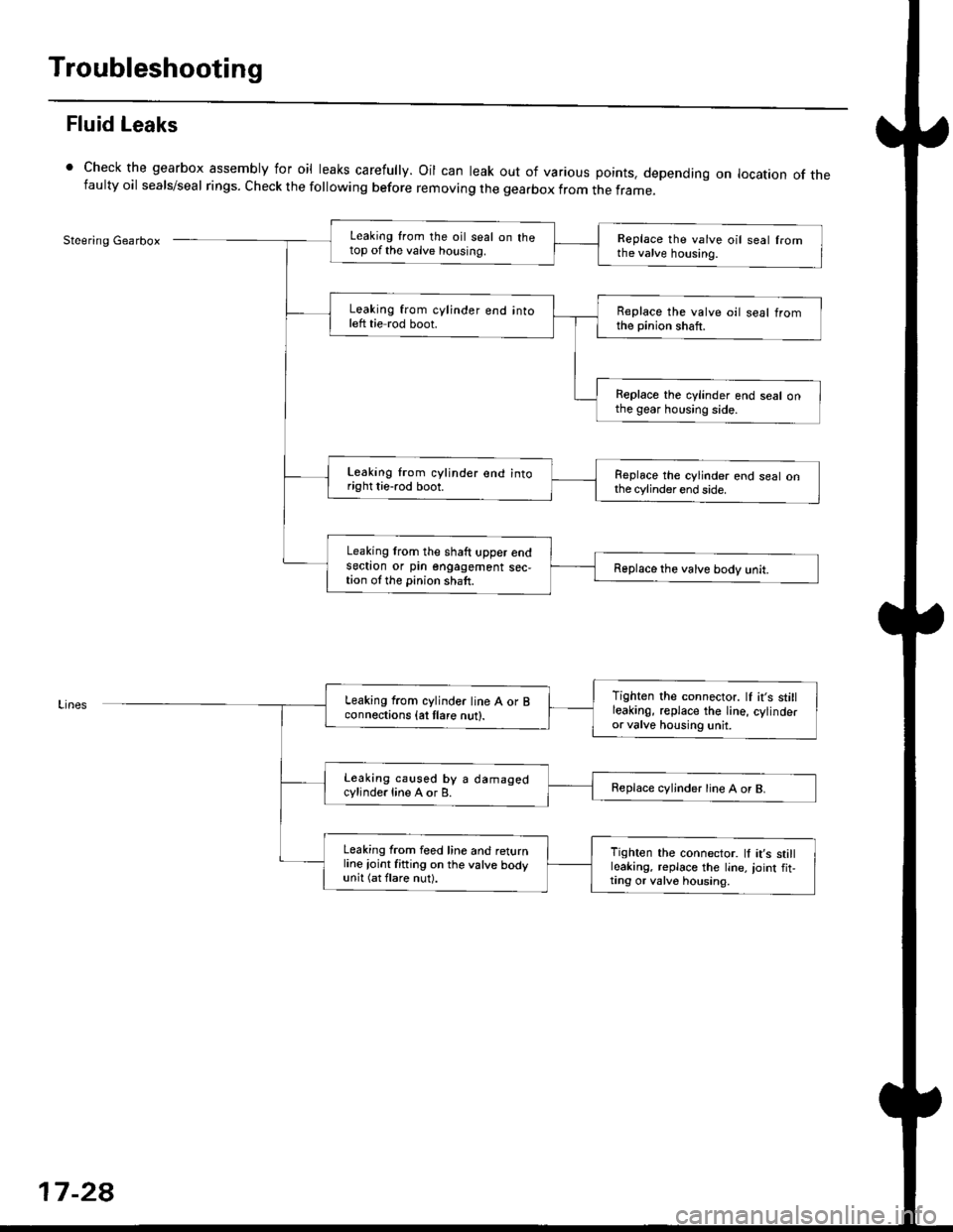
Fluid Leaks
Check the gearbox assembly for oil leaks carefully. Oil can leak out of various points. depending on location of thefaulty oil seals/seal rings. Check the following before removing the gearbox from the frame_
Steering GearboxLeaking from the oil seal on thetop of the valve housing.Replace the valve oil seal fromthe valve housing.
Leaking from cylinder end intoleft tie rod boot.Replace the valve oil seal tromthe pinion shaft.
Replace the cylinder end seal onthe gear housing side.
Leaking lrom cylinder end intoright tie-rod boot.Replace the cylinder end seal onthe cylinder end side.
Leaking lrom the shaft upper endsectron or pin engagement sec,tion ol the pinion shaft.Replace the valve body unit.
Tighten the connector. lf it's stillleakinO, replace the Iine, cylinderor valve housing unit.
Leaking from cylinder line A or Bconnections {at tlare nut}.
Leaking caused by a damagedcylinde.line A or B.Replace cvljnder line A or B.
Leaking from feed line and returnline ioint fitting on the valve bodyunit (at flare nut).
Tighten the connector. ll it's stillleaking, replace the line,,oint fit,ting or valv6 housing.
17-2a