troubleshooting HONDA CIVIC 1999 6.G Workshop Manual
[x] Cancel search | Manufacturer: HONDA, Model Year: 1999, Model line: CIVIC, Model: HONDA CIVIC 1999 6.GPages: 2189, PDF Size: 69.39 MB
Page 1410 of 2189
Troubleshooting -'99 - 00 Models
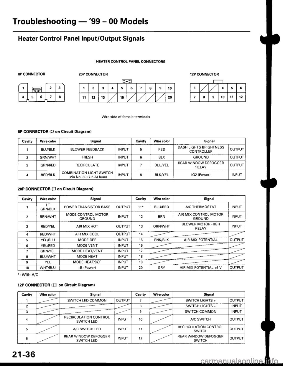
Heater Control Panel Input/Output Signals
HEATER CONTROL PANEL CONNECTORS
8P CONNECTOR2OP CONNECTOR12P CONNECTOR
Wire side of female terminals
8P CONNECTOR (O qn Circuit Diagram)
20P CONNECTOR {D on circuit Diagram}
*: with Ay'c
12P CONNECTOR (tr on Circuit Diagraml
CavityWire colorSignalCavilyWhe colorSignal
BLU/8LKBLOWER FEEDBACKINPUT5REDDASH LIGHTS BRIGHTNESSCONTROLLEROUTPUT
2GRN/lVHTFRESHINPUT6BLKGBOU N DOUTPUT
3GRN/REDRECIRCULATEINPUT7BLU/YELREAR WINDOW DEFOGGERRELAYOUTPUT
4RED/BLKCOMBINATION LIGHT SWITCH(Via No. 30 (7.5 A) fuse)INPUT88LfiELlG2 {Power)INPUT
CavityWire colorSignalCavityWire colorSignal
LTGRN/BLKPOWER TRANSISTOR EASEOUTPUT't1BLU/REDAy'C THERMOSTATINPUT
2BRNMHTMODE CONTROL MOTORGROUNDINPUT12BRNAIR MIX CONTROL MOTORGROU NDINPUT
3RE D/YELAIR MIX HOTOUTPUT13ORNAA/HTBLOWER MOTOR HIGHRELAYINPUT
RED,ryvHIAIR MIX COOLOUTPUT14
5YEUBLUMODE DEFINPUTPN K,/BLKAIR MIX POTENTIALOUTPUT
6YEUREDMODE VENTINPUT16
7GRNI/ELMODE HEAT/r'ENTINPUT11
IBLUAVHTMODE HEATINPUT18
9YELMODE HEAT/DEFINPUT19
10WHT/BLU+B (Power)INPUT20GRYAIR MIX POTENTIAL +5 VOUTPUT
CavityWilecolorSignalCavityWi.e cololSignal
lSWITCH LED COMMONOUTPUT1SWITCH LIGHTS +OUTPUT
2ISWITCH LIGHTS -INPUT
39SWITCH COMMONINPUT
4RECIRCULATION CONTROLSWITCH LEDINPUT10A,/C SWITCHOUTPUT
5A./C SWITCH LEDINPUT11RECIRCULATION CONTROLSWITCHOUTPUT
6REAR WINDOW DEFOGGERSWITCH LEDINPUT12REAR WINDOW DEFOGGEBSWITCHOUTPUT
21-36
Page 1425 of 2189
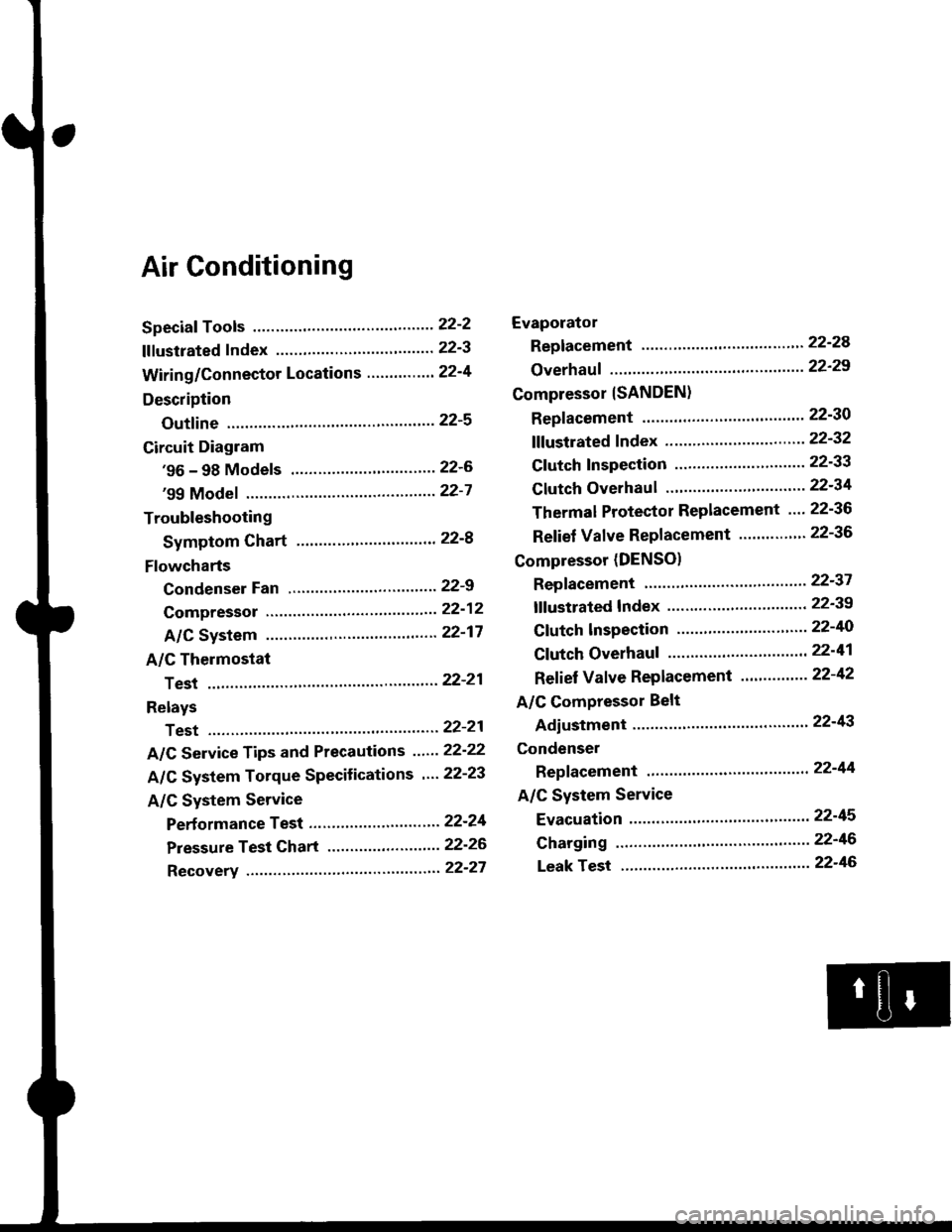
Air Conditioning
Speciaf Tools ......'.....' 22-2
f f f ustrated f ndex ......................... ".......' 22-3
Wiring/Connector Locations'.........'.... 22'4
Description
Outfine ............ .......22-s
Circuit Diagram
'96 - 98 Models ......"..........".......'.... 22-6
'99 Modef """""""' 22-7
Troubleshooting
Symptom Chart ".'......""................. 22-8
Flowcharts
Condenser Fan .........".................,..'. 22-9
Compressor .....""" 22-12
A/C System .........'.22'17
A/C Thermostat
Test ........'.......' """'22'21
Relays
Test ....."'......... ..""'22-21
A/C Service Tips and Precautions ......22-22
A/C System Torque Specifications '...22-23
A/C System Service
Performance Test ... '."......... ".... ....'..22-24
Pressure Test Chart .................. .... "' 22-26
Recovery ...".........," 22-27
Evaporator
Replacement .....",' 22'24
Overhauf .....-.....""' 22'29
Compressor {SANDEN}
Repf acement ......'.' 22-30
fffustrated fndex ......"..................'.... 22'32
Cf utch Inspection ......... "............ ...... 22-33
Clutch Overhau I ........................ ....... 22-34
Thermal Protector Replacement .... 22-36
Relief Valve Replacement ......'..."". 22-36
Compressor (DENSO)
Repfacement ..""',' 22-37
lf lustrated Index ............................... 22-39
Clutch lnspection ............."'...... "'.... 22-40
Cf utch Overhaul .....................'......... 22-41
Ref ief Valve Replacement'..'......"'.. 22-42
A/C Compressor Belt
Adiustment ............22'43
Condenser
Repfacement .......,,22'44
A/C System Service
Evacuation ...,,,.......22-45
Charging '..........--'..22'46
Leak rest """""""'22-46
Page 1432 of 2189
Troubleshooting
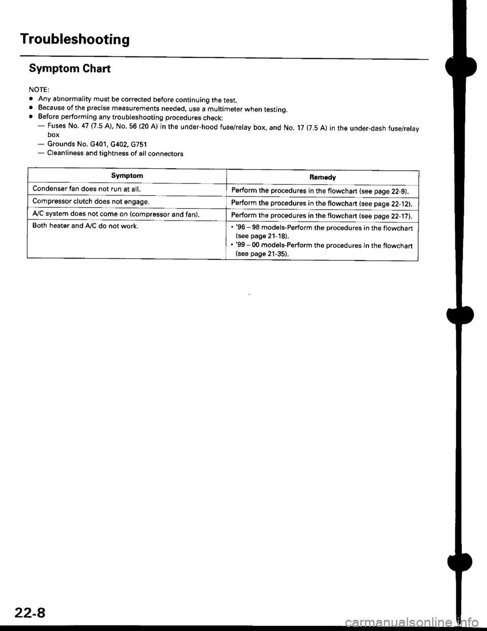
Symptom Chart
NOTE:
. Any abnormality must be corrected before continuing the test.. Because of the precise measurements needed. use a multimeter when testinq.. Before performing any troubleshooting procedures check:- Fuses No. 47 l7 -5 Al, No. 56 (20 A) in the under-hood fuse/relay box, and No. 17 (7.5 A) in the under_dash fuse/relavbox- Grounds No. c401, c402, G751- Cleanliness and tightness of alt connectors
SymptomRemedy
Condenser fan does not run at all.Perform the procedures in the flowchart {see page 22-9).
Compressor clutch does not engage.Perform the procedures in the flowchart lsee page 22-12).
Ay'C system does not come on (compressor and fan),Perform the procedures in the flowchan (see page 22-17).
Both heater and A,/C do not work.. '96 - 98 models-Perform the procedures in the flowchart
{see page 21-18).. '99 - 00 models-Perform the procedures in the flowchart(see page 21-35).
22-8
Page 1434 of 2189
Troubleshooting
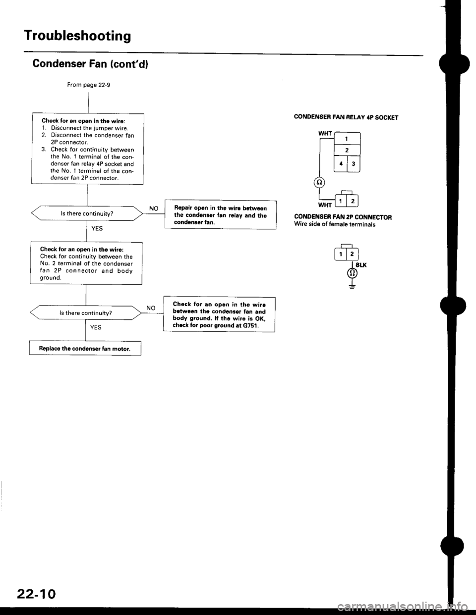
Condenser Fan (cont'd)
CONDENSER FAN RELAY 4P SOCKET
CONDENSEB FAN 2P CONNECTORWire side of female terminals
-=F_
l!.lI slx
@I
Check tor an opon in the wi.o:1. Disconnect the jumper wire.2. oisconnect the condenser tan2P connector.3. Check for continuity betweenthe No. 1 terminal of the con-denser fan relay 4P socket andthe No. 1 terminal of the con-denser fan 2P connector.
Rapair op6n in the wirs bgtwconthe condcnsor tan rclay and thecondgnlar fan.
ls there continuity?
Check to. en open in the wire:Check for continuity between theNo. 2 terminal ot the condenserfan 2P connector and bodyground.
Check Ior rn opon in th6 wirebctwoen the condcnser tan andbody ground, lf iho wirc ii OK,chcck for poor ground at G751.
ls there continuity?
Replaco the condense. fan motor.
22-10
Page 1436 of 2189
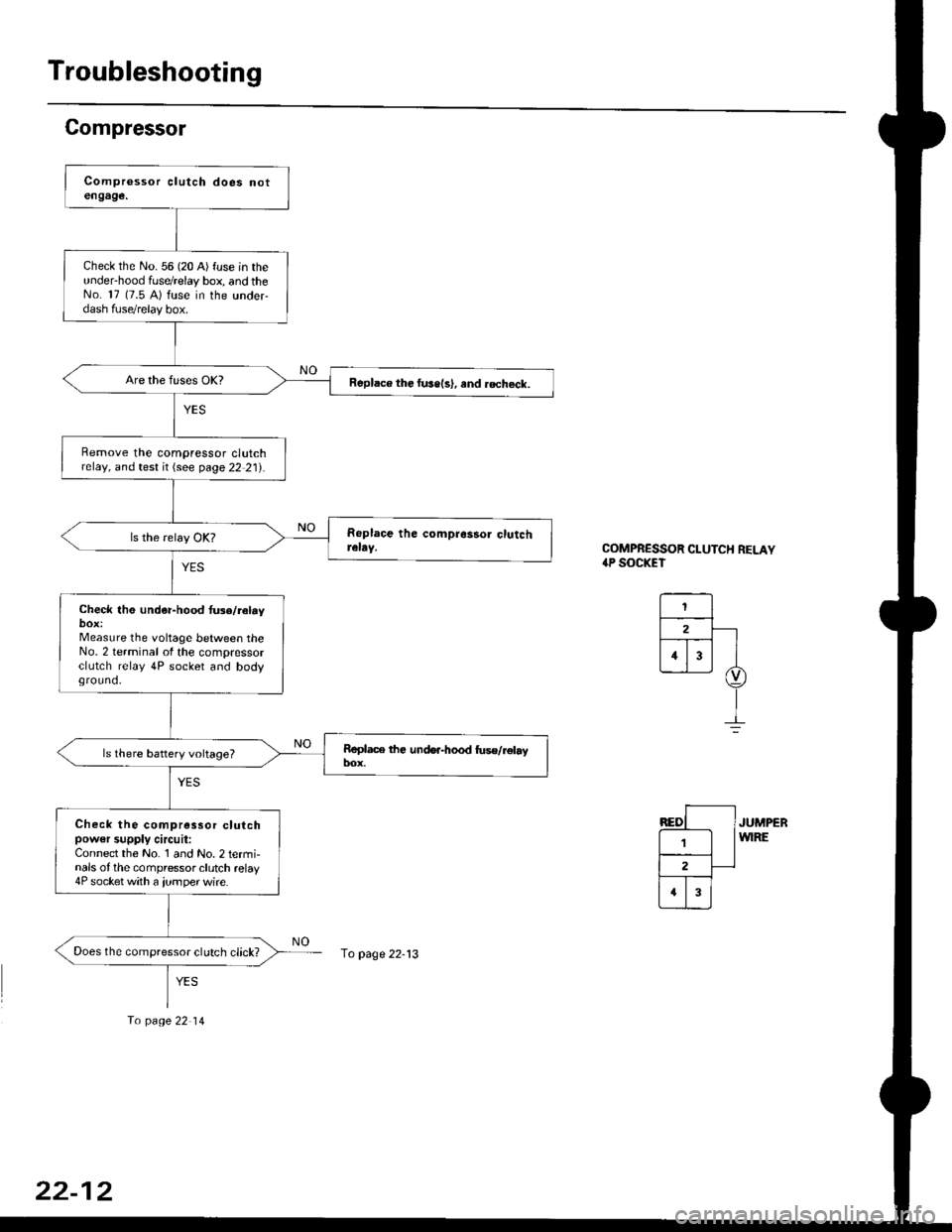
Troubleshooting
Compressor
COMPRESSOR CLUTCH RELAY.P SOCKET
JUMPERWIRE
check the No. 56 (20 A) fuse in theunder'hood fuse/relay box, and theNo. 17 (7.5 A) fuse in the under,dash fuse/relay box.
Replace the fussls), and .echeck.
Remove the compressor clutchrelay, and test it {see page 22 21).
Check th6 und€r-hood tu3e/reby
Measure the voltage between theNo. 2 terminal of the compressorclutch relay 4P socket and bodyground.
Check the compressor clutchpow€r supply circuit:Connect the No. 1 and No. 2 termi-nals of the compressor clutch relay4P socket with a jumper wire.
Does the compressor clutch click?fo page 22-13
To page 22 14
22-12
Page 1438 of 2189
![HONDA CIVIC 1999 6.G Workshop Manual Troubleshooting
Compressor lcontdl
COMPRESSOR CLUTCH RELAY4P SOCKET
l--;l
12 |---r--]l.l3 |L-J--J
] BLK/YEL
A(v)
!
ECM/PCM CONNECTOR A I32P}
Wire side of female terminats
*Howto use the backprobe set HONDA CIVIC 1999 6.G Workshop Manual Troubleshooting
Compressor lcontdl
COMPRESSOR CLUTCH RELAY4P SOCKET
l--;l
12 |---r--]l.l3 |L-J--J
] BLK/YEL
A(v)
!
ECM/PCM CONNECTOR A I32P}
Wire side of female terminats
*Howto use the backprobe set](/img/13/6068/w960_6068-1437.png)
Troubleshooting
Compressor lcont'dl
COMPRESSOR CLUTCH RELAY4P SOCKET
l--;l
12 |---r--]l.l3 |L-J--J
] BLK/YEL
A(v)
!
ECM/PCM CONNECTOR A I32P}
Wire side of female terminats
*Howto use the backprobe setsConnect the backprobe adapters to the stackang patch cords, andconnect the cords to a multimeter. Using the wire insulation as aguide for the contoured tip of the backprobe adapter, gently slidethe tip into the connector from the wire side until it comes in con-tact with the terminalend ofthe wire (see section 11).
Frcm page 22-12
To page 22-15
Check Ior an open in the wire;1. Disconnecl the jumper wire.2. Turn the ignition swatch ON (ll).
3. l\4easure the voltage betweenthe No. 4 terminal of the com-pressor clutch relay 4P socketand body ground.
Repair open in the wire betw€enthe No. 17 fuso and the compres-sor clutch relav.
Check for an open in the wira:1. Turn the ignition switch OFF,then reinstall the compressorclutch relay.2. Make sure the A/C switch isOFF, then turn the ignitionswitch ON (ll).
3. Using a *Backprobe Set (T/N07SAZ 0010004), measurethe voltage between the No.17 terminal oI the ECM/PCMconnector A (32P) and bodyground with the ECM/PCMconnectors connected.
Repair open in the wirc betweonthe compressor clutch relay andthe ECM/PCtvt.
ls there battery voltage?
Page 1440 of 2189
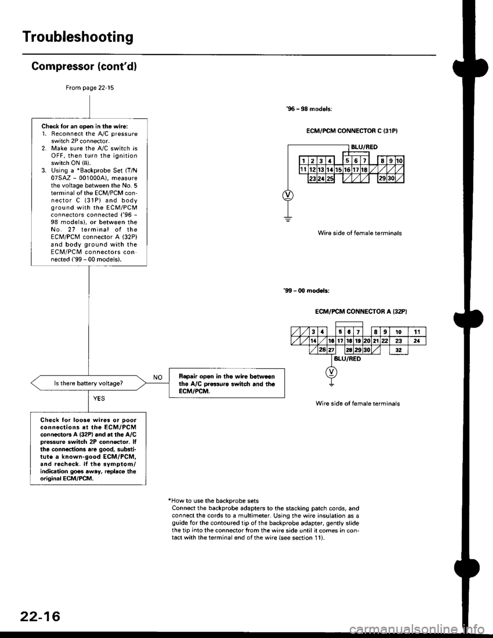
Troubleshooting
Gompressor (cont'dl
'96 -98 models:
ECM/PCM CONNECTOR C 13lPI
Wire side ot female terminals
'9!t - 00 mod.bi
ECM/PCM CONNECTOR A I32P)
Wire side ot female terminals
*How to use the backprobe setsConnect the backprobe adapters to the stacking patch cords, andconnect the cords to a multimeter. Using the wire insulation as aguide for the contoured tip of the backprobe adapter, gently slidethe tip into the connector from the wire side until it comes in con-tact with the terminal end ofthe wire {see section 11}.
From page 22-15
Check for an open in thg wire:'1. Reconnect the A"/C pressure
switch 2P connector.2. Make sure the A/C switch isOFF, then turn the ignitionswitch ON (ll).
3. Using a *Backprobe Set {T/N07SAZ - 001000A), measurethe voltage between the No. 5terminal of the ECM/PCM con-nector C (31P) and bodyground with the EcM/PcMconnectors connected ('96 -
98 models), or between theNo. 27 terminal of theECM/PCM connector A (32P)
and body ground with theECM/PCM connectors connected ('99 - 00 models).
Rapdir open in tho wi?e botwaonthe A/C pr..-ruro lwitch rnd th.ECM/PCM.
Check lor loo3e wires or ooolconnections at the ECM/PCMconnectoB A l32P) and at the A/Cpressure switch 2P connector, lfthe connections are good, substi-tute a known-good ECM/PCM,and recheck. lf the svmptom/indication goos away, repbce theoriginal ECM/PCM.
31501E91011
tat6l11E1921222321
BLU/RED
22-16
Page 1442 of 2189
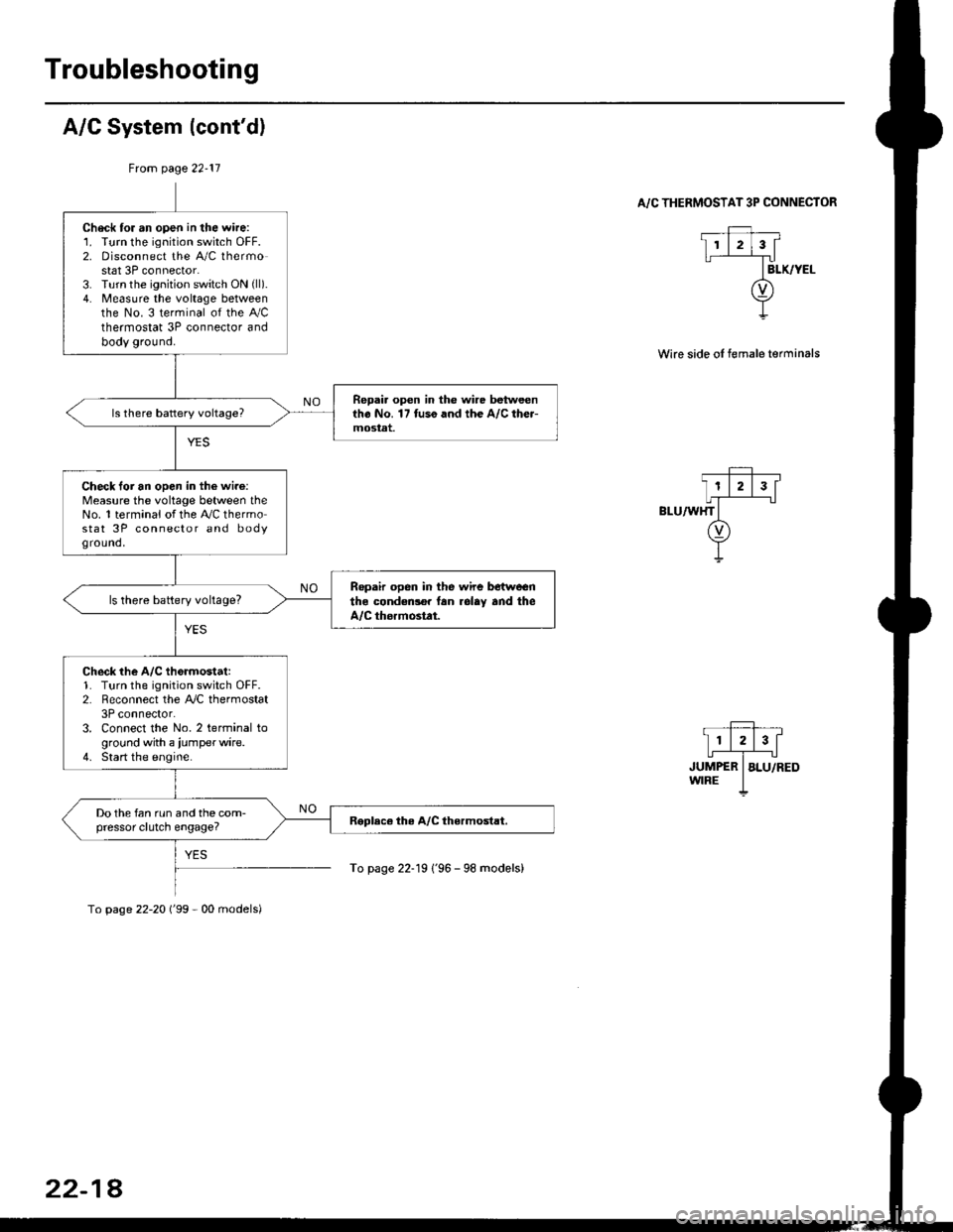
Troubleshooting
A/C System (cont'd)
From page 22-11
. _Ff,, __
I11213[
,r,il*"-T",-.r-'..owrRE I
To page 22-19 1'96 - 98 models)
A/C THERMOSTAT 3P CONNECTOR
Wire side oI female terminals
Check tor an open in the wire:1. Turn the ignition switch OFF.2. Disconnect the A/C thermostat 3P connector.3. Turn the ignition switch ON (ll).
4. Measure the voltage betweenthe No. 3 terminal of the Ay'Cthermostat 3P connector andbody ground.
Repai. open in the wire betweentho No. 17 tuso and the A/C the.-mostat.
Check loi an open in the wi.e:Measure the voltage between theNo. 1 terminal of the A,/C thermostat 3P connector and bodyground,
Ropair open in the wire betwoenthe condedlo. lan rolay and theA/C thormostat.
ls there battery voltage?
Check the A/C th6rmostat:1. Turn the ignition switch OFF.2. Reconnect the A,/C thermostat3P connector.3. Connect the No. 2 terminal toground with a iumperwire.4. Start the engine.
Do the fan run and the com-pressor clutch engage?
To page 22-20 ('99 - 00 models)
22-18
Page 1444 of 2189
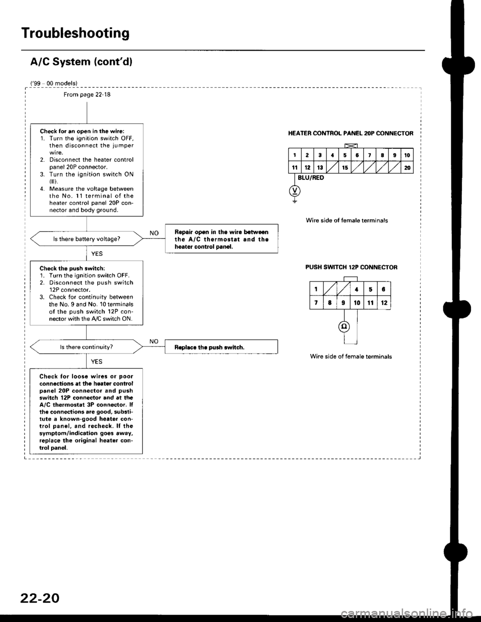
Troubleshooting
('99 00 models)
From page 22 18
Check lor an open in the wire:1. Turn the ignition switch OFF,then disconnect the ju mper
2. Disconnect the heater controlpanel 20P connector.3. Turn the ;gnition switch ON{
i.4. Measure the voltage betweenthe No. 11 terminal of theheater control panel 20P con-nector and body ground.
Ropai. opan in tho wira batwaonthe A/C thermostat and thehoater control oanol.ls there battery voltage?
Check the push switch:1. Turn the ignition switch OFF.2. Disconnect the push switch12P connector.3. Check for continuity betweenthe No. I and No. 10 terminalsof the push switch 12P con-nector with the A/C switch ON.
Check for loose wi.es or poor
connections el the hgater controlpanel 20P connector and pushswitch 12P connector and at theA/C thermostat 3P connector. Ittha connections are good, substi-tute a known-good heatea con-trol pan€|, and recheck. lf thesymptom/indication goe3 away,replace lhe original healer con-trol oan€|,
HEATER CONTROL PANEL anP CONNECTOR
Wire side of temale terminals
PUSH SW]TCH 12P CONNECTOR
Wire side of female terminals
,/1,/156
7819t01112
I
I
I
Page 1471 of 2189

l'f .
Electrical
Special Toofs .,....................,23-2
Troubleshooting
Tips and Precautions ..............,.................... . 23-3
Five-step Troubleshooting .............. ......... . . 23-5
wire color codes ..........,23-5
Schematic Symbols ........,................... . . .. .... 23-6
Relay and Control Unit Locations
Engine Compartment ...,..................... ... .. . 23'7
Dashboard ......................23-8
Dashboard/Door ......... 23-12*Airbags ................. ....... Section 24
Air Conditioning ......... Section 21
Aftelnator ..........."""" """ 23-112
Anti-lock Brake System {ABS) Section 19*A/T Gear Position Indicator .....................,. .... ... 23-149
Automatic Transmission Svstem .... . ....... Section 14
Batterv ......... . . . ... ...... .......23-91
Blower controls .. . ... Section 2l
Charging System ....'...........23'112
Connector ldentilication and Wire Harness
Routing .................. ......23'13
Cruise Control ............,........23-240
Dash Lights Brightness Controller ............. ....... 23-180
Fan controfs "" 23'126
Fuel PumD ........ . ........ section 11
Fuses/Refay ...............,..,,.. 23'62
PGM-FI Control System ......................,....... Section 1 1
*Gauges
Circuit Diagram ....,.,.......23-131
Fuef Gauge ...........'.'.......23-142
Gauge/lndicator .. . .. 23-129
Ground Distribution .. . 23-75
Heatei controls .. . ..... Section 21*Horn................. ...............23-196
*tgnition Switch ....................23-89
lgnition System .......,.... 23-102
*lntegrated Control Unit ....................................... 23-156
fnterlock System ,........ . . , ,23-144
Lighting System . . . .. ......... 23-161
Lights, Exterior
Back-up Lights ..'............23'171
Brake Lights .................. 23'174
Daytime Bunning Lights (Canadal ............... 23'166
Front Parking Lights ......,................ .'. .......... 23-167
Front Turn Signal Lights .......... . . ............ ..,.23-167
Headtights ....".'....-... ..... 23'167
High Mount Brake Light ...................... ... .23'179
License Plate Lights ...... 23'176
Taitfights ................ .......23'171
lnterior Lights ..-.......,, . 23-142
Moonroof ..,.................,........ 23-235
Power Distribution ....... . . .23-61
Power Door Locks .......,,,. .23'251
Power Mirrors ,..............,.,...23'206
Power Relays ....... . ...... . . .. 23-86
Power Windows ............,,....23-220
Rear Window Defogger .......................... . . ... . . 23-2OO
Spark Plugs . ..... . ........ .....23-111
Slarting System ................23-93*stereo Sound Svstem ,................. ..... ... . ... ,.,.,,23'147'Supplemental Restraint System (SRS) ... . Section 24
Turn Signal/Hazard Flasher System .......'.'....-... 23-173
*Undel-dash Fuse/Relay Box ............,.................. 23-85
vehicfe soeed sensor (VSSI """" ""' 23-140+Wipers/Washers .........,.,.,...23-214
NOTE: Unless otherwise specified, references to auto-
matic transmission (Mf) in this section include the CVT.