Fuel HONDA CIVIC 1999 6.G Workshop Manual
[x] Cancel search | Manufacturer: HONDA, Model Year: 1999, Model line: CIVIC, Model: HONDA CIVIC 1999 6.GPages: 2189, PDF Size: 69.39 MB
Page 565 of 2189
Emission Gontrol System
Evaporative Emission (EVAP) Controls (cont'dl
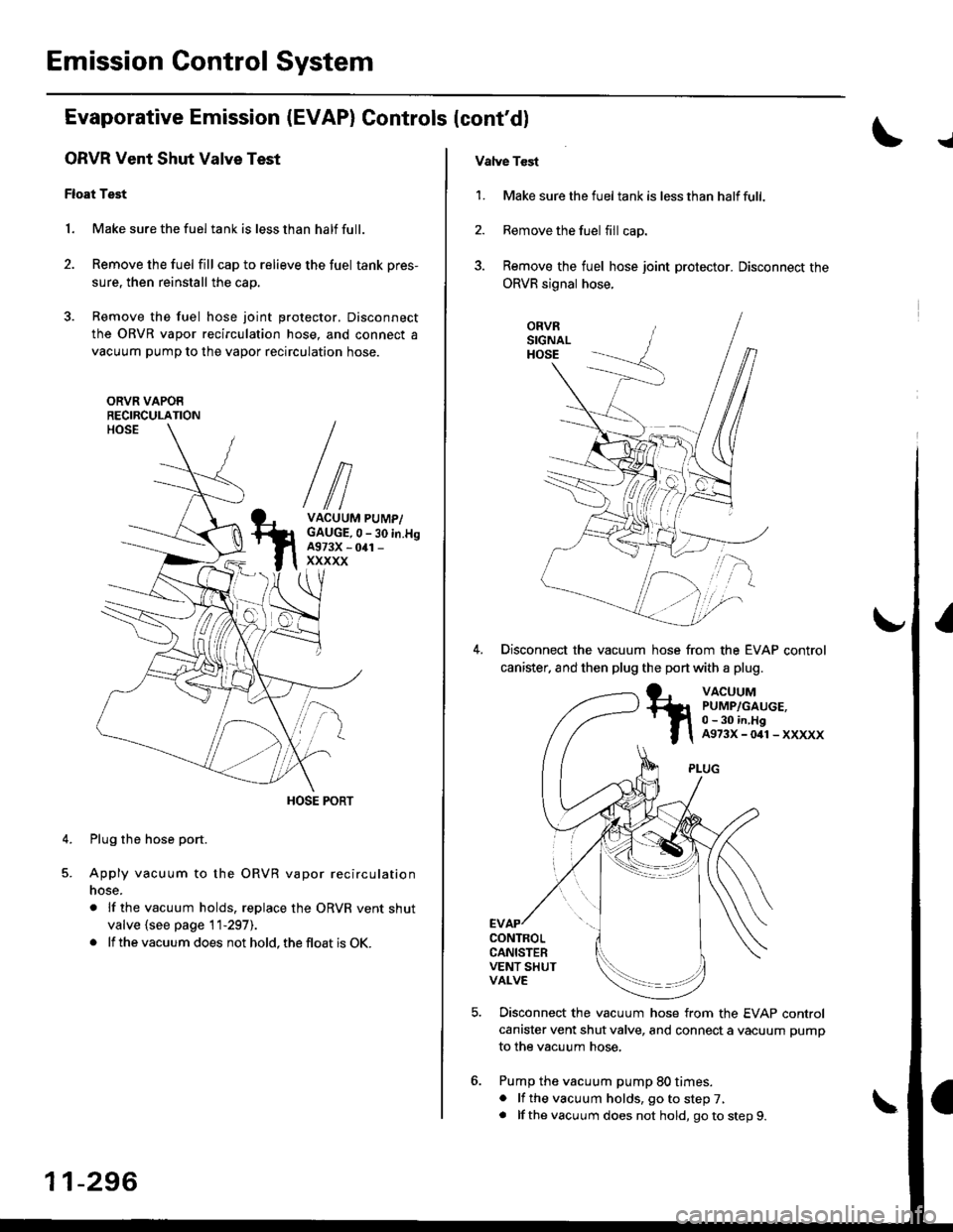
ORVR Vent Shut Valve Test
Float Test
1. Make sure the fuel tank is less than half full.
2. Remove the fuel fill cap to relieve the fuel tank pres-
sure, then reinstall the cap.
3. Remove the fuel hose joint protector. Disconnect
the ORVR vapor recirculation hose, and connect a
vacuum pump to the vapor recirculation hose.
ORVR VAPOERECIRCULATION
VACUUM PUMP/GAUGE,0 - 30 in.H9A973X - 041 -
xxxxx
Plug the hose port.
Apply vacuum to the ORVR vapor recirculation
nose.
. lf the vacuum holds, replace the ORVR vent shut
valve {see page 11-297).
. lf the vacuum does not hold, the float is OK.
4.
11-296
Vatve Tcst
1. Make sure the fueltank is lessthan halffull.
2. Remove the fuel fill cap.
3. Remove the fuel hose joint protector. Disconnect the
ORVR signal hose.
ORVRSIGNALHOSE
Disconnect the vacuum hose from the EVAP control
canister. and then plug the port with a plug.
VACUUMPUMP/GAUGE,0 - 30 in,HgA973X-041-XXXXX
CONTROLCANISTERVENT SHUTVALVE
Disconnect the vacuum hose from the EVAP control
canister vent shut valve, and connect a vacuum pump
to the vacuum hose,
Pump the vacuum pump 80 times.. lf the vacuum holds, go to step 7,. lf thevacuum does not hold, goto step9.
Page 566 of 2189
\
\
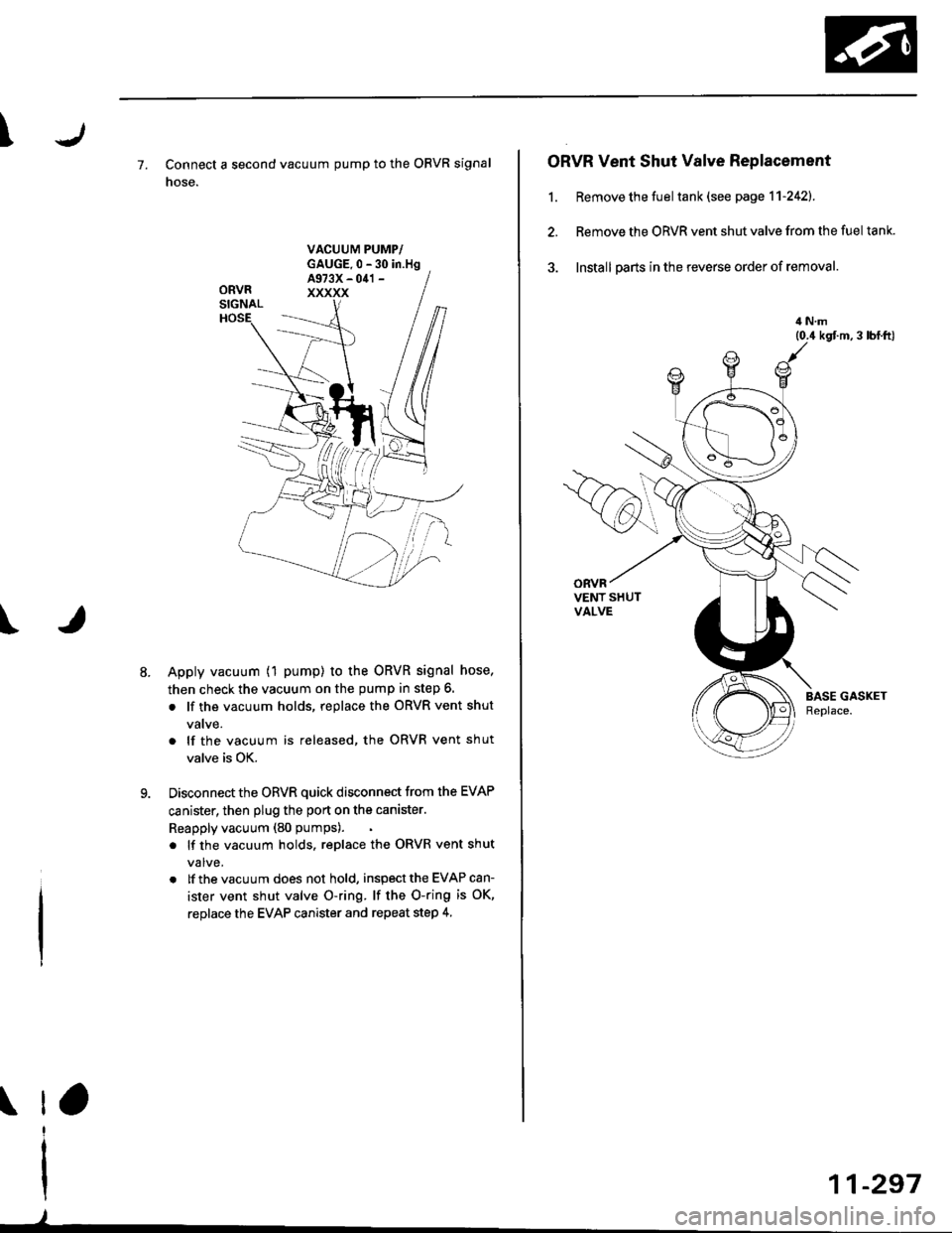
7. Connect a second vacuum pump to the OBVR signal
nose.
VACUUM PUMP/GAUGE.0 - 30 in.HgA973X - 041 -
xxxxx
Apply vacuum (1 pump) to the ORVR signal hose,
then check the vacuum on the pump in step 6.
. lf the vacuum holds, replace the ORVR vent shut
valve.
. lf the vacuum is released, the ORVR vent shut
valve is OK.
Disconnect the ORVR quick disconnect from the EVAP
canister, then plug the port on the canister.
Reapply vacuum (80 pumps).
. lf the vacuum holds, reDlace the ORVR vent shut
valve,
. lf the vacuum does not hold, inspect the EVAP can-
ister vent shut valve O-ring. lf the O-ring is OK,
replace the EVAP canister and repeat step 4.
\
I
11-297
ORVR Vent Shut Valve Replacement
1. Remove the fuel tank (see page 1 1-242).
2. Remove the ORVR vent shut valve from the fuel tank.
3. lnstall oarts in the reverse order of removal.
Page 726 of 2189
Troubleshootin g Procedures
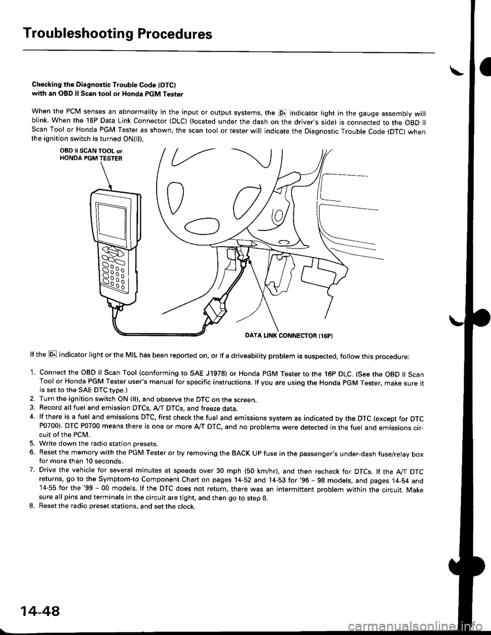
Chccking the Diagnostic Trouble Code IDTC)with an OBD ll Scan tool or Honda PGM Tester
when the PCM senses an abnormality in the input or output systems, the pl indicator light in the gauge assembly willblink. When the 16P Data Link Connector (DLC) (located under the dash on the driver,s side) is connected to the OBD llScan Tool or Honda PGM Tester as shown, the scan tool or tester will indicate the Diagnostic Trouble Code (DTC) whenthe ignition switch is turned ON{ll).
lf the El indicator light or the MIL has been reported on, or lf a driveability problem is suspected, follow this procedure:
1. Connect the OBD ll Scan Tool (conforming to SAE J19781 or Honda PGM Tester to rhe 16p DLC. (See the OBD ll ScanTool or Honda PGM Tester user's manual for specific instructions. lf you are using the Honda PGM Tester, make sure itis set to the SAE DTC type.)
2. Turn the ignition switch ON (lll, and observe the DTC on the screen,3, Record all fuel and emission DTCS, A/T DTCS, and freeze data.4 lf there is a fuel and emissions DTC, first checkthe fuel and emissions system as indicated bythe DTC (except for DTCP0700). DTC P0700 means there is one or more A,/T DTC, and no problems were detected in the fuel and emissions cir-cuit of the PCM.
5. Write down the radio station oresets.
6. Reset the memory with the PGM Tester or by removing the BACK UP fuse in the passenger's under-dash fuse/relay boxfor more than 10 seconds.
7. Drive the vehicle for several minutes at speeds over 30 mph (50 km/hr), and then recheck for DTCS. lf the A"/T DTCreturns, go to the Symptom-to Component Chart on pages 14-52 and 14-53 for'96 - 98 models, and pages 14-54 and14-55 for the'99 - 00 models, lf the DTC does not return, there was an intermittent problem within the circuit. Makesure all pins and terminals in the circuit are tight, and then go to step g.
8. Reset the radio preset stations, and set the clock.
OBD ll SCAN TOOL orHONDA PGM TESTER
DAYA LINK CONNECTOR {16P}
14-44
Page 1323 of 2189
Exterior
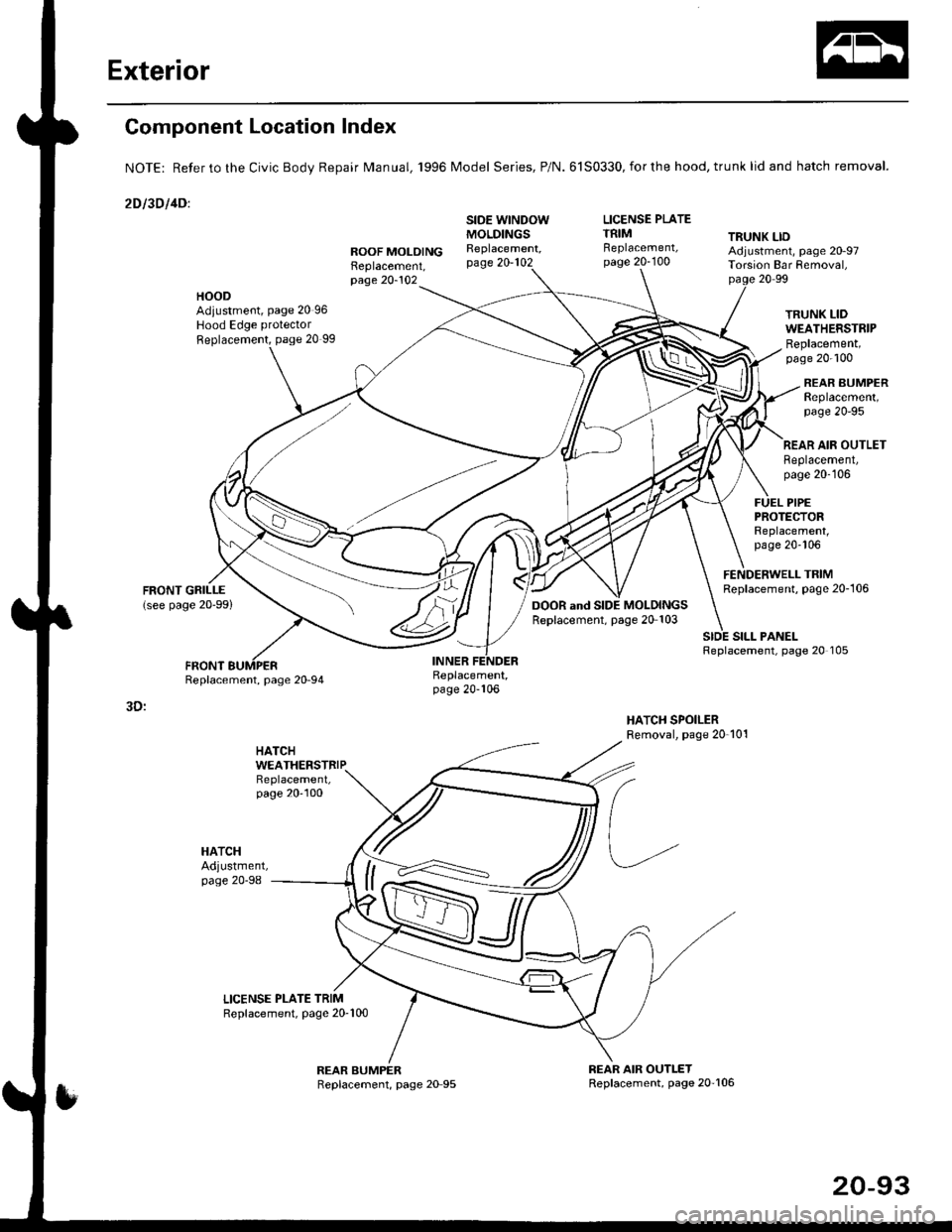
Component Location Index
NOTE: Refer to the Civic BodV Repair Manual, '1996 Model Series, P/N.6150330,forthe hood, trunk lid and hatch removal.
2Dl30llDl
LICENSE PLATETRIM TRUNK LIDROOF MOLOINGReplacement,
SIDE WINDOWMOLDINGSReplacement,page 20-102Replacement,page 20-100Adjustment, page 20-97Tolsion Bar Removal,page 20-10220 99
HOODAdiustment, page 20 96Hood Edge protector
Replacement, page 20 99
TRUNK LIDWEATHERSTRIPReplacement,page 20-100
REAR BUMPERReplacement,page 2O-95
SILL PANELReplacement, page 20 105
REAR AIR OUTLETReplacement,page 20-106
FUEL PIPEPROTEfiORReplacement,page 20-106
FENDERWELL TRIMReplacement, page 20-106
Replacement,page 20-106
3D:
HATCH
HATCHAdjustment,page 20-98
WEATHERSTRIP
20-93
Page 1336 of 2189
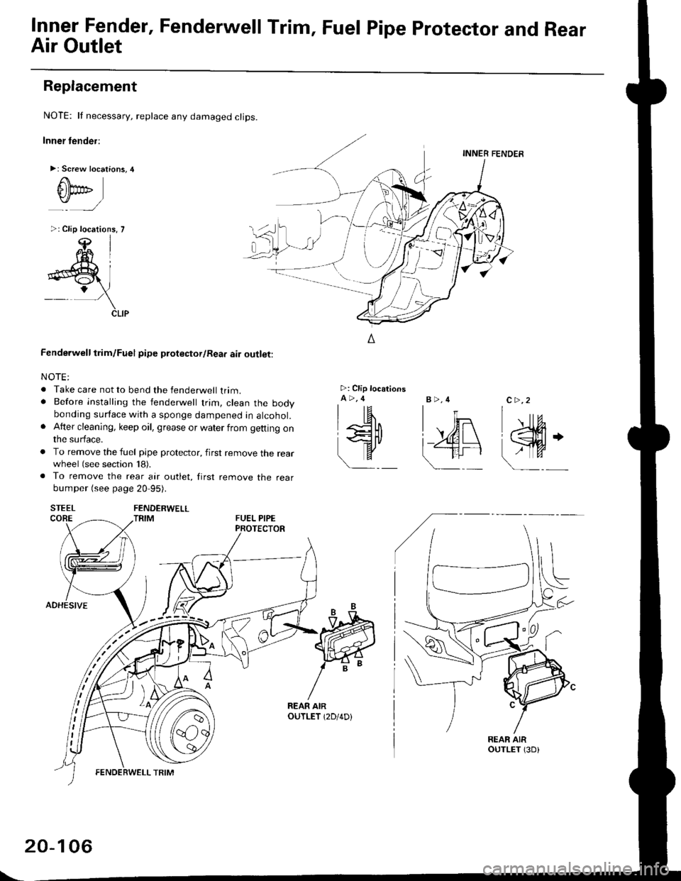
Inner Fender, Fenderwell rrim, Fuel Pipe protector and Rear
Air Outlet
Replacement
NOTE: lf necessary, replace any damaged clips.
Inner tender:
>: Screw locations,4
r\
tllpo" l:,/
>: Clip locations, 7
Fenderwell trim/Fuel pipe protector/Rea. air outlet:
NOTE:
. Take care not to bend the fenderwell trim.. Before lnstalling the fenderwell trim, clean the bodybonding surface with a sponge dampened in alcohol.. After cleaning, keep oil, grease or water from getting onthe surface.
. To remove the fuel pipe protector, first remove the rearwheel (see section 18).. To remove the rear air outlet, first remove the rearbumper (see page 20 95).
STEEL FENDERWELL
>: Clip locationsA>,4B>,4
l;1A
!--l1!
c >,2
I
tAh'frv
\:
+
\-
20-106
Page 1337 of 2189
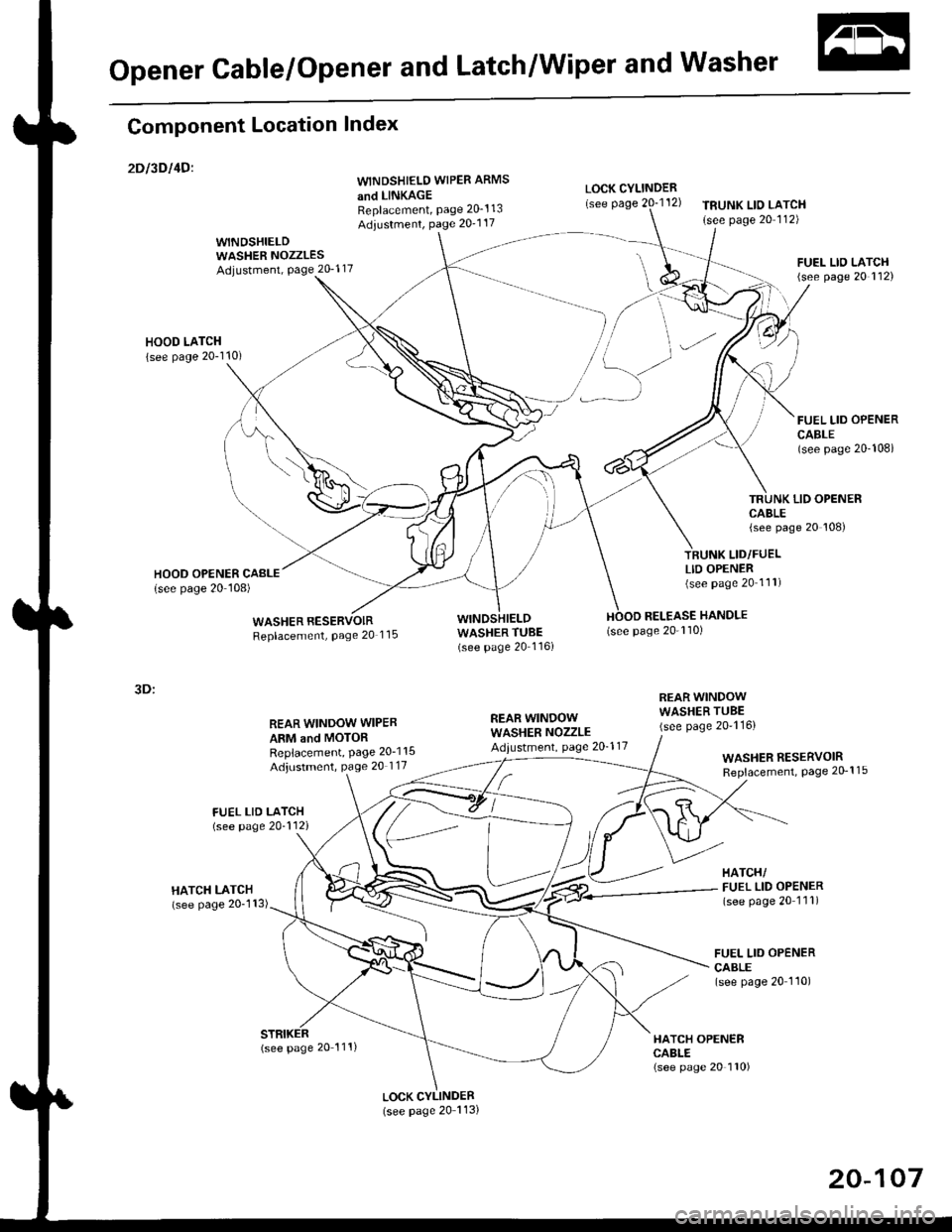
Opener Cable/Opener and Latch/Wiper and Washer
Component Location Index
2Dt3DItD'
y"Tl,"nll,ib?*'r.* o*t"
Replacement, Page 20_1 13
Adiustment, Page 20'1 17
WINDSHIELDWASHER NOZZLESAdjustment, Page 20_1 17
HOOD LATCH
{see page 20-110)
REAR WINDOW WIPER
ARM and MOTORReplacement, Page 20-1 15
Adjustment, page 20 117
LOCK CYLINDER(see page 20 113)
LOCK CYLINDER
TRUNK LIO LATCH
{see page 20 112)
FUEL LID OPENERCABLE(see page 20-108i
LID OPENERCABLE(see page 20 108)
LID/FUELLID OPENER(see page 20 111)
RELEASE HANDLE(see page 20-110)
3D:
REAR WINDOWWASHER NOZZLEAdiustment, page 20-1 17
REAR WINDOWWASHER TUBE(see page 20-116)
HATCH OPENERCABLE(see page 20 110)
WASHER RESERVOIRReplacement, Page 20-1 15
HATCH/FUEL LID OPENER(see page 20 1'11)
FUEL LID OPENERCABLE(see page 20 110)
(see page 20 111)
20-107
Page 1338 of 2189
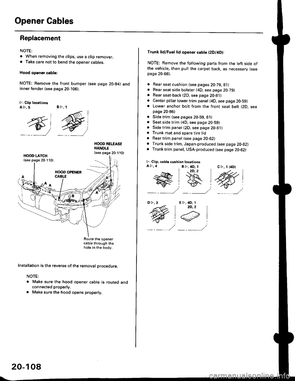
Opener Cables
Replacement
NOTE:
t When removing the clips. use a clip remover.. Take care not to bend the opener cables.
Hood op€ne. cable:
NOTE; Remove the front bumper (see page 20-94) andinner fender (see page 20-106).
>: Clip loc.tionsA >,5 B>, 1
ry)
g
HOOD REI.TASEHANDI.I(see page 20-110)
cable through thehote in th6 body.
Installation is the reverse of the removal procedure.
NOTE:
a Make sure the hood opener cable is routed andconnected properly.
. Make sure the hood opens properly.
20-10a
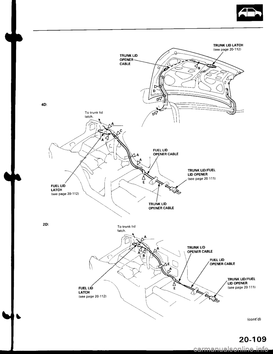
Tlunk lid/Fuel lid opener cabte (2Dl4D):
NOTE: Remove the following parts from rhe Ieft side ofthe vehicle, then pull the carpet back, as necessary {seepage 20-66).
. Rear seat cushion (see pages 20-79, 81). Rear seat side bolster (4D, see page 20,79). Rear seat-back (2D, see page 20-81). Center pillar lower trim panel (4D, seepage20-59)o Lower anchor bolt from the front seat belt {2D. seepage 20-86)
. Side trim (see pages 20-59, 61). Seat side trim (4D, see page 20-59). Side trim panel (2D, see page 20-61). Trunk mat and spare tire lid. Reartrim panel (see page 20-62). Trunk side trim, Japan-produced (see page 20-62). Trunk trim panel, USA-produced (see page 20-62)
>r Clip, cable cushion locationsA >,4 B >,4D_ 1c >, 1 l4D)2D,2
t@#lB
_ : _/ _-___)
E >,4D, 12D,2
@i
_ _,, -/
D>,3
Page 1339 of 2189
TRUNK LID LATCH(see page 20'112)
?e-=....-
4D:
To trunk lidlatch.
latch.
TRUNK LID/FUELLID OPENER(see page 20 111)
TRUNK LID
OPENER CABLE
aA '--!
\- - -l
N"La
FUEL LIDOPEN€R CAELE
TRUNK LID/FUELLID OPENER(see page 20-111)FUELLATCH
(cont'd)
20-109
(see page 20'112)
Page 1340 of 2189
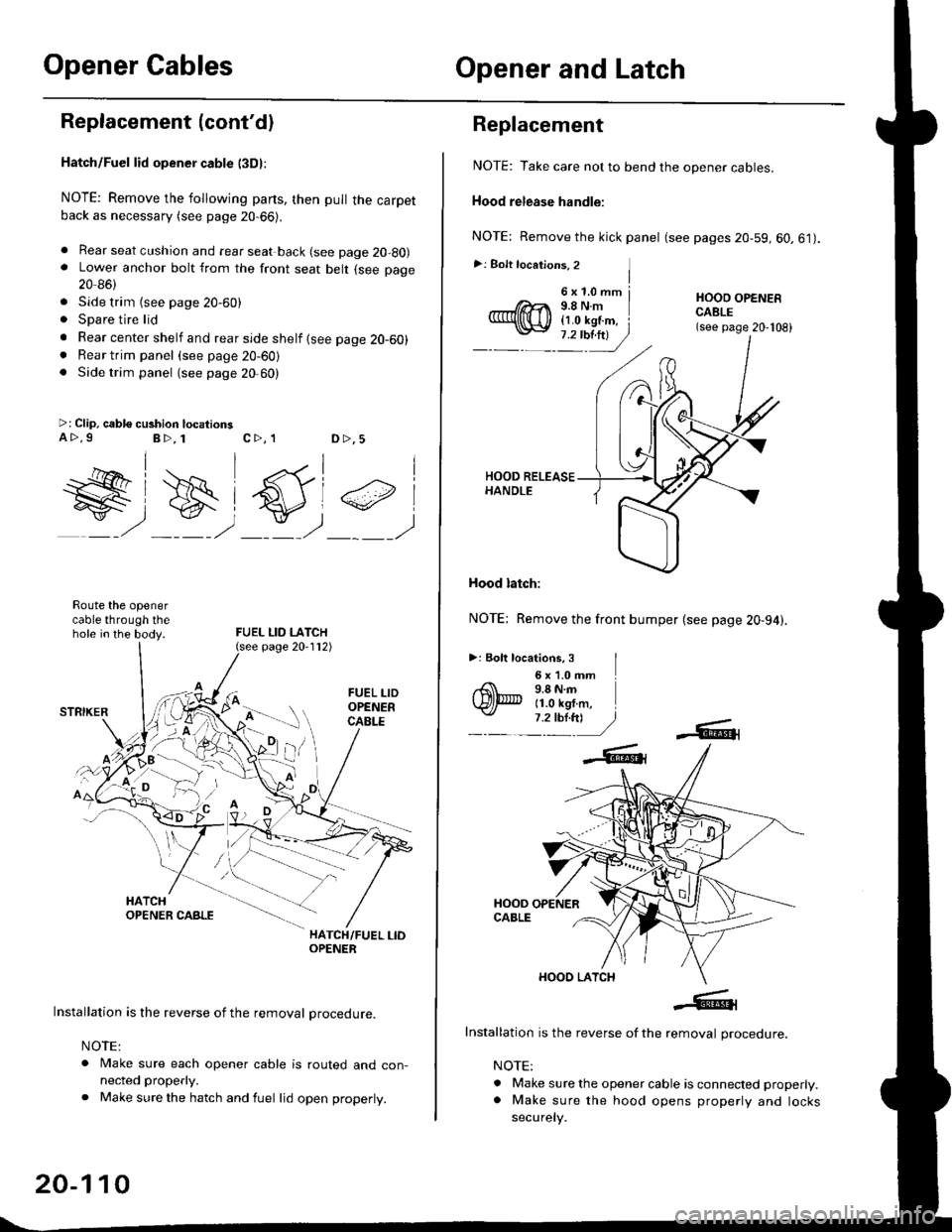
Opener CablesOpener and Latch
Replacement (cont'dl
Hatch/Fuel lid opener cable l3Dl:
NOTE: Remove the following parts, then pull the carpetback as necessary (see page 20-66).
. Rear seat cushion and rear seat back (see page 20-80). Lower anchor bolt from the front seat belt (see page
20 86)
. Side trim {see page 20-60). Spare tire lid
. Rear center shelf and rear side shelf {see page 20-60). Rear trim panel (see page 20-60). Side trim panel (see page 20,60)
>: Clip, cable cushion locationsa>.9B>, 1c>, 1D >,5
W#)
FUEL LID LATCH
#,
Route the openercable through thehole in the body.
HATCH/FUEL LIOOPENER
Installation is the reverse of the removal procedure.
NOTE:
. Make sure each opener cable is routed and con-nected properly.
. Make sure the hatch and fuel lid open properly.
page 20-112)
20-110
6x1.0mm j9.8Nm{1.0 kgf.m, i
Replacement
NOTE: Take care not to bend the opener cables.
Hood release handle:
NOTE: Remove the kick panel (see pages 20-59, 60.61).
>: Bolt locations, 2 ]I
HOOO OPENERCABLE(see page 20-108)
Hood latch:
NOTE: Remove the front bumper (see page 20-94).
>: Eolt locations, 3 I6 x '1.0 mm9.8 N.m11.0 kgf.m,
Installation is the reverse of the removal procedure.
NOTE:
. Make sure the opener cable is connected properly.. Make sure the hood opens properly and locks
securely.
Page 1341 of 2189
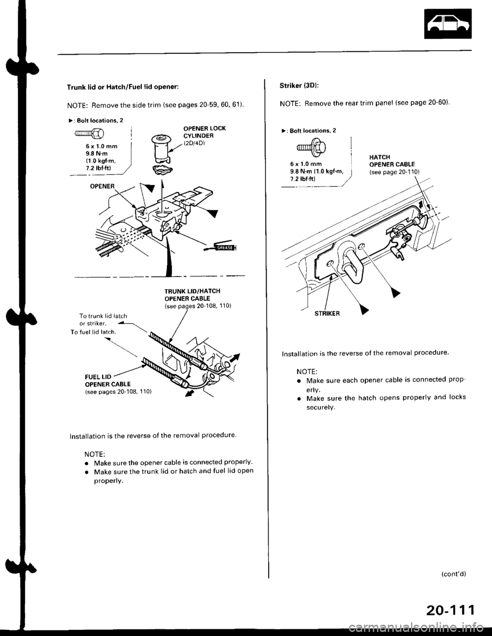
Trunk lid or Hatch/Fuel lid opener:
NOTE: Remove the side trim (see pages 20 59,60.61)
>: Boll locations, 2
OPENER LOCK
6xl.0mm9.8Nm11.0 kgf.m,7.2 tbl.ttl
a@- CYLINDER
Ya//t2't4Dl
ti
TBUNK LID/HATCHOPENER CABLE(see20-108, 110)
To trunk lid latchor striker.
To fuel lid latch. \
FUEL LIDOPENER CABLE(see pages 20-108, '110)
Installation is the reverse of the removal procedure
NOTE:
. lvake sure the opener cable is connected properly.
. Make sure the trunk lid or hatch and fuel lid open
properly.
l:'.j
Striker (3Dl:
NOTE: Remove the rear trim panel (see page 20-60)
>: Bolt locations, 2
6xl.0mmHATCHOPENER CAELE(see page 20-110)
lnstallation is the reverse of the removal procedure.
NOTE:
. N4ake sure each
erlY.
. Make sure the
securelY.
opener cable is connected ProP-
hatch opens properly and locks
(cont'd)
20-111