HONDA CIVIC 1999 6.G Workshop Manual
CIVIC 1999 6.G
HONDA
HONDA
https://www.carmanualsonline.info/img/13/6068/w960_6068-0.png
HONDA CIVIC 1999 6.G Workshop Manual
Trending: check oil, Clutch, Door control unit, fuel filter location, piston ring, refrigerant type, Ac compressor
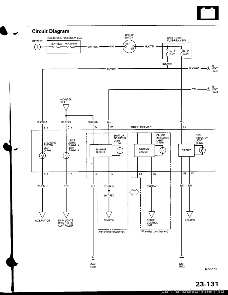
Page 1601 of 2189
IJNOER,DASHFUSE/RELAY BOX
GAUGELIGHTS
l3wx4 l
CHARGINGSYSTEMLIGHT0.4w)
Gircuit Diagram
UNDEN HOOD FUSE/RELAY BOXIJ
N0.30 (7.54)FUSE
f7
I
tlRED/BLK BEO/BLK
l"l"8LK BLU
IJ
l'"^*
I
t-
G401G402
__l
tE2
IFED/BLU
CRUISECONTROTUNIT
fl ,,1:
tH
I c12
IFFD
VDASH LIGHTSBRIGHTNESSCONTROLLEF
l"'WHT/BLU
vALTERNATOR
(With shifi-up indicatd lighl)(wi1h cruise conlrcl system)
Page 1602 of 2189
Gauge Assembly
(Wnh lachomolgr)
I cNfldt--]I CONTRoL II MODULE
I 0cM) :
tvl
i.ll
|
-i;,
i
TURN SIGNAUHAZAROWARNINGswtTcH
Circuit Diagram {cont'd)
Fh"lurous @)- BLrcwHT + BLKryEL
fi'Sfvrous 16r.- veLPAGE
RIGHT
V
IGR&ryE
LEFT
V
I
No.s (104)FUSE
V
IBEO/GRN
lru
8LU4RE0
ABSCONTROLUNIT
-rl
eLui'rvrr
G401G402G401G442
23-132
Page 1603 of 2189
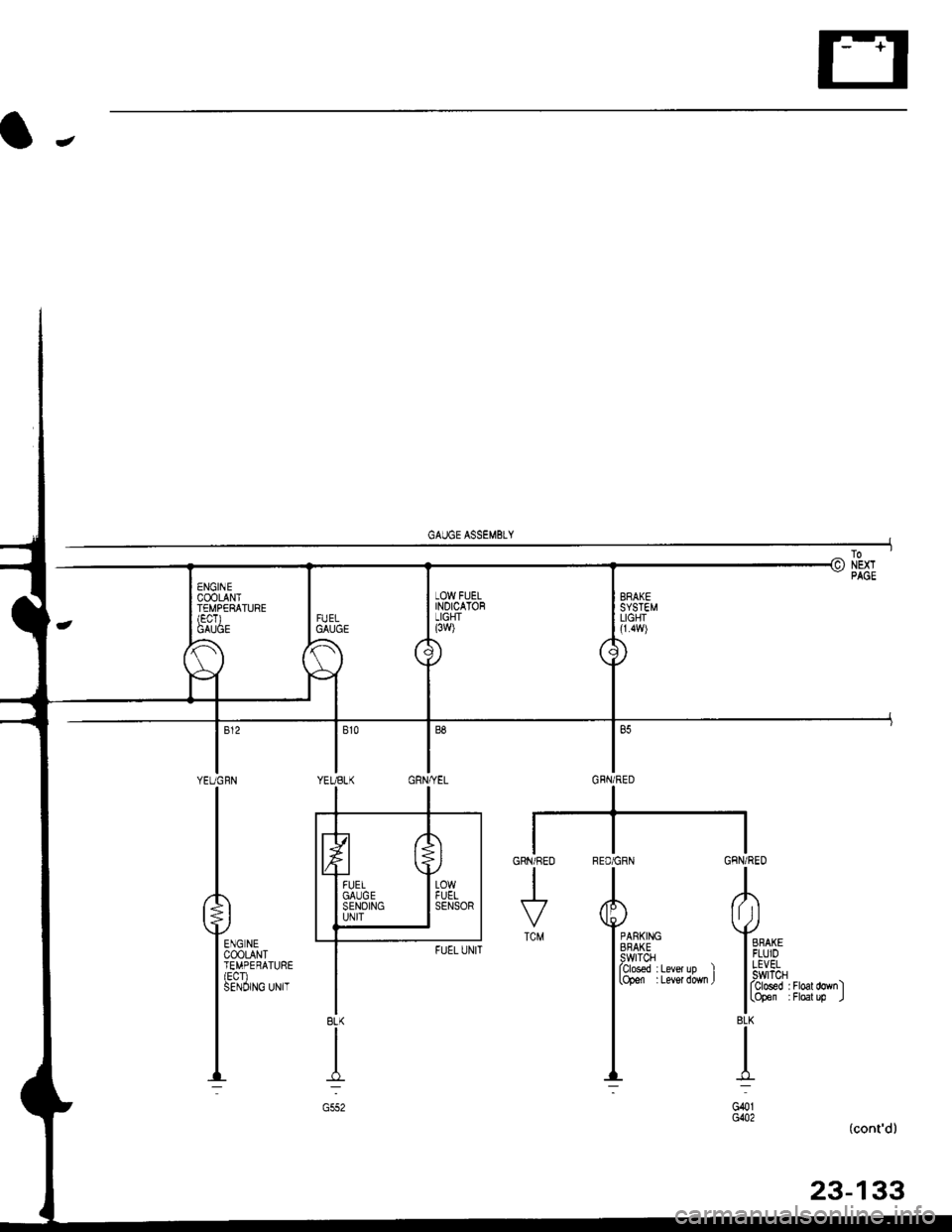
BRAKESYSTEMLIGHI(1.4w)
RED/GRN GFN/RED
TA
Yimi+" Yo
l[3&1" ;i:l"la',.l l,,1!:,iT "*,,
I lrb'ff" ;i#il;-"1
I'i
_,L J-:-l
G401G()2
GRN/REO
I
TCM
(cont'd)
23-133
8LK
I
G552
Page 1604 of 2189
Gauge Assembly
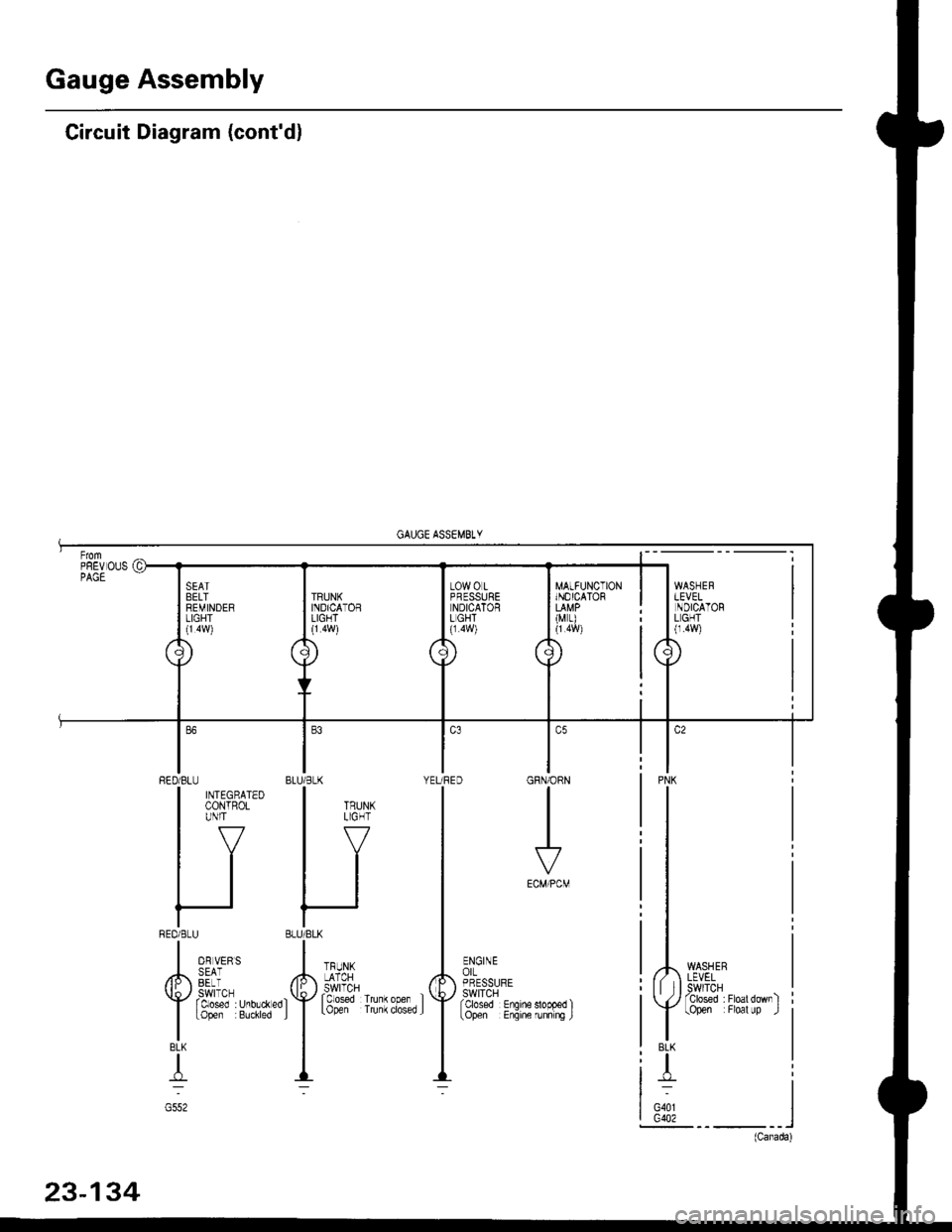
Circuit Diagram (cont'dl
MATFUNCTIONINOICATOR
(M r)
WASHERLEVELSWITCHTclosed :Floatdownltopen Floal up .l
PNK
BLK
T
G401G402
GRN/ORN
I
ECM/PCM
ENGINEorLPRESSURESWITCHfcbsed Enqine
BLU/BLK YEURED
HI
'f''#lu""',.'f
--
RED/BLU
| ffitt'*'
IV
tl
tl
REDi BLU
I o, u,,,
/h,, SEii
Y rtt'J"T,r.0,.*"0
I
topen Buchred
BLK
T
G552
Page 1605 of 2189
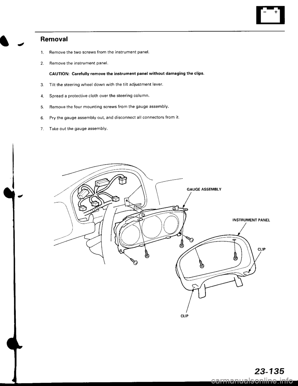
JRemoval
1. Remove the two screws from the instrument panel.
2. Remove the instrument panel.
CAUTION: Carefully remove the instrument panel without damaging the clips.
3. Tilt the steering wheel down with the tilt adjustment lever.
4. Spread a protective cloth over the steering column.
5. Remove the four mounting screws from the gauge assembly.
6. Pry the gauge assembly out, and disconnect all connectors from it
7- Take out the gauge assembly.
GAUGE ASSEMBLY
INSTRUMENT PANEL
23-135
Page 1606 of 2189
Gauge Assembly
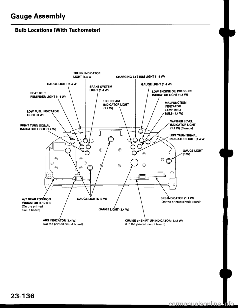
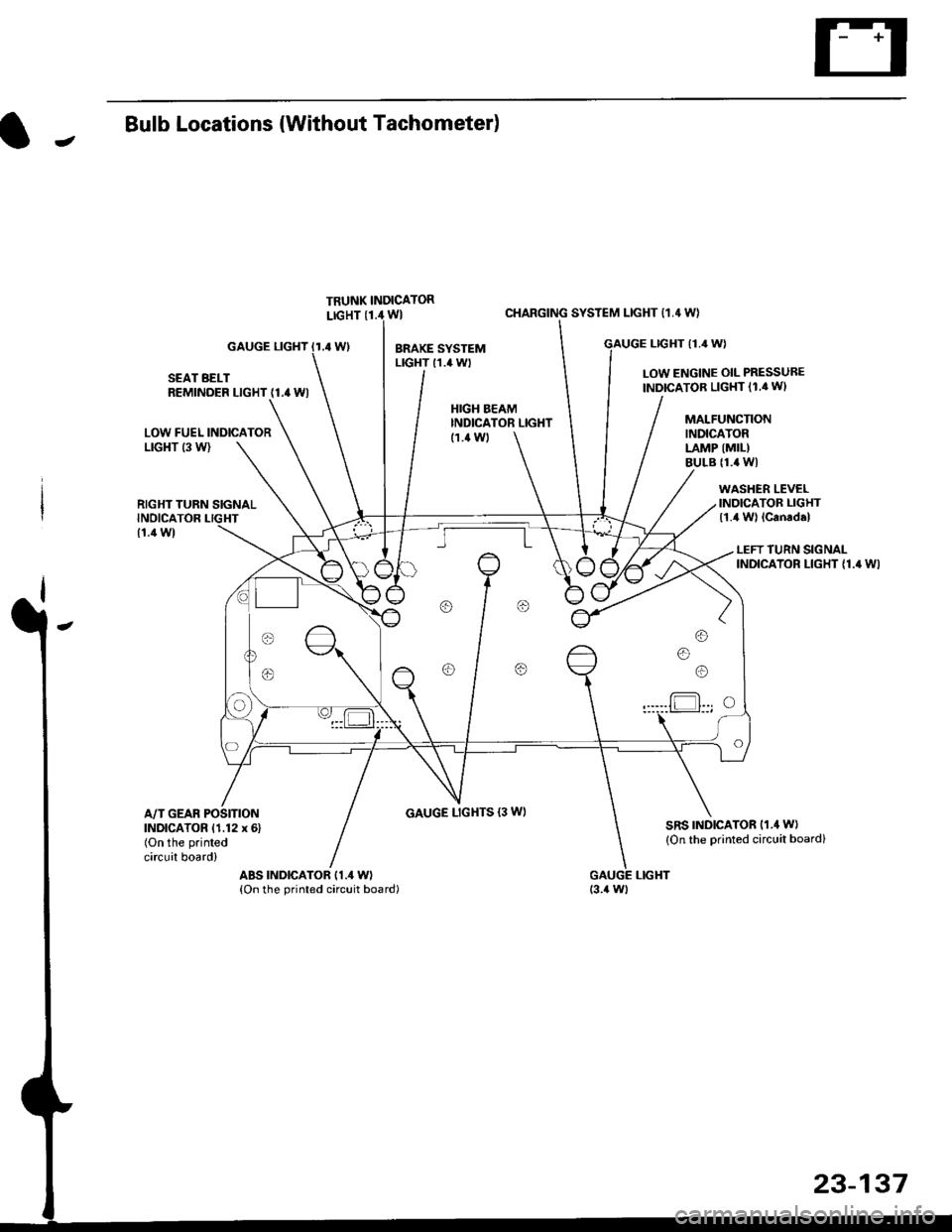
Bulb Locations (With Tachometer)
GAUGE LIGHT II.' WI
SEAT BELTREMINDER LIGHT I1.4 WI
LOW FUELLIGHT 13 W)
RIGHT TURN SIGNALINDICATOR LIGHT I1.4 WI
A/T GEARGAUGE LIGHTS 13 W)
CI{ARGING SYSTEM LIGHT (1.,1W)
GAUGE I-IGHT {1,4 WI
LOW ENGINE OIL PRESSUREINDICATOR LIGHT (1,' W}
HIGH EEAMINDICATOR LIGHT(1.4 W)
GAUGE LIGHT l3.il Wl
MALFUNCTIONINDICATORLAMP {MIL}BULE (1.{ Wl
WASHER I.'C VELINDICATOR LIGHT{1.4 Wl (Canada)
LEFT TURN SIGNALINDICATOR LIGHT {1.4 WI
sRsTOB (1.4 Wl
{On the printed circuit board)INDICATOR (1.12 x 6l(On the printed
circuit board)
ABS |ND|CATOR (1.. Wl{On the printed circuit board)CRUISE or SHIFT-UP INDICATOR 11.12 11.{On the orinted circuit board)
23-136
Page 1607 of 2189
JBulb Locations {Without Tachometer)
TRUNK INDICATORLIGHT {1.i1W}
.4 Wl
CHARGING SYSTEM LIGHT 11,4 W}
LTGHT (1.4 W)GAUGE LIGHT
SEAT BELTREMINDER LIGHT (1.4 WI
LOW ENGINE OIL PRESSUBE
INDICATOB LIGHT (1.4 WI
LOW FUEL INDICATORLrGl{T (3 W)
RIGHT TURN SIGNALINOICATOR LIGHT
(1.1Wt
GAUGE LIGHTS {3 WI
WASHER LEVELINDICATOR LIGHT{1.4 W} lcanad.l
HIGH BEAMINDICATOR LIGHTMALFUNCTIONINDICATORLAMP (MIL)
BULB {1.4 WI
{1.ilW)
LEFT TURN SIGNALINDICATOR LIGHT {1.4 WI
A/T GEAR POSITIONINDICATOR (1.12 x 6)(On the printed
circuit board)
sRs TND|CATOR 11.4 W)
{On the Drinted circuit board}
aBs tNDtcAToR t1.4 W)(On the printed circuit board)(3.{ Wt
o/ o \7 o
23-137
Page 1608 of 2189
Gauge Assembly
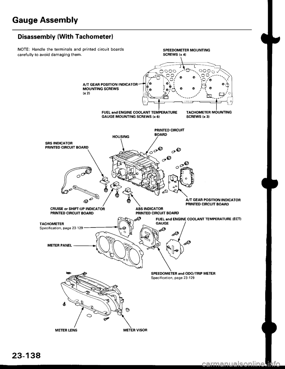
Disassembly (With Tachometerl
NOTE: Handle the terminals and Drinted circuit boards
carefully to avoid damaging them.
A/T GEAR POSITION INDICAMOUNNNG SCREWStx 2)
FUEL and ENGINE COOLANT TEMPEMTUREGAUGE MOUNTING SCREWS {x 6,TACHOMETEB MOUNTINGSCREWS lx 3l
ao
,-ook+r
.,- ll $
t'{"{q.' ElI ..il \:r
A/T GEAR POSITION INOICAPRINTED CIRCUIT BOARD
INDICATORPRINTED CIRCUIT BOARD
@ FUEL end ENGINE COOLANT TEMPERATURE (ECTI
PRINTEO CIRCUIT
q,
6\
ABSCRUISE or SHIFT-UP INDICATORPRINTED CIRCUTT EOARD
TACHOMETERSpecilication, page 23 129
METER PANEL
booo .--:o'-..oooo.A
:-F.-sr'; "€?;"')
aFl l!
GAUGE
23-134
Page 1609 of 2189
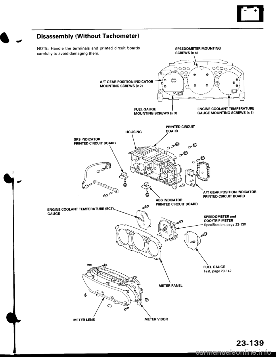
JDisassembly {Without Tachometerl
NOTE: Handle the terminals and printed circuit boards
carefully to avoid damaging them.
SPEEDOMETER MOUNTINGSCREWS (x 4)
A/T GEAR POSITION INDICAMOUNTING SCREWS {x 2l
SRS INOICATORPRINTED CIRCUIT BOARD
ENGINE COOLANT TEMPERATURE {ECT}
GAUGE
ABS INDICATORPRINTED CIRCUIT BOARD
PRINTED CIRCUIT
METER PANEL
FUEL GAUGEMOUNTING SCREWS {x 3)ENGINE COOLANT TEMPERATUR€GAUGE MOUNTING SCREWS {x 3l
A/T GEAR POSITION INDICATOR
PRINTED CIRCUIT BOARD
'a@
.-@--o
o"i^>
Er t
lmwp\
d*re
\*P
\
FUELTest,GAUGEpage 23-142
oOo ,.-'€'-., oOOo -/\
€3,'" ' "$?'----"')
)a.' '.,,'+ ':j
\ll Lto
BOARD
METER LENSMETER VISOR
23-139
Page 1610 of 2189
Vehicle Speed Sensor (VSSI
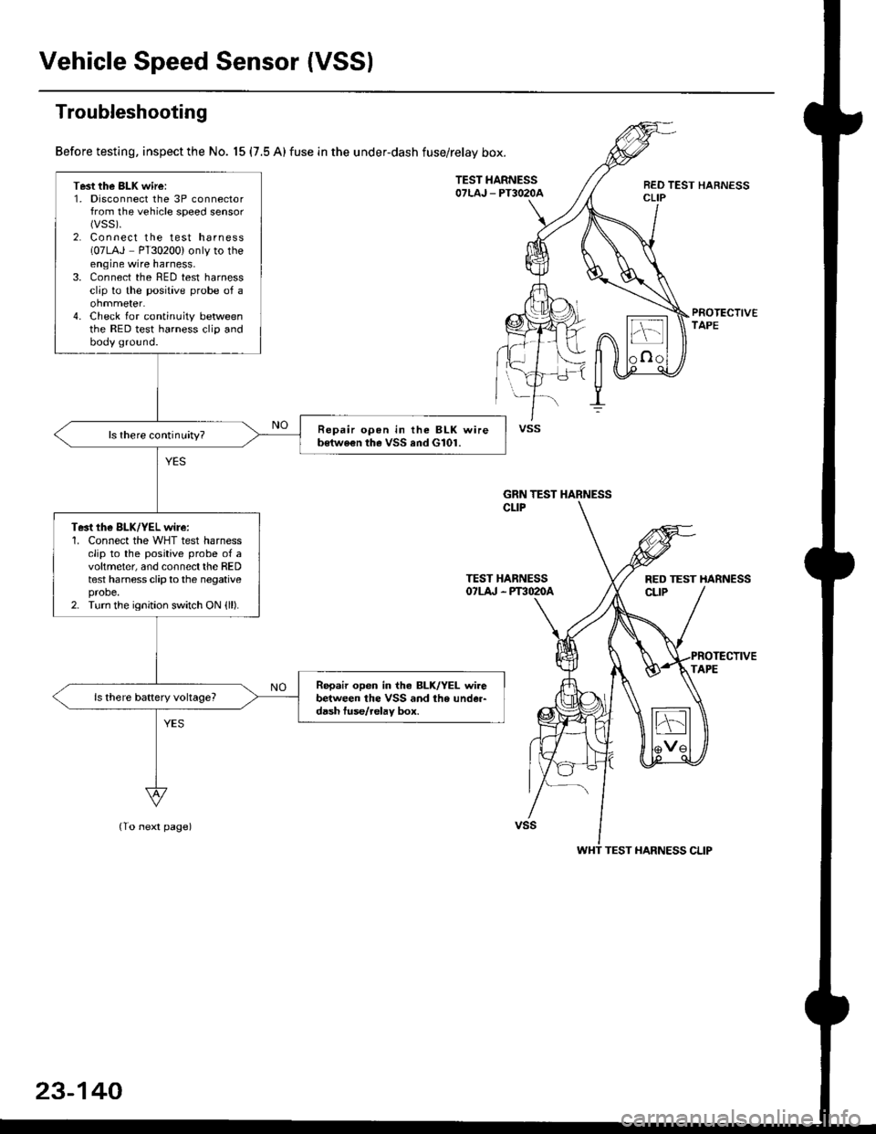
Troubleshooting
Before testing, inspect the No. 15 (7.5 A) fuse in the under-dash fuse/relay box.
TEST HARNESSOTLAJ _ PT3O2OAREO TEST HARNESSCLIP
PROTECTIVETAPE
TEST HARNESSOTLA' . PT3O2OA
(To next page)
Test the BLK wire:1. Disconnect the 3P connectorfrom the vehicle speed sensor(vss).
2. Connect the test harness(07LAJ PT30200) only to theengine wire harness,3. Connect the RED test harnessclip to the positive probe of a
4. Check for continuity betweenthe RED test harness clip andbody ground.
Repair opon in the BLK wireb€twe€n the VSS and G101.ls there continuity?
Te3t the BLK/YEL wire:1. Connect the WHT test harnessclip to the positive probe of avoltmeter, and connectthe REDtest harness clip to the negativeprobe.2. Turn the ignition switch ON {ll).
Repair open in iho BLK/YEL wirebetween the VSS and the under-d6sh tuse/relav box.
vss
GRN TEST HARNESS
RED TEST HARNESS
WHT TEST HARNESS CLIP
23-140
Trending: spare tire, Gearbox oil, horn, Hood, Rocker arm torque, D16y8, Clutch plate
![HONDA CIVIC 1999 6.G Workshop Manual Gauge Assembly
(Wnh lachomolgr)
I cNfldt--]I CONTRoL II MODULE
I 0cM) :
tvl
i.ll
|
-i;,
i
TURN SIGNAUHAZAROWARNINGswtTcH
Circuit Diagram {contd)
Fh"lurous @)- BLrcwHT + BLKryEL
fiSfvrous 16r.- veL HONDA CIVIC 1999 6.G Workshop Manual Gauge Assembly
(Wnh lachomolgr)
I cNfldt--]I CONTRoL II MODULE
I 0cM) :
tvl
i.ll
|
-i;,
i
TURN SIGNAUHAZAROWARNINGswtTcH
Circuit Diagram {contd)
Fh"lurous @)- BLrcwHT + BLKryEL
fiSfvrous 16r.- veL](/img/13/6068/w960_6068-1601.png)
