6-1 HONDA CIVIC 1999 6.G User Guide
[x] Cancel search | Manufacturer: HONDA, Model Year: 1999, Model line: CIVIC, Model: HONDA CIVIC 1999 6.GPages: 2189, PDF Size: 69.39 MB
Page 129 of 2189
Timing Belt
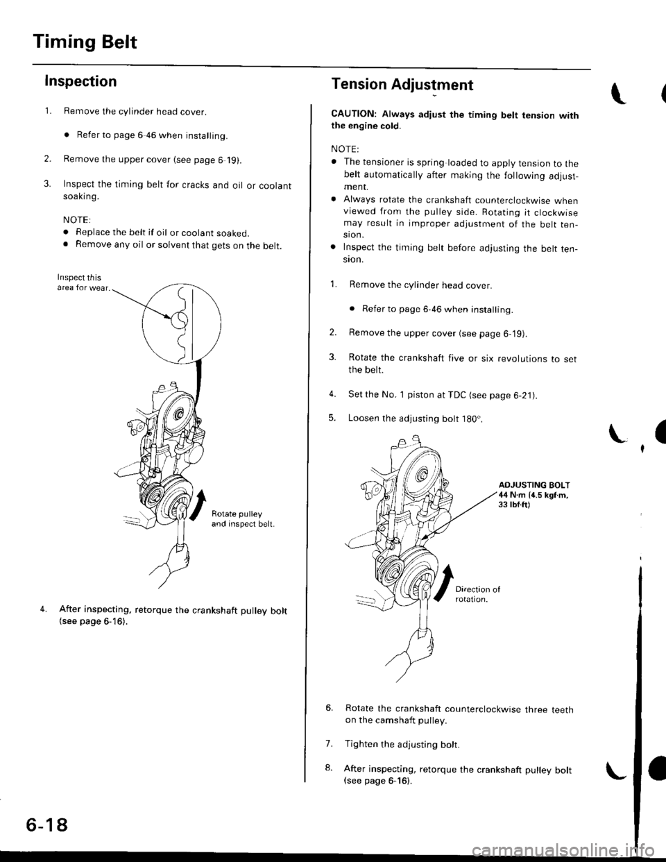
Inspection
1.
2.
3.
Remove the cylinder head cover.
. Refer to page 6 46 when installing.
Remove the upper cover (see page 6 19).
Inspect the timing belt for cracks and oil or coolantsoakrng.
NOTE:
. Replace the belt if oil or coolant soaKeo.. Remove any oil or solvent that gets on the belt.
Rotate pulleyand inspect belt.
After inspecting, retorque the crankshaft pullev bolt{see page 6- 16).
o- I6
Tension Adjustment
CAUTION: lt*ays aa;j"t the timing bett rension withthe engine cold.
NOTE:
. The tensioner is spring loaded to apply tension to thebelt automatically after making the following adjustment.
. Always rotate the crankshaft counterclockwise whenviewed from the pulley side. Rotating it clockwisemay result in improper adjustment of the belt ten-sion.
. lnspect the timing belt before adjusting the belt ten-ston.
1.Remove the cylinder head cover.
. Refer to page 6,46 when installing.
Remove the upper cover (see page 6,'19).
Rotate the crankshaft five or six revolutions to setthe belt.
Set the No. 'l piston at TDC (see page 6-21).
Loosen the adjusting bolt 180'.
2.
3.
4.
5.
\I
ADJUSTING BOLT44 N.m {4.5 kgt m,33 rbf.ft)
7.
8.
Rotate the crankshaft counterclockwise three teethon the camshaft pulley.
Tighten the adjusting bolt.
After inspecting, retorque the crankshaft pulley bolt(see page 6-16).
Page 130 of 2189
Removal
NOTE:
. Replace the timing belt at 105,000 miles (168.000 km)
according to the maintenance schedule (normal con-
ditions/severe conditions).
lf the vehicle is regularly driven in one or more of the
followlng conditions, replace the timing belt at 60.000
miles (U.S.A.) 100,000 km {Canada).
.In very high temperatures (over 110'F.43'C)
. In very low temperatures (under -20'F, -29"C)'
! Turn the crankshaft pulley so the No. 1 piston is at
top dead center (TDC) before removing the belt (see
page 6'21).
. Inspect the water pump before installing the timing
belt {see Page 10-14).
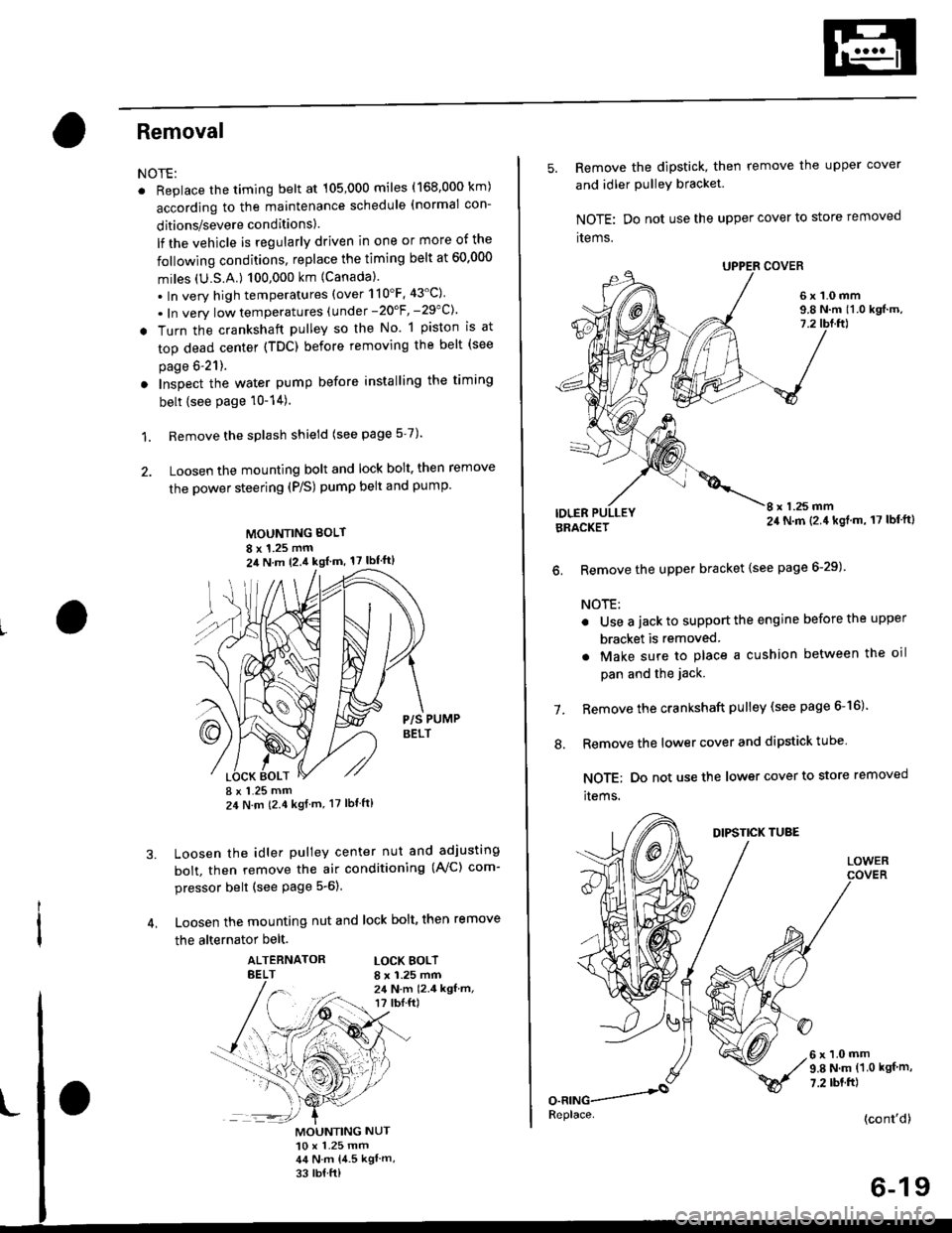
1. Remove the splash shield (see page 5-7).
2. Loosen the mounting bolt and lock bolt. then remove
the power steering (P/S) pump belt and pump
MOUNTING BOLT
8 x 1.25 mm2il N m 12.4 kgl m, 17 lbf'ft)
P/S PUMPBELT
I x 1.25 mm24 N m (2.4 kgf m, 17 lbt ft)
Loosen the idler pulley center nut and adjusting
bolt, then remove the air conditioning (AVC) com-
pressor belt (see Page 5-6).
Loosen the mounting nut and lock bolt, then remove
the alternator belt.
ALTERNATORBELTLOCK BOLTI x 1.25 mm24 N.m 12.4 kgf.m,r? tbI.ft)
3.
MOUNTING NUT10 x 1.25 mm44 N.m 14.5 kgl m,
33 rb{ ft)
5. Remove the dipstick, then remove the upper cover
and idler PulleY bracket
NOTE: Do not use the upper cover to store removed
items.
6x1.0mm9.8 N.m 11.0 kgf.m,7.2
IDLERI x 1.25 mm24 N.m (2.4 kgl.m, 17 lbf'ft)BRACKET
6. Remove the upper bracket {see page 6-29)
NOTE:
. Use a jack to support the engine before the upper
bracket is removed
. Make sure to place a cushion between the oil
pan and the jack.
Remove the crankshaft pulley (see page 6-16).
Remove the lower cover and dipstick tube
NOTE; Do not use the lower cover to store removed
items.
1.
.'.
DIPSTICK TUBE
LOWER
6x1.0mm9.8 N.m (1.0 kgf m,
7.2 rbt.ft)
(cont'd)
6-19
Replace.
Page 132 of 2189
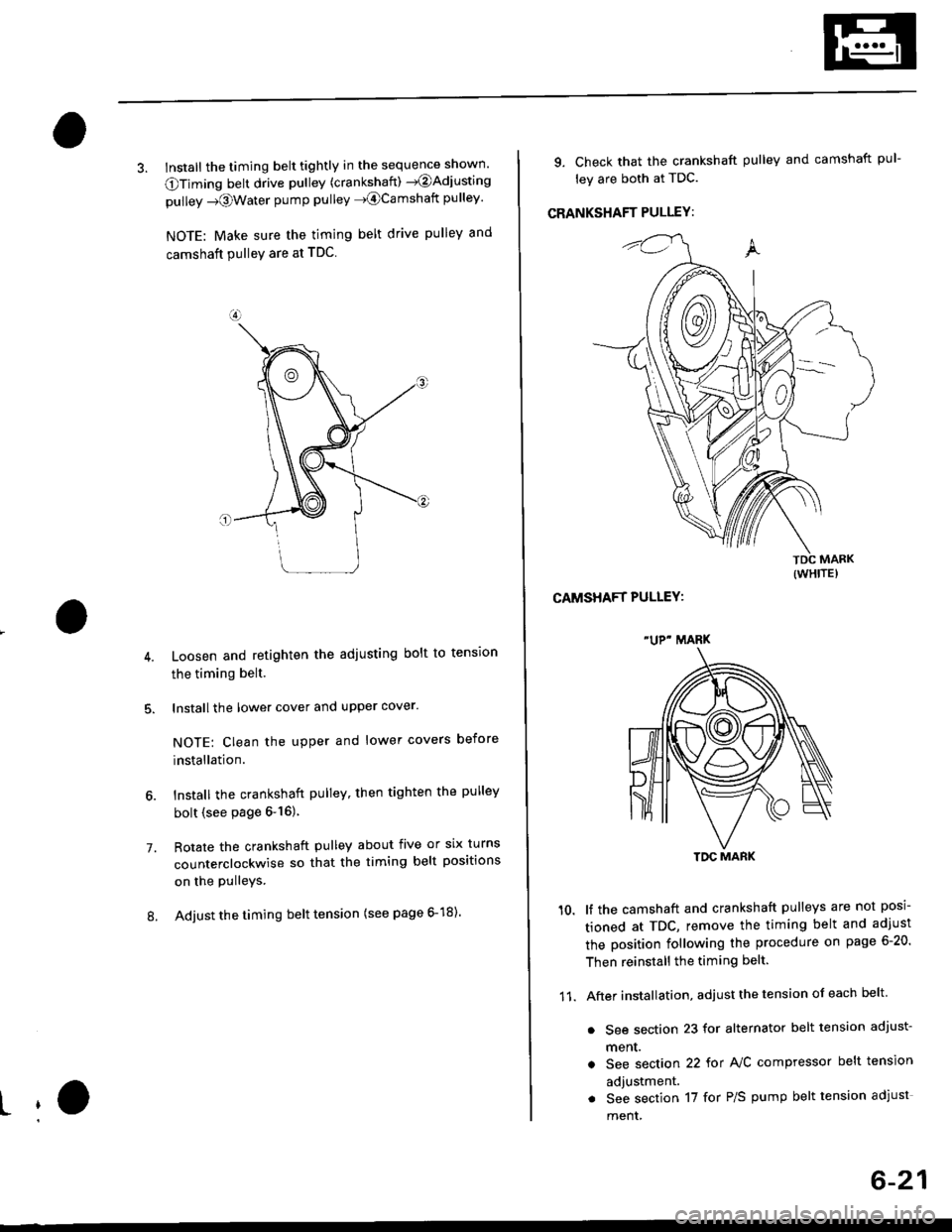
3. Install the timing belt tightly in the sequence shown'
OTiming belt drive pullev (crankshaft) )@Adjusting
pulley -towater pump pulley J@Camshatt pulley'
NOTE: Make sure the timing belt drive pulley and
camshaft PulleY are at TDC
7.
Loosen and retighten the adiusting bolt to tension
the timing belt.
lnstall the lower cover and upper cover.
NOTE: Clean the upper and lower covers before
installation.
lnstall the crankshaft pulley, then tighten the pulley
bolt (see page &16)
Rotate the crankshaft pulley about five or six turns
counterclockwise so that the timing belt positions
on the Pulleys.
Adjust the timing belt tension (see page 6-18).8.
L
9. Check that the crankshaft pulley and camshaft pul-
ley are both at TDC.
CRANKSHAFT PULLEY:
CAMSHAFT PULLEY:
lf the camshaft and crankshaft pulleys are not posi-
tioned at TDC, remove the timing belt and adjust
the position following the procedure on page 6-20'
Then reinstall the timing belt.
After installation, adjust the tension of each belt
. See section 23 for alternator belt tension adjust-
ment.
a See section 22 tot NC compressor belt tension
adjustment.
. See section 17 for P/S pump belt tension adjust
ment,
(wHrTE)
"UP" MARK
TDC MARK
11.
6-21
Page 133 of 2189
Crankshaft Speed Fluctuation (CKF) Sensor
2.
3.
5.
Replacement
4.
1.
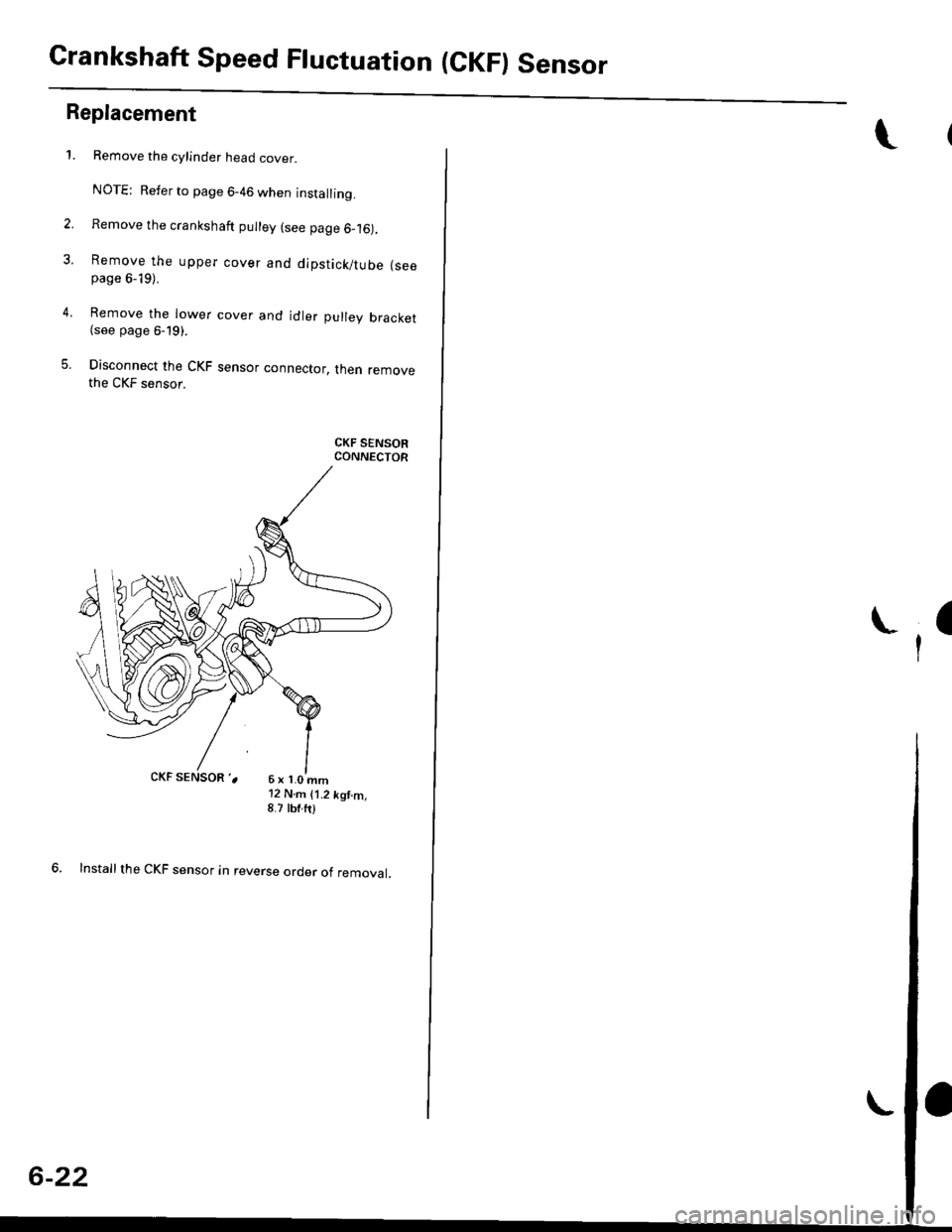
6x1.0mm'12 N.m {1.2 kgt.m,8.7 tbf.ft)
6. Installthe CKF sensor in reverse order of removal.
Remove the cylinder head cover.
NOTE: Refer to page 6-46 when installing.
Remove the crankshaft pulley (see page 6_16),
Remove the upper cover and dipstick/tube {seepage 6-19).
Remove the lower cover and idler pulley bracket(see page 6-19).
Disconnect the CKF sensor connector, then removethe CKF sensor.
CKF SENSORCONNECTOR
6-22
:(
I
Page 138 of 2189
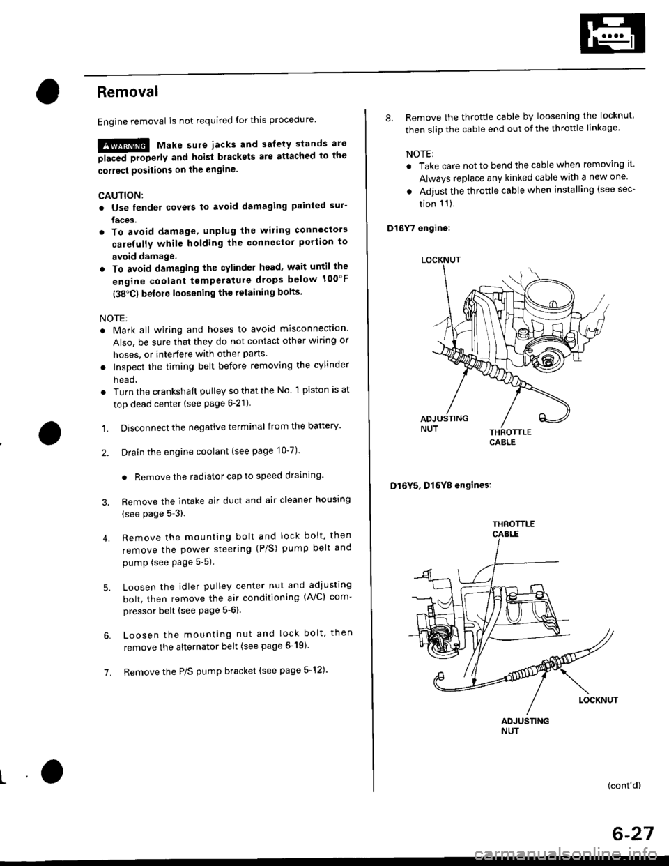
Removal
Engine removal is not required for this procedure
!!!s@ Make sure iacks and salety stands are
f ta"eata"ea propetty and hoist brackets are attached to the
correct positions on the engine.
CAUTION:
. Use tender covels to avoid damaging painted sul-
faces.
o To avoid damage, unplug the wiling connectors
carefully while holding the connector portion to
avoid damage.
. To avoid damaging the cylinder head, wait until the
engine coolant temperature drops below 100"F
{38"C} before loossning the tetaining bolts.
NOTE:
o Mark all wiring and hoses to avoid misconnectlon
Also, be sure that they do not contact other wiring or
hoses, or interfere with other parts.
. Inspect the timing belt before removing the cylinder
h ead.
. Turnthe crankshaft pu lley so that the No. lpistonisat
top dead center (see Page 6-21)
'1. Disconnect the negative terminal from the battery'
Drain the engine coolant (see page'10-7).
a Remove the radiator cap to speed draining.
Remove the intake air duct and air cleaner housing
(see page 5 3).
Remove the mounting bolt and lock bolt. then
remove the power steering (P/S) pump belt and
pump (see page 5'5).
Loosen the idler pulley center nut and adjusting
bolt' then remove the air conditioning (A'lc) com-
pressor belt (see Page 5-6).
Loosen the mounting nut and lock bolt. then
remove the alternator belt (see page 6-19).
Remove the P/S pump bracket (see page 5-12).
3.
4.
2.
6.
1.
8. Remove the throttle cable by loosening the locknut,
then slip the cable end out of the throttle linkage
NOTE:
. Take care not to bend the cable when removing it
Always replace any kinked cable with a new one
. Adjust the throttle cable when installing (see sec-
tion 1 1).
D16Y7 engine:
Dl6Y5, Dl6Y8 engines:
THFOTTLECABLE
(cont'd)
6-27
LOCKNUT
CABLE
Page 141 of 2189
Cylinder HeadRocker Arms
18.
19.
21.
22.
Removal (cont'd)
Remove the timing belt {see page 6-19).
Remove the camshaft pulley and back cover,
CAMSHAFTPULLEYClean when installing.
6x1.0mm8 x 1.25 mm37 N.m (3.8 kgf.m,21 tbtlrlApply engine oilto thebolt threads.
Remove the exhaust manifold {see pages 9-6 and 9_7).
Remove the intake manifold (see pages 9-2 thru 4).
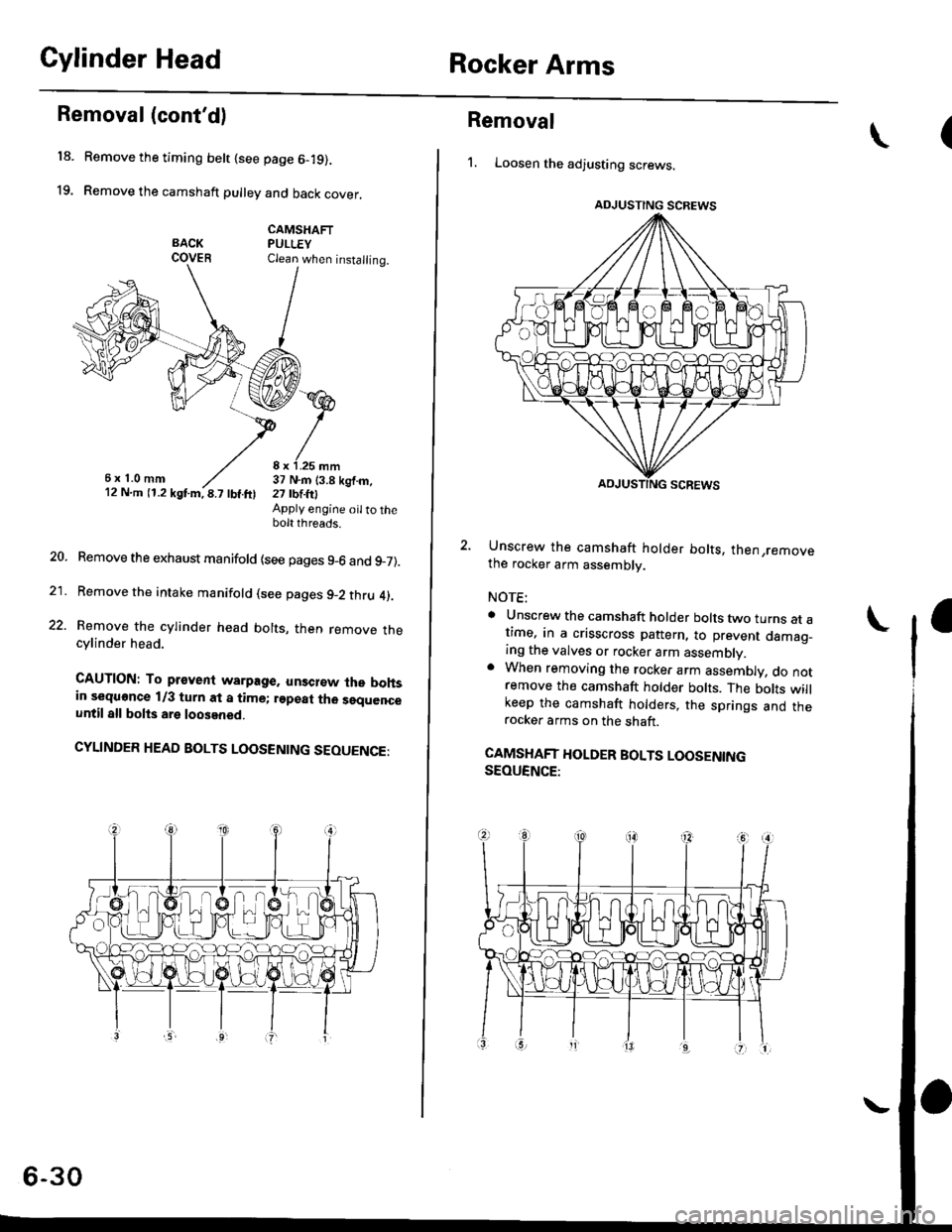
Remove the cylinder head bolts, then remove thecylinder head.
CAUTION: To pr€vent warpage, unsclew lhe bohsin sequonce 1/3 turn at a time; rgpeat tho sequenceuntil all bolts are loosened.
CYLINDER HEAD BOLTS LOOSENING SEOUENGE:
6-30
Removal
1. Loosen the adjusting screws.
2. Unscrew the camshaft holder bolts, then,removethe rocker arm assembly.
NOTE:
a Unscrew the camshaft holder bolts two turns at at,me, in a crisscross pattern, to prevent damao_ing the valves or rocker arm assembly.. When removing the rocker arm assembly, do notremove the camshaft holder bolts. The bolts willkeep the camshaft holders, the springs and therocker arms on the shaft.
CAMSHAFT HOLDER BOLTS LOOSENINGSEOUENCE:
\(
ADJUSTING SCREWS
Page 567 of 2189
J
Transaxle
cf utch .""""" 12'1
Manual Transmission ............"'.'..".'...'. 13-1
Automatic Transmission ........ "........ " ". 1 4-1
Differential ... 15-1
Driveshafts ." 16-1
Page 1043 of 2189
Driveshafts
Reassembly (cont'dl
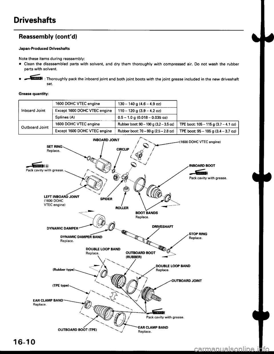
Japan-Produced Driveshafts
Note these items during reassembly.
. Clean the disassembled pans with solvent, and dry them thoroughly with compressed air. Do not wash the rubber
parts with solvent.
o r@l : Thoroughly pack the inboard joint and both joint boots with the joint grease included in the new driveshaft
set.
Grease quantity:
Inboard Joint
1600 DOHC WEC engine130 - 140 9 (4.6 - 4.9 oz)
Except 1600 DOHC VTEC engine110 - 120 g (3.9 - 4.2 oz)
Splines (Al0.5 - 1.0 g (0.018 - 0.035 oz)
Outboard Joint
'1600 DOHC WEC engineRubber boot 90 - 'l 00 g (3.2 - 3.5 oz)TPE boot; 105 - 115 9 (3.7 - 4.1 oz)
Except 1600 DOHC VTEC engineRubber boot 70 - 80 g |'2.5 - 2.8 ozlTPE boot 95 - 105 g (3.4 - 3.7 oz)
{1600 DOHC VTEC angine)
SET RINGReplace.
-6{@INBOARD BOOT
-6;Pack cavity with grease.
Pack cavity with grease.
DYNAMIC DAMPER
DYNAMICReplace.
DOUA|.I Lq)P BANDReplace.
(Rubber typc)LOOP BANDReplace.
Pack cavity with grease-
CLAMP BAND
],*"u, ,"^S
/ t'.t$ ,''
,/s
-'-
OUTBOARD BOOTIRUEBER)
16-10
tttt t*' -----_.r...-
._
Replace.
Page 1044 of 2189
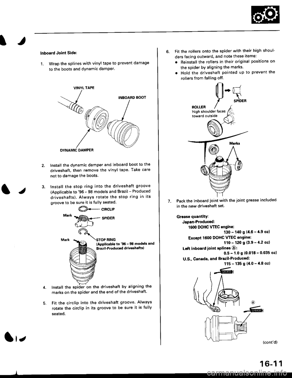
lnboard Joint Side:
1, Wrap the splines with vinyl tape to prevent damage
to the boots and dynamic damPer.
TAPE
INBOARD BOOT
DYNAMIC DAMPER
Install the dynamic damper and inboard boot to the
driveshaft, then remove the vinyl tape. Take care
not to damage the boots.
Install the stop ring into the driveshaft groove
(Applicsble to '96 - 98 models and Brazil - Produced
driveshafts). Always rotate the stop ring in its
groove to be sure it is fully seated.
@--c't"t't
STOP RING(ApplicablG to'96- 98 modob and
Brrzil-Producrd drivoshaftrl
Install the spiiler on the driveshaft by aligning the
marks on the sDider and the end of the driveshaft.
Fit the circlip into the driveshaft groove. Always
rotate the circlip in its groove to be sure it is fully
seated.
VINYL
- -
/
-<@
lr;
6. Fit the rollers onto the spider with their high shoul-
ders facing outward, and note these items:
. Reinstall the rollers in their original positions on
the spider by aligning the marks
. Hold the driveshaft pointed up to prevent the
rollers from falling off.
Pack the inboard joint with the joint grease included
in the new driveshaft set.
Grease quantity:
Japan-Produced:
1600 DOHC VTEC ongine:
130 - 1/t0 g 14.6 - '[.9 oz)
Except 1600 DOHC VTEC angine:
110 - 120 I {3'9 - il'2 oz}
Left inboard ioint splines O:
0'5 - 1.0 s (0.018 - 0'035 oz)
U.S,, Canada, and Brazil'Produced:
115 - 135 g (40-4.8ozl
7.
6
-6.l
(cont'd)
16-1 1
High shoulder faces
Page 1045 of 2189
Driveshafts
Reassembly (cont'dl
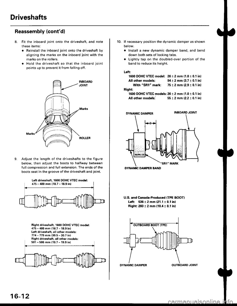
8. Fit the inboard joint onto the driveshaft, and note
these items:
. Reinstall the inboard joint onto the driveshaft by
aligning the marks on the inboard joint with the
marks on the rollers.
. Hold the driveshaft so that the inboard joint
points up to prevent it from falling off.
Adjust the length of the driveshafts to the figure
below, then adjust the boots to halfway between
full comDression and full extension. The ends of the
boots seat in the groove of the driveshaft and joint.
Right driveshaft, 1600 OOHC VTEC model:475 - 480 mm (18.7 - 18.9 in)Left driveshaft, all othei models:774-779 mm (30.5 - 30.7 in)Right driveshaft, all other models:501 - 506 mm 119.7 -'19.9 inl
Left driveshaft. 1600 DOHC WEC model:475 - 480 mm 118.7 - 18,9 inl
16-12
OYNAMIC DAMPEROUTBOARD JOINT
10. lf necessary position the dynamic damper as shown
Detow.
. Install a new dynamic damper band. and bend
down both sets of locking tabs.
. Lightly tap on the doubled-over ponjon of the
band to reduce its height.
Loft:
1600 DOHC VTEC model: 26 i 2 mm (1.0 t 0.1 inl
All other models: 9,1t 2 mm (3.7 10.1 inl
With "SR1" mark: 7512 mm 12.9 ! 0.1 inl
Right:
16dl DOHC VTEC models: 2612 mm 11.0 t 0.1 inl
All other modelii
DYNAMIC DAMPER
-SR1" MARK
U.S. and Canada-Produced ITPE BOOTI
Left 53612 mm {21.1 10.1 in}
Right: 2txt 12 mm {10.it 1 0.1 in}
5512 mm (2.2 t 0.1 inl
INBOARO JOINT
DYNAMIC DAMPER BAND